

Luxon Video TAB2VIRWD User Manual
1080P Turret &Bullet Camera
User Ma nual
Reg ula tor y Informa n
FCC I nforma n
FCC c omplian ce: Thi s equipment h as been
test ed and fo und to com ply wit h the lim its for a
dig ital dev ice, pu rsuan t to part 1 5 of the FCC
Rul es. The se limi ts are des igned t o provi de
reasonab le prot
n agai nst har mful
int erfere nce when t he equi pment i s operat ed in
a com mercia l envir onment . This eq uipme nt
gen erates , uses, a nd can rad iate rad io
fre quenc y energy a nd, if no t install ed and us ed
in ac cordan ce with t he ins
n manual , may
cau se harm ful inte rferen ce to radi o
com munic a
. Ope ra n of th is equipme nt in
a resid en
l are a is likel y to caus e harmfu l
int erferen ce in whi ch case t he user w ill b
e
req uired to c orrect t he inte rferen ce at his o wn
expense .
FCC
s
Thi s device co mplies w ith par t 15 of the F CC
Rul es. Ope ra
on is s ubjec t to the fol lowin g two
c
:
1. Th is devi ce may not c ause ha rmful
int erferen ce.
2. Th is devi ce must ac cept an y interf erence
rec eived, i nclud ing int erfere nce tha t may
cau se undesir ed opera
n.
EU Co nfo rmi ty St atement
upo n th e purchas e of eq uiv ale nt n ew eq uip ment,
or di sp ose o f it at d esi gn ate d col lec tio n point s.
For m ore i nf orm ati on se e:
www. recycl ethis .info.
2006/6 6/EC (b a
ery d ire ve):
Thi s product c ontain s a ba
ery t hat
canno t be disposed of a s unsorted
munic ipal wa ste in the E urope an
Union .
See t he produc t docum enta
n for sp ecific
ba
ery i nforma on. T he ba ery is m arked wi th
thi s symbo l, which m ay incl ude le
eri ng to
ind icate ca dmium (Cd ), lead ( Pb), or m ercur y (Hg).
2012/1 9/EU (W EEE dir e
ve) :
Produ cts mar ked with t his symb ol
canno t be disposed of a s unsorted
munic ip al wa ste i n the E urope an
Uni on . For p rop er re cyc lin g, r etu rn
thi s pr odu ct to y our l oca l su pplier
Thi s product a nd - if applic able - th e
sup plied a ccessor ies too a re marked
wit h "CE" an d compl y theref ore with
the app licab le harm onized E urope an
standa rds lis ted und e
r the L ow Volta ge Direc
ve
2006/9 5/EC, th e EMC Dir
ve 2004/ 108/EC ,
the Ro HS Di re
ve 2011/ 65/EU.
1.2 Overview
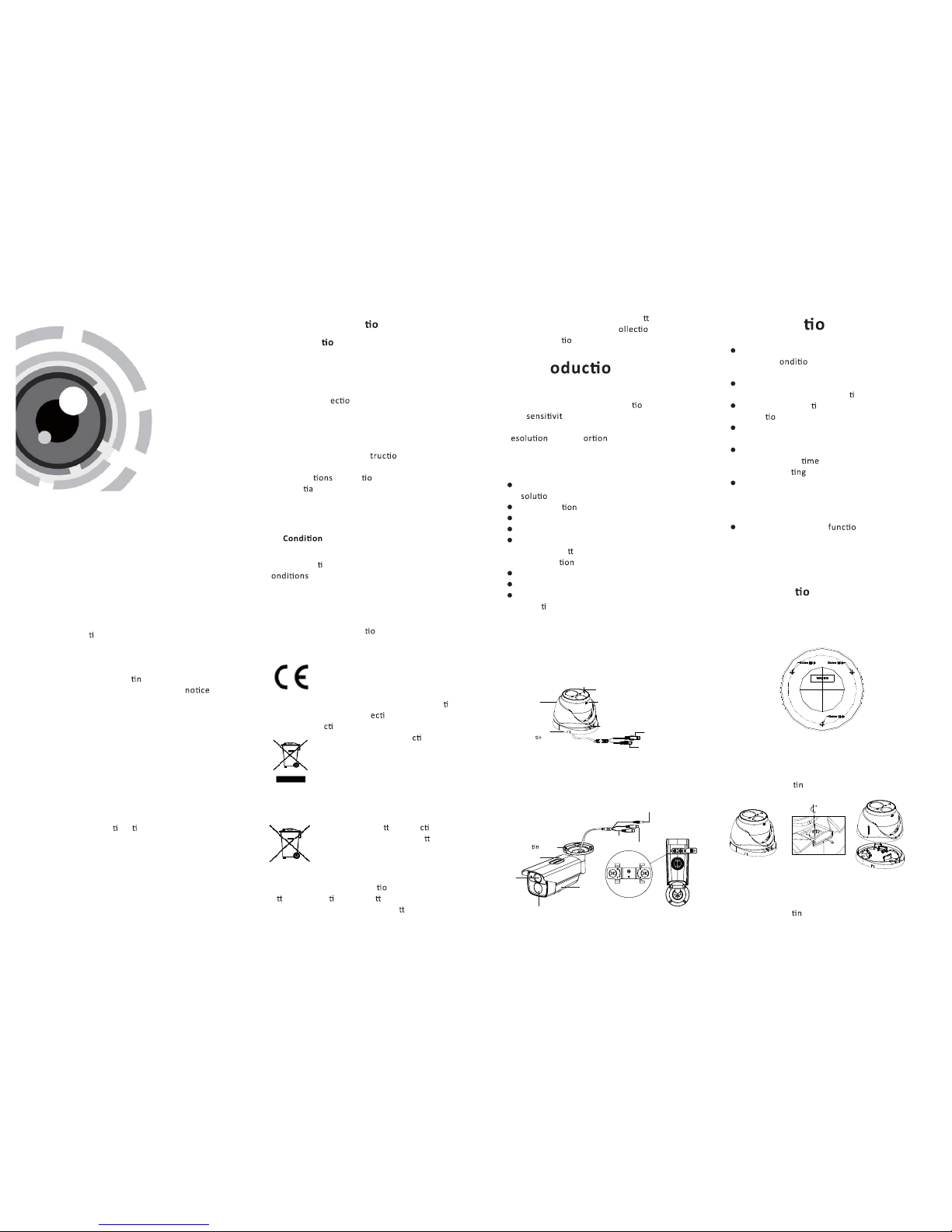
1.2 .1 Over view of Ty pe I Came ra
1.2 .2 Over view of Ty pe Came ra
II
HD Vide o Cable
Enclo sure
Zoom & Fo cus
Lock ScrewLock
Moun
g Base
Camer a
Power C able
Power C able
IR LED
Lens
Main B ody
Sun Sh ield
Moun
g Base
HD Video Cab le
CVBS Cab le
Zoom
Focu s
1 Intr n
1.1 Product Features
Thi s camera adop ts new ge nera n s ensor w ith
hig h
y and a dvanc ed circu it boar d desig n
tec hnology. It posses ses t he featu res of hi gh
r
, low d ist , and l ow noise, et c. It is
ext remely s uitab le for supe rvisory s ystem an d
ima ge processi ng syste m.
The m ain feat ures are a s follo ws:
Hig h perfor mance C MOS sen sor and h igh
re
n bri ng high-qu ality i mage;
Low illu mina ;
Sup port IR c ut filte r with aut o switc h;
OSD m enu, pa ramete rs are con figurab le;
Support a uto whi te bala nce, au to gain co ntrol,
ele ctron ic shu
er co ntrol an d inter nal
syn chroni za
;
SMA RT IR mod e;
Uni t transm ission con trol;
Adv anced 3 -axis de sign me ets diff erent
ins talla
on re quirem ents.
Ple ase make s ure tha t the devi ce in the p ackag e
is in g ood c
n and a ll the as sembl y parts
are i nclud ed.
Make s ure tha t all the re lated e quipm ent is
pow er-off d uring t he insta lla
on.
Che ck the sp ecific a o n of the pr oducts for t he
ins talla
n env ironme nt.
Che ck whet her the p ower sup ply is ma tched
wit h your po wer outp ut to avoi d damag e.
Ple ase make s ure the wa ll is str ong eno ugh to
wit hstand t hree
s the w eight of t he came ra
and t he moun
.
If th e wall is t he ceme nt wall, y ou need to i nsert
exp ansio n screws b efore yo u instal l the cam era.
If th e wall is t he wooden wa ll, you c an use
sel f-tap ping sc rew to sec ure the ca mera.
If th e product d oes not n prope rly,
ple ase con tact you r deale r or the ne arest
ser vice ce nter. Do not d isassem ble the c amera
for re pair or m ainte nance by you rself.
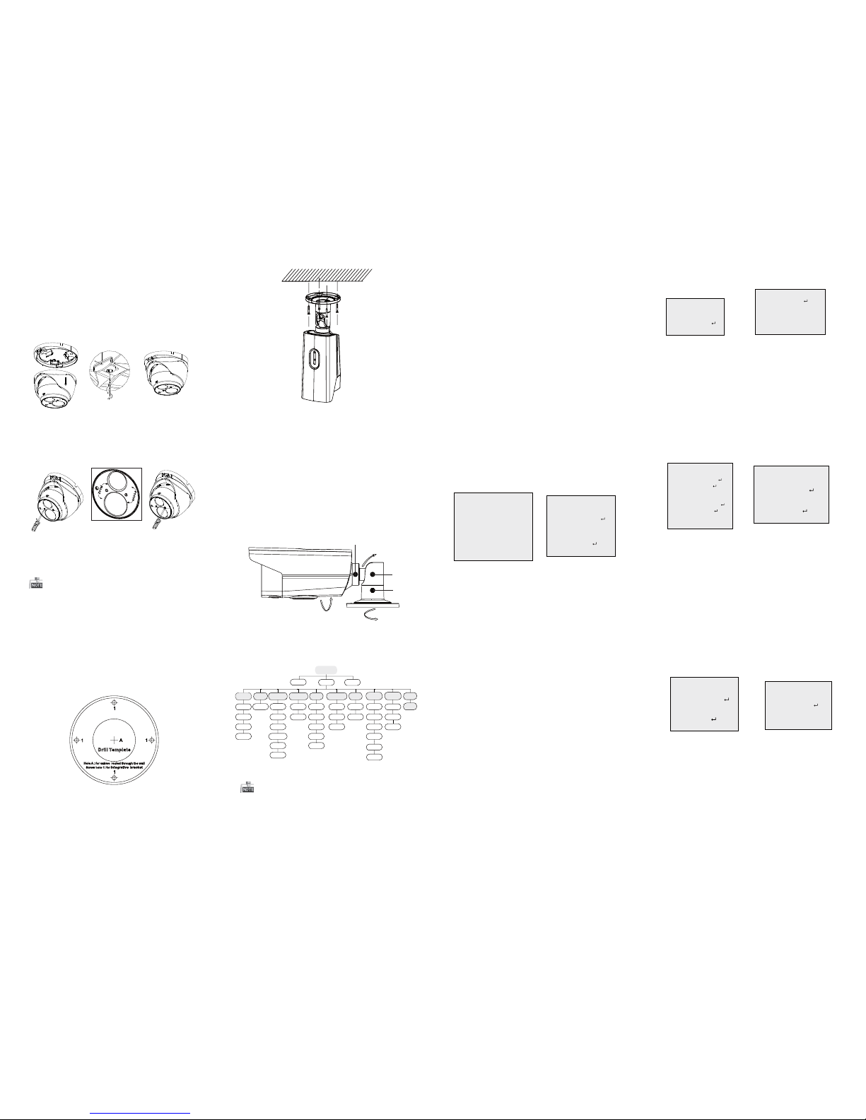
2.1 Installa n of Type CameraI
Ste ps:
1.Dr ill the s crew hol es and th e cable h ole on th e
cei ling ac cordin g to the su pplie d drill t emplat e.
Fig ure 2-1 T he Dril l Temp late
2 to di sassemb le the ca mera
.
fro m the mou n g base.
3.Fi x the mou n
g bas e to the ce iling .
Fig ure 2-2 Re lease T he Lock S crew
For p roper re cycli ng, retu rn the ba
ery t o your
supplie r or to a des ignate d c
n poi nt. For
mor e inform a
n see : www.rec yclet his.in fo.
2 Installa n
Bef ore yo u star t:
Thank y ou for pur chasing ou r product . If there
are a ny ques
ons , or requ ests, pl ease do n ot
hes itate to c ontact t he deal er.
Thi s manual ma y contai n severa l techn ical
inc orrect pla ces or p rin
g err ors, and t he
con tent is subje ct to cha nge wit hout
.
The u pdates w ill be ad ded to th e new vers ion of
thi s manual. We wi ll read ily imp rove or up date
the p roducts o r proced ures desc ribed i n the
manua l.
DISCLA IMER STATEMENT
Underwr iters La borato ries In c. (”UL” has n ot)
test ed the pe rforman ce or reli ability o f the
sec urity o r signa ling aspe cts of th is produc t.
UL ha s only te ste
d for fir e, shoc k or casual ty
haz ards as ou tline d in Ul’s St andard(s ) for Safe ty,
UL60950 -1. UL Ce r
fica on doe s not cov er the
per forman ce or rel iabilit y of the se curit y or
sig nalin g aspec ts of thi s product . UL MAKES N O
REP RESEN TATIO NS, WARRANT IES OR
CER TIFIC ATIO NS WHATSOEV ER REGARDI NG
THE P ERFORMA NCE OR RE LIABILIT Y OF ANY
SEC URITY OR SIGN ALING R ELATED FU NCTIONS
OF TH IS PROD UCT.
Fig ure 1-1 O vervie w of Type I Ca mera
Fig ure 1-2 O vervie w of Type C ameraII
HD-TVI
Release the lock screw
3 Menu Operaon
Figure 3-1 Main Menu
Menu
SCENE
LENS
RESET
EXPOSURE
WB
DAY&NIGHT
BACKLIGHT
NR
SPECIAL
ADJUST
INDOOR
OUTDOOR
INDOOR1
LOWLIGHT
MANUAL
SHUTTER
AGC
SENS-UP
BRIGHTNESS
D-WDR
DEFOG
BLC
HSBLC
ATW
AWC-SET
INDOOR
OUTDOOR
MANUAL
COLOR
B/W
EXT
2DN R
3DN R
CAM
TITLE
D-EFFECT
MOTION
PRIVACY
LAUGUAGE
DEFECT
VERSION
SHARPNESS
MONITOR
LSC
VIDEO.
OUT
EXIT
SETUP
3.1 VIDEO.OUT
PAL or NTSC is select able .
3.2 LANGUAGE
English, Japanes e, CHN1 , CHN2, Ko rean, German,
Fre nch, Itali an, Spanish, P olish, etc., a re selectable.
3.3SETUP
3.3.1 SCEN E
You can select i ndoor, outdoor, in door 1 and low
-light a s the working envir onments.
3.3.2 LENS
The camera i s equipped wi th a fixed lens.
3.3.3 EXPOSURE
EXPOSURE
1. SHUTTER AUTO
2. AGC OFF
3. SENS-UP ---
4. BRIGHTNESS ---|------ 40
5. DEFOG OFF
6. BACKLIGHT OFF
7. RETURN RET
Figure 3-2 Exposure
SHUTTER: A UTO,1/25, 1/50, F LK, 1/200, 1/400,
1/1k, 1/2k, 1/5k, 1/10k, 1/50k are sel ectable.
: You can s et the AGC val ue from 0 t o 15.AGC
: You can s et the SENS-U P to OFF or AU TO.SENS-UP
: You can s et the brightness va lueBRIGHTNES S
fro m 1 to 100.
: You can s et the defog f uncon as ON t oDEFOG
enable the funcon. Posion, size, and the d efog
gradaon a re configurable.
3.3.4 Back light
Backlight Compensaon (BLC ):
Set the ga in of BLC a s High, Middle, or Lo w.-GAIN:
Press the up/down/le/righ t buon to-AREA:
define the B LC posion and size. Select RET
or
AGAIN t o go back the BLC m enu or re -define the
BLC a rea.
Rest ore the B LC seng s to the default .-Default:
HSBLC: Select a n HSBLC area. Set the DISPLAY
status a s ON. Press the up/down/le/right buo n
to de fine the ar ea posion and s ize. Set the HSB LC
LEVEL fro m 0 to 100. Select ALL DAY or Night for the
HSB LC mode. Set the B LACK MASK status as O N or
OFF.
HSBLC
1. SELECT AREA 1
2. DISPLAY ON
3. LEVEL ---|------ 40
4. MODE ALL DAY
5. BLACK MASK ON
6. DEFAULT
7. RETURN RET
Figure 3 -3 HSBLC
3.3.5 White Balance (WB)
INDOOR, OUTDOOR, MANUAL , ATW (Auto-tr acking
White Balan ce), AWC→SET a re selectable.
3.3.6 Day & Nig ht
Color, B/W, and EXT are selectable for DAY and
NIGHT switches.
3.3.7 NR
: You can s et 2D NR sta tus as ON or OF F.2D NR
: Set the Smart N R status as ON and adjus t3D NR
the 3D smart N R sensivity rang es from 0 to 100.
Set the 3 D NR LEVEL ranges fr om 0 to 100. Set the
2D&3D NR
1. 2DNR OFF
2. 3DNR ON
3. RETUR N RET
3D NR
1. SMART NR ON
2. LEVEL ------|--8 0
3. START. AGC -|--------10
4. END. AGC -|--------10
5. RETURN RET
Figure 3 -5 NR
Figure 3 -6 3D NR
3.3.8 SPECIAL
Edi t the camera tl e on this sec on.Camera Title:
D-e ffect:
Set the f reeze func on as ON o r OFF.-FREEZE:
OFF, MIRROR, V-F LIP, and R OTATE ar e-MIRROR:
selectable fo r mirror.
Define the zoom a rea by co nfiguring-D-Z OOM:
the posi on fro m PAN & TILT.
The D-Zoom area, sensivity-SMART D-ZOOM:
and me are co nfigurable.
Set the N EG IMAGE a s ON or OFF.-NEG.IMAGE:
SPECIAL
1. CAM TITLE ON
2. D-DFFECT
3. MOTION OFF
4. PRIVACY OFF
5. LANGUAGE ENG
6. DEFECT
7. VERSION 130722
8. RETURN RET
Figur e 3-7 Speci al
MOTION
1. SELECT AREA1
2. DISPLAY ON
3. SENSITIVITY ----|---- 30
4. MOTION VIEW ON
5. DEFAULT
6. RETURN RET
Figure 3 -8 Moo n Detec on
Moon : Select a MOTION ar ea. Set the D ISPLAY
status a s ON or OFF. Press th e up/down/le/right
buon t o define th e posion and s ize of the are a.
Set the S ENSITIVITY from 0 to 60. S et the MOTION
VIEW status as O N or OFF.
Privacy: Select a P RIVACY ar ea. Set the DISP LAY
status a s INV, MOSA IC, COLO R or OFF. Pre ss the
up/down/le/right buo n to define the posion
and size o f the area.
Defe ct: LIVE DP C, STATIC DPC and Bl ack DPC are
adjustable in this secon.
: You can che ck the sow are vers ion of theVe rsion
device.
PRIVACY
1. SELECT AREA 1
2. DISPLAY MOSAIC
3. COLOR 10
4. TRANS. 1
5. DEFAULT
6. RETURN RET
ADJUST
1. SHARPNESS
--------|15
2. MONITOR LCD
3. LSC OFF
4. VIDEO. OUT PAL
5. RETURN RET
3.3.9 ADJUST
: Adjust the sharpness fro m 0 to 15.Sharpness
: Monitor C RT, and Monitor L CD areMonitor
selectable.
: Set the LSC s tatus as ON or O FF.LSC
3.3 .10 RESET
Res et all the s engs t o the default.
3.3.11 EXIT
Pre ss OK to exi t the menu.
START. AGC l evel as the t hreshold to enabl e AGC,
and set the E ND. AGC le vel as the th reshold to
disable AGC .
Figur e 3-9 Privacy Mask
Figur e 3-10 Adjust
Ste ps:
1.Drill th e screw holes and the cabl e hole in the
ceili ng according t o the supplied drill temp late.
2.Hammer t he supplied plasc expansion b olt into
the scr ew holes.
2.2 Installaon of Type II
Camera
Figur e 2-5 Drill Template
Figur e 2-6 Fix t he Camera to the Ceiling
Figure 2- 7 3-axis Adj ustme nt
5. Ad just th e surveilla nce angle.
1). Loosen No.1 adjusng screw t o adjust the pan
posion (0 ~ 360 ).° °
2).Tighte n No.1 adjusng screw.
3). Loosen No.2 adjusng screw t o adjust the
lng posion(0 ~ 90 ).° °
4).Tighte n No.2 adjusng screw.
5). Loosen No.3 adjusng screw t o adjust the
rota on posion 0 ~ 360 .( ° °)
6).Tighte n No.3 adjusng screw.
3.Route the c ables to the cable hole and connect
the corresponding cables.
4.Fi x the camera to the ceiling w ith the sup plied
screws .
A coa xial camera c ontrolle r (purc hase separately)
is re quired to select the menu and adjust the
camera par ameters.
4.Route the c ables to the cable hole and connect
the corresponding cables.
5.Secure the camer a to the mounng base by
ghtening the lock scr ew.
6.Adjus t the camera accord ing to the figur e below
to get a n opmum angle.
Figure 2 -3 3-axi s Adjustment
7.Use the screw driver to adjust the ZOOM scr ew
and the FOCUS s crew un l you ge t the opmum
image.
Figure 2-4 Zoom and Focus Adjus tment
Both wall mo unng and ceilin g moun ng are
suita ble for type bull et camera. Ceiling m ounn g
will be ta ken as an exampl e in the secon. An d you
can ta ke steps of ceiling mounng a s a reference
if wa ll mounng is adopted.
0~360
0~360
09~0
1
2
3
 Loading...