

Luxon Video NVR-16, NVR-16D1, NVR-32, NVR-32H User Manual

NVR series
NVR-16
NVR-16D1
NVR-32
NVR-32H
User Manual
July 2010
FCC NOTICE (Class A)
This device complies with Part 15 of the FCC Rules. Operation is subject to the following two conditions: (1)
this device may not cause harmful interference, and (2) this device must accept any interference received,
including interference that may cause undesired operation.
Federal Communications Commission Statement
NOTE- This equipment has been tested and found to comply with the limits for a Class A digital device, pursuant to
Part 15 of the FCC Rules. These limits are designed to provide reasonable protection against harmful interference
in a residential installation. This equipment generates uses and can radiate radio frequency energy and, if not
installed and used in accordance with the instructions, may cause harmful interference to radio communications.
However, there is no guarantee that interference will not occur in a particular installation. If this equipment does
cause harmful interference to radio or television reception, which can be determined by tuning the equipment off
and on, the user is encouraged to try to correct the interference by one or more of the following measures:
Reorient or relocate the receiving antenna.
Increase the separation between the equipment and receiver.
Connect the equipment into an outlet on a circuit different from that to which the receiver is connected.
Consult the dealer or an experienced radio/television technician for help.
Class A ITE
Class A ITE is a category of all other ITE which satisfies the class A ITE limits but not the class B ITE limits. Such
equipment should not be restricted in its sale but the following warning shall be included in the instructions for use:
Warning ─This is a class A product. In a domestic environment this product may cause radio interference in which
case the user may be required to take adequate measures.
European Community Compliance Statement (Class A)
This product is herewith confirmed to comply with the requirements set out in the Council Directives on
the Approximation of the laws of the Member States relating to Electromagnetic Compatibility Directive
2004/108/EC.
Warning - This is a Class A product. In a domestic environment this product may cause radio interference in which case
the user may be required to take adequate measures to correct this interference.
DISCLAIMER
No warranty or representation, either expressed or implied, is made with respect to the contents of this
documentation, its quality, performance, merchantability, or fitness for a particular purpose. Information presented
in this documentation has been carefully checked for reliability; however, no responsibility is assumed for
inaccuracies. The information contained in this documentation is subject to change without notice.
In no event will Luxon Video be liable for direct, indirect, special, incidental, or consequential damages arising out of
the use or inability to use this product or documentation, even if advised of the possibility of such damages.
TRADEMARKS
Luxon Video, being authorized Luxon Video Inc. to use, is registered trademarks of Luxon Video Inc. IBM PC is a
registered trademark of International Business Machines Corporation. Macintosh is a registered trademark of Apple
Computer, Inc. Microsoft is a registered trademark and Windows is a trademark of Microsoft Corporation. All other
products or corporate names mentioned in this documentation are for identification and explanation purposes only, and
may be trademarks or registered trademarks of their respective owners.
COPYRIGHT
© 2010 by Luxon Video Inc. All rights reserved. No part of this publication may be reproduced, transmitted,
transcribed, stored in a retrieval system, or translated into any language in any form by any means without the written
permission of Luxon Video Inc.
The mark of Crossed-out wheeled bin indicates that this product must not be disposed of with your other
household waste. Instead, you need to dispose of the waste equipment by handing it over to a designated
collection point for the recycling of waste electrical and electronic equipment. For more information about
where to drop off your waste equipment for recycling, please contact your household waste disposal
service or the shop where you purchased the product.
WARNING
- TO REDUCE RISK OF FIRE OR ELECTRIC SHOCK, DO NOT EXPOSE THIS APPLIANCE TO
RAIN OR MOISTURE.
- GUARANTEE BECOMES VOID IN CASE OF ANY UNAUTHORIZED MODIFICATIONS INTO DOM
CONTENTS.
- DO NOT REMOVE REMOVABLE HDD TRAY SHILE SYSTEM IN USE. IT WOULD DAMAGE DOM
CONTENTS.
- DVR SUPPORTS 1024 x 768 OR 1280 x 1024 DISPLAY RESOULTIONS. OTHER DISPLAY
RESOULTUIONS WOULD CASUE ABNORMAL DVR FUNCTIONS.
- DO NOT INSTALL DVR IN THE AIRTIGHT ENVIROEMENT. IT WOULD CAUSE INSTABILITY OF
THE SYSTEM.
CAUTION
IF THERE IS ANY DAMAGE, SHORTAGE OR INAPPROPRIATE ITEM IN THE PACKAGE, PLEASE
CONTACT WITH YOUR LOCAL DEALER. WARRANTY VOID FOR ANY UNAUTHORIZED PRODUCT
MODIFICATION.
Manual Conventions
The following conventions are used throughout this manual
Caution symbol is intended to alert the user of the important installation and operating instructions. Fail to
comply may damage the system.
i
Information symbol is intended to provide additional information for the purpose of clarification.

TABLE OF CONTENTS
Chapter 1 Introduction .................................................................................... 1
1.1 Package Contents .................................................................................................................... 1
1.2 Features ................................................................................................................................... 1
1.3 Hardware Introduction .............................................................................................................. 3
1.3.1 Front Panel of the NVR RACK ...................................................................................... 3
1.3.2 Back Panel of NVR Rack .............................................................................................. 3
(NOTE: Not all items are included on all models. IN/OUTPUT placement may vary slot to slot
between models!) ..................................................................................................................... 3
1.4 Connecting Devices ................................................................................................................. 4
1.5 Sensor/Relay device pinhole allocation ................................................................................... 4
1.6 Formatting Hard Disk ............................................................................................................... 5
Chapter 2 Using the DVR Software ................................................................ 7
2.1 Running the Unit for the First Time .......................................................................................... 7
2.2 Function buttons in Advanced/Preview Mode .......................................................................... 7
(13) iPOSLive Images ............................................................................................................. 11
2.2.1 Using Event Log Viewer .............................................................................................. 12
2.2.1.1 Using POSViewer ......................................................................................................... 13
2.2.1.2 Using Counting Log Viewer ......................................................................................... 14
2.2.1.3 Using the Object Viewer .............................................................................................. 15
2.3 Function Buttons in Playback Mode ....................................................................................... 16
2.3.1 To Cut and Save the Wanted Portion of the Recorded Video ...................................... 19
2.3.2 To Bookmark a Section of the Video ........................................................................... 20
2.3.3 To Search Using the Visual Search ............................................................................. 21
2.3.4 To Search Using the Event Search ............................................................................. 21
2.3.5 To Search Using the Intelligent Search ....................................................................... 22
2.3.6 Watermark Verification ................................................................................................ 22
2.4 Function Buttons in Compact Mode ................................................................ ....................... 23
2.5 Function Buttons in PTZ Camera Controller .......................................................................... 24
2.6 Setting Up and Using the EMAP ............................................................................................ 25
2.6.1 To Set Up the EMAP ................................................................................................... 25
2.6.2 To Use the EMAP ........................................................................................................ 26
2.7 To Setup the PTZ/IP PTZ Camera ......................................................................................... 27
2.7.1 Setup the PTZ Camera ............................................................................................... 27
2.7.2 Setup the IP PTZ Camera ........................................................................................... 29
Chapter 3 Customizing the DVR System ..................................................... 31
3.1 System Setting ....................................................................................................................... 31
3.1.1 To Set the POS Setting ............................................................................................... 44
3.1.1.1 General Setting.............................................................................................................. 44
3.1.1.2 Advanced Setting .......................................................................................................... 49
3.1.1.3 POS Database Setting ................................................................................................. 49
3.1.2 UPS Connection .......................................................................................................... 50
3.2 Camera Setting ...................................................................................................................... 52

3.2.1 Setup the Object Counting .......................................................................................... 58
3.2.2 To Setup the FaceFinder ................................................................ ............................. 60
3.2.3 Setup PTZ Tracking..................................................................................................... 62
3.2.4 Create a Camera Group .............................................................................................. 64
3.3 Recording Setting .................................................................................................................. 66
3.3.1 To Mask/Shield an area on the screen ........................................................................ 71
3.3.2 To show and change the color of the Mask ................................................................. 71
3.3.3 To Playback Encrypted Video ...................................................................................... 71
3.4 Network Setting ...................................................................................................................... 72
3.5 Schedule Setting .................................................................................................................... 75
3.5.1 Set schedule at specific portion of time ....................................................................... 76
3.6 Backup Setting ....................................................................................................................... 77
3.6.1 To Backup file .............................................................................................................. 77
3.6.2 Setup Quick Backup .................................................................................................... 78
3.7 Sensor Setting ....................................................................................................................... 79
3.7.1 To Setup External I/O Box ........................................................................................... 80
3.8 Relay Setting ................................................................ ................................ .......................... 81
3.9 Alarm Setting ......................................................................................................................... 82
3.9.1 To Setup Alarm Relay: ................................................................................................. 88
3.9.2 To Setup the Alarm Sound Setting: ............................................................................. 88
3.9.3 To Setup Call Out List: ................................................................................................. 89
3.9.4 To Setup Send E-mail Setting: .................................................................................... 90
3.9.5 To Setup FTP Setting: ................................................................................................. 91
3.9.6 To Setup Alarm Recording Setting: ............................................................................. 91
3.9.7 To Setup SMS/MMS Setting: ....................................................................................... 92
3.9.8 To Setup PTZ Preset Point: ......................................................................................... 93
3.9.9 To Setup Alarm SOP: .................................................................................................. 93
3.9.10 To Setup CMS Setting ................................................................................................. 93
3.9.11 To Setup POS Keyword Setting .................................................................................. 94
3.9.12 Missing, Suspicious Object, and Scene Change Detected .......................................... 95
3.10 User Setting ........................................................................................................................... 97
Chapter 4 Backup Video Players .................................................................. 99
4.1 Familiarizing QPlayer Buttons ................................................................................................ 99
4.1.1 Watermark Verification .............................................................................................. 101
Chapter 5 Using Functional Keys ............................................................... 102
Chapter 6 Using the Remote Programs ..................................................... 103
6.1 Familiarizing the WebViewer Buttons ................................................................................... 104
6.1.1 To Setup Remote System Setting ............................................................................. 106
6.1.1.1 Basic Setting ................................................................................................................ 106
6.1.1.2 Advance Setting .......................................................................................................... 108
6.2 Familiarizing the WebViewer PTZ Buttons ........................................................................... 122
6.3 Familiarizing the Remote Console Buttons .......................................................................... 123
6.3.1 To Setup Remote Console Setting ............................................................................ 124
6.3.2 Familiarizing the Buttons in PTZ Camera Controller ................................................. 125

6.4 Using the Remote Playback ................................................................................................. 126
6.4.1 Familiarizing the Local Playback Buttons .................................................................. 127
6.4.2 Familiarizing the RealTime Playback Buttons ........................................................... 129
6.4.3 Familiarizing the Download and Playback Buttons .................................................... 131
6.5 Using HandyViewer to Access DVR server .......................................................................... 133
6.6 Using PDAViewer to Access DVR Server ............................................................................ 133
6.6.1 To install PDAViewer from the Internet ...................................................................... 133
6.6.2 To Use the PDAViewer .............................................................................................. 134
6.6.3 To Playback in PDAViewer ........................................................................................ 135
6.6.4 Using JavaViewer to Access DVR Server ................................................................. 136
6.6.5 To Use the JAVA-Viewer ............................................................................................ 137
Chapter 7 Image Verification ...................................................................... 138
7.1 To Run the ImageVerification program ................................................................................. 138
Chapter 8 iEnhance ..................................................................................... 139
8.1 To Use iStable ................................ ................................ ................................ ...................... 140
Chapter 9 Web Tools ................................................................................... 142
9.1 Dispatch Server ................................................................................................................... 142
9.2 Remote Setup ...................................................................................................................... 143
9.2.1 To Add DVR server .................................................................................................... 143
9.2.2 To Setup Remote DVR Server .................................................................................. 144
9.2.2.1 System Setting ............................................................................................................ 144
9.2.2.2 Camera Setting............................................................................................................ 147
9.2.2.3 Record Setting ............................................................................................................. 148
9.2.2.4 Network Setting ........................................................................................................... 149
9.2.2.5 Schedule Setting ......................................................................................................... 152
9.2.2.6 Alarm Setting ............................................................................................................... 153
9.3 Remote Backup ................................................................................................................... 158
Chapter 10 Using the Remote Control Server ............................................. 160
Appendix A Network Service Port ............................................................... 161
Appendix B Install Extra Hard Disk (RACK series) ..................................... 162
1
Chapter 1 Introduction
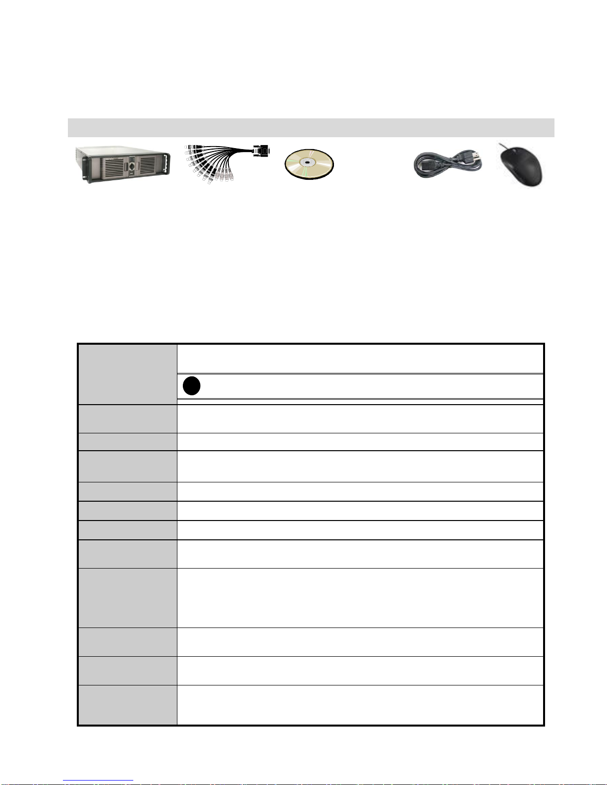
1.1 Package Contents
Recorder Package
(1)
(2)
(3)
(4)
(5)
(1) Recorder RACK unit
(2) 2 x AV cable
(3) Utility Software CD (Manual included)
(4) Power Cord
(5) USB optical mouse
1.2 Features
Recording Modes
Continuous Recording / Smart Recording / Motion Recording / Audio Recording /
Alarm Recording / Manual Recording
i
All modes can be triggered by schedule
De-interlace
Options
Optimize for dynamic or static camera scenes
Motion Detection
Detecting any kind of movements within the camera focus
Privacy Protection
Editable shield preventing private areas from monitoring and recording
EMAP Function
Show the positions of cameras, sensors, relays and triggered status
Attention Please
Enable dialogs to trace if operator pays attention to security monitor
Powerful Search
By date, time, camera, area, event, vision, and log file
Bookmark
Easily save links to particular locations of recorded data and play them directly from
the saved links
POS Integration
Compatible with most commonly used POS system
Easy to add POS protocol
Confidential Word Filter
Change location of POS text on camera display image
Advanced Event
Log Viewer
Details complete event logs according to your selection on event, operation, POS,
system and network events.
Alarm Triggered
Mode
Single event or multiple events as alarm trigger conditions
Smart Alert
Functions
Launch EMAP / Cam display / Warning sound / Email / Make a phone call / Send files
to FTP / SMS and MMS / PTZ preset point tracking / Alarm SOP wizard / Start
recording / Enlarge camera view

2
Remote Access
Webcam via regular IE browser
Remote Console
NVR-CMS Central Management System
Web Cam / Remote
Manager
Multiple DVR and IP cameras on your IE browser
Record 16 cameras on remote side
Dispatch Server
Share transmission loading; enable more clients at remote access & high-speed data
transmission.
PDAViewer
4-cam view, full screen and live audio
DDNS
Allow remote clients to search dynamic servers without enquiring for server’s IP
address
iStable
Fix shaking and jolts impact on video with just one click
iEnhance
Enhance video quality such as Brightness, Contrast, Hue, Saturation, Sharpness,
Noise Reduction, De-interlace and Gray Scale of recorded data
3
1.3 Hardware Introduction
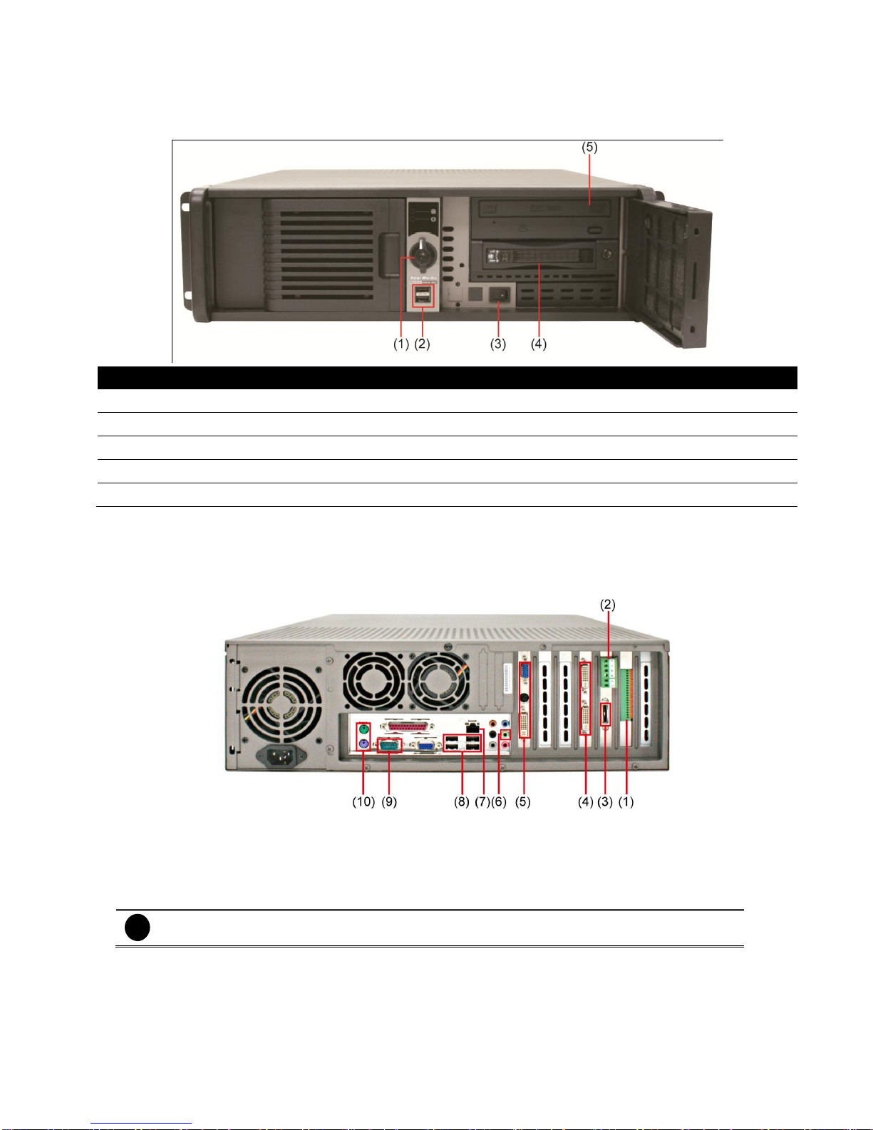
1.3.1 Front Panel of the NVR RACK
Name
Function
(1) Locker
To lock the front cover
(2) USB port x 2
To connect external USB devices
(3) Power switch
To on/off the system unit
(4) Removable HDD drawer
It can be installed the SATA hard disk
(5) DVD-RW
To backup recorded file on DVD-R/RW disk
1.3.2 Back Panel of NVR Rack
(NOTE: Not all items are included on all models. IN/OUTPUT placement may vary slot to slot between models!)
(1)
Sensor and Relay connection interface
(2)
RS485 interface
(3)
eSATA interface
(4)
AV Input
(5)
VGA Output
(6)
Audio output
(7)
Ethernet port
(8)
USB port x 4
(9)
COM port
(10)
Mouse & Keyboard Input
i
RS-485 interface doesn’t support to connect with RS-485 interface of E-I/O box device directly.
4
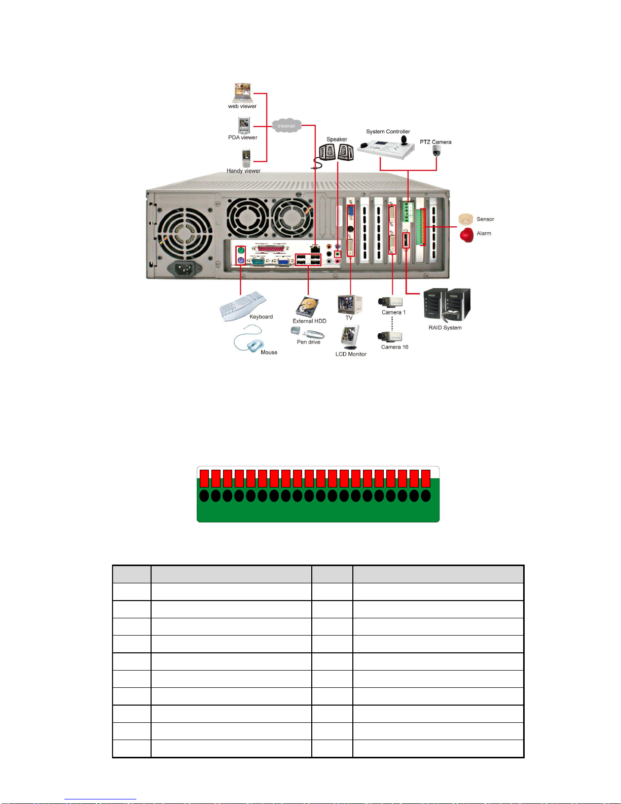
1.4 Connecting Devices
1.5 Sensor/Relay device pinhole allocation
The I/O card enables you to connect (4) sensor inputs and (4) relay outputs. Just connect the external
sensor and relay pin directly to the I/O card pinhole. Check the table below and locate which pinhole is
assigned to sensor input and relay output.
2019181716151413121110987654321
The signal from the sensor (i.e., infrared sensors, smoke detectors, proximity sensors, door sensors, etc.) is
being transmitted to the I/O card and this triggers the system to respond and send signal to relay device (i.e.,
alarm, telephone etc).
Pin #
Definition
Pin #
Definition
1
Sensor input signal 1+
11
Relay Normal Close 1
2
Sensor output signal 1-(GND)
12
Relay Common 2
3
Sensor input signal 2+
13
Relay Normal Open 2
4
Sensor output signal 2-(GND)
14
Relay Normal Close 2
5
Sensor input signal 3+
15
Relay Common 3
6
Sensor output signal 3-(GND)
16
Relay Normal Open 3
7
Sensor input signal 4+
17
Relay Normal Close 3
8
Sensor output signal 4-(GND)
18
Relay Common 4
9
Relay Common 1
19
Relay Normal Open 4
10
Relay Normal Open 1
20
Relay Normal Close 4

5
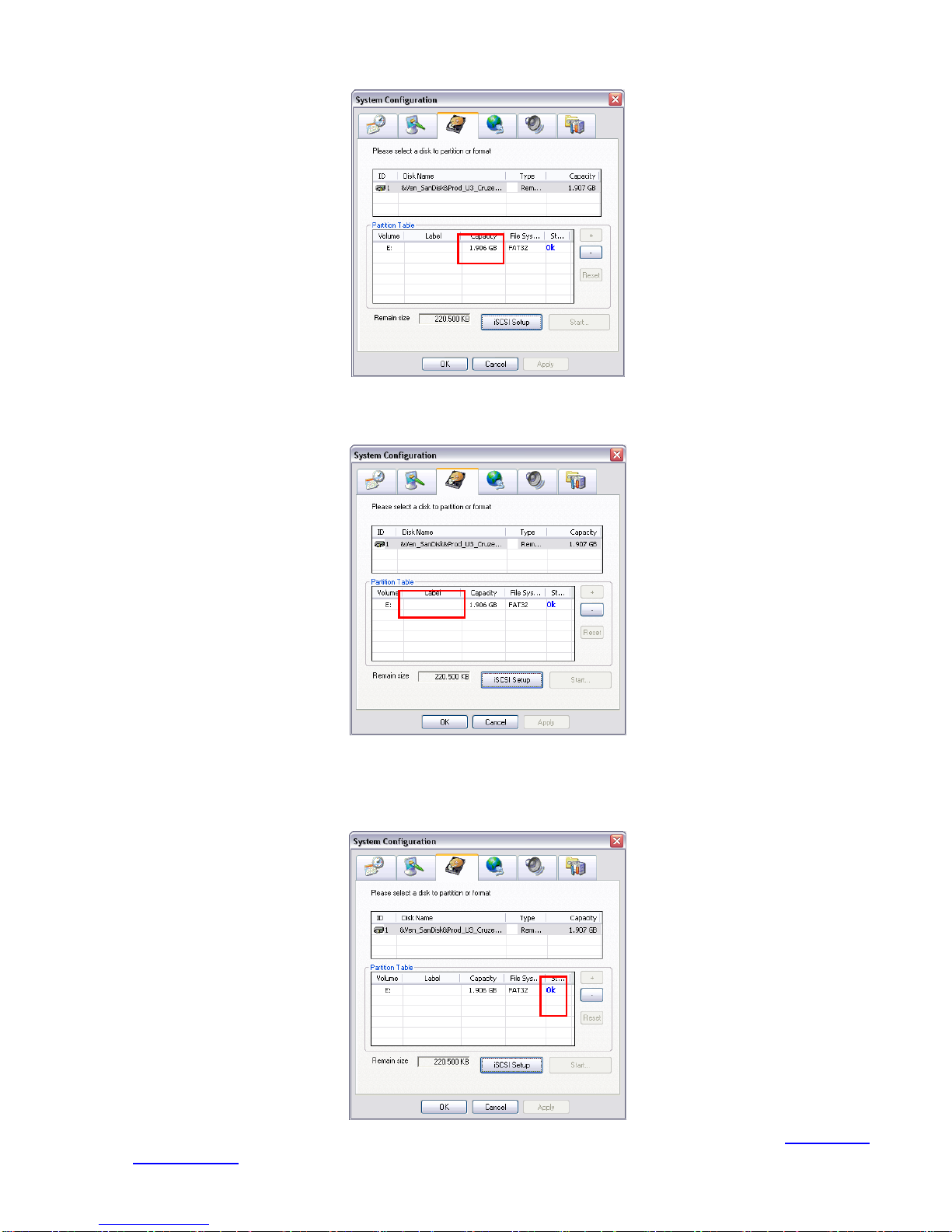
1.6 Formatting Hard Disk
User can format un-formatted hard disk by Disk management function. The hard disk must format in order
to record the video data. Follow the below steps to format and partition the hard disk.
i
- Stop recording before formatting or partitioning hard disk.
- The 1st install hard disk is not able to re-format and partition unless it is un-format when install into DVR
server.
- The hard disk has been added into storage path or formatted that is not able to re-format and partition.
- Do Not save any recording data on DOM.
1. Turn on the power of DVR server after hard disk has installed.
2. Click Setup and enter ID and password for authentication.
3. Click System → System Configuration and click Setting.
4. Select Disk Management tab.
5. User should see the installed hard disk is listed. Click on the hard disk that wants to format or partition.
6
6. Click + button to add the selected hard disk into Partition Table section.
7. User can adjust the capacity of partition by clicking Capacity column and enter the capacity. If user
doesn’t want to divide hard disk into several partitions, and then, just leave the capacity without change.
8. The partition can be named by clicking on Label column and enter the name.
9. To create more than one partition, do the steps 7 and 8 again.
10. When all the partition has been added, click Start to format all partitions.
11. When the formatting complete, the each partition status will change to OK.
12. Click OK to exit when formatting is completed.
13. Now, user can assign formatted hard disk or partition as a storage path (see also Chapter 4.1
System setting).
7
Chapter 2 Using the DVR Software
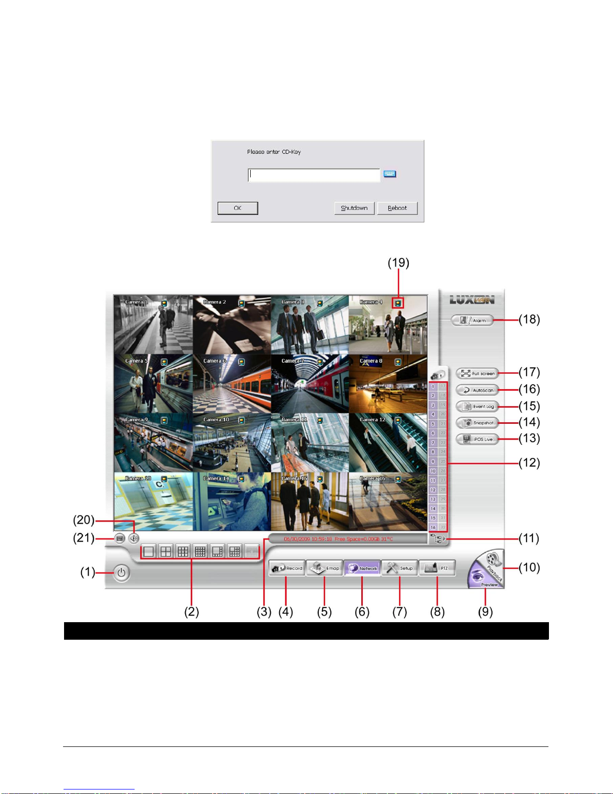
2.1 Running the Unit for the First Time
When the unit is turned on for the first time, the system will prompt you to enter the CD-Key. The CD Key is a
located on REAR PANEL of the unit. If user wants to power off the DVR system, click Shutdown button. To
restart the DVR system, click Reboot button.
2.2 Function buttons in Advanced/Preview Mode
Name
Function
8
Name
Function
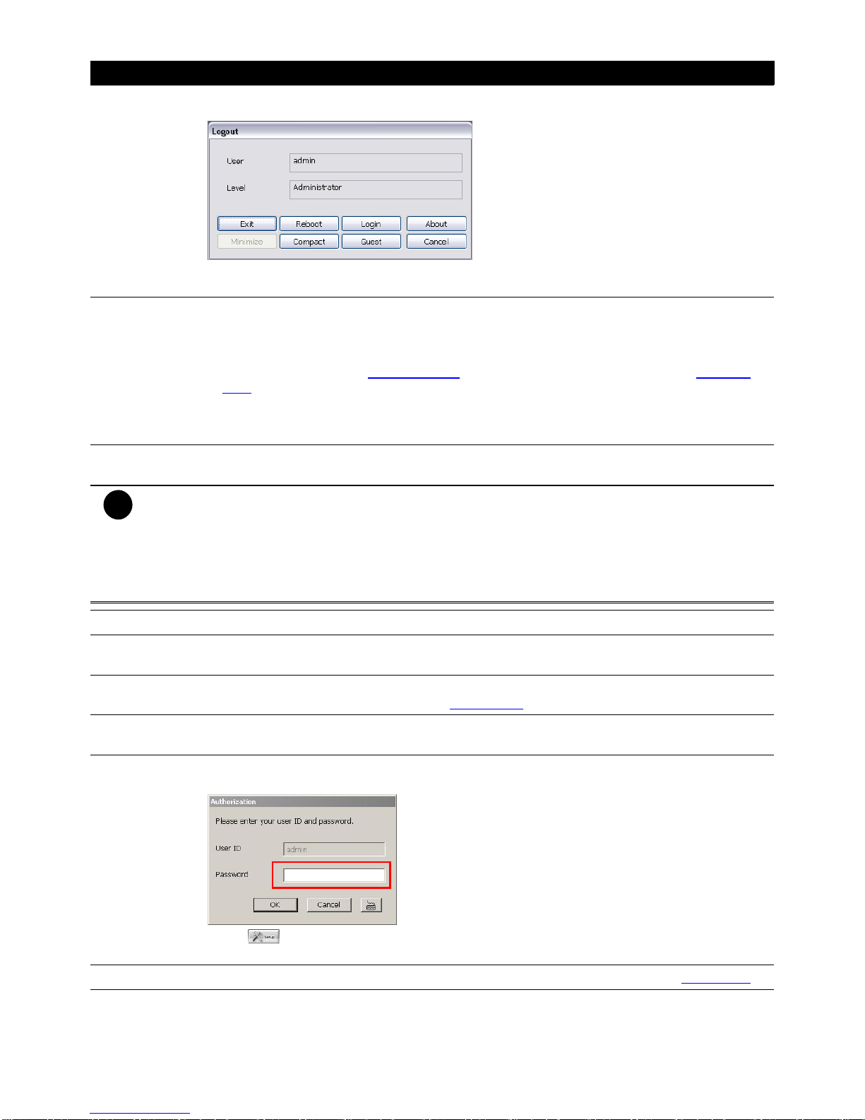
(1) Exit
Call up the Logout dialog box.
In the logout dialog box, you may do the following:
- Exit: To shutdown the DVR program.
- Reboot: Restart the DVR system.
(1) Exit
- Login: To sign-in in different account. Default user ID is admin and password is admin.
- Compact: To switch to compact mode
- Guest: To switch to the guest mode. In guest mode, user only can control DVR by using the
remote control (see also Chapter 2.1.3.1) and the control panel of DVR (see also Chapter
1.4.4). The functions are limited to preview and playback function only. For complete
functions of DVR, please login as an administrator.
- Cancel: To exit Logout dialog box
- About: To update patch or find about the software info.
(2) Split Screen
Mode
It provides 7 kinds of split display modes for your selection. You can select one of the split
display modes by clicking the following icon.
i
- If there are only 4 cameras, you won’t be able to switch to 9, 16, 13, and 32 split screen mode.
- The DVR system will save the current operating mode (split screen mode, auto scan, full screen, and
compact mode status) when shutdown DVR application and apply the mode for next login.
- When you are in single screen mode, Right click and Drag a square on the area you want to enlarge.
- When you are in multiple-screen mode, Right click the video screen of the camera and Drag on where
you want to relocate it. To only display one of the video in the multiple-screen mode, Left click on the
video screen you only want to display.
(3) Status Bar
It shows the current time, system temperature, and the hard disk’s free space.
(4) Record
To start recording. The button turns violet when it is recording. Click it again and enter the
password to stop.
(5) E-Map
To load up to 8 desired E-Maps in BMP or JPG image format, and locate cameras, sensors,
and relays to desired positions (see also Chapter 3.6).
(6) Network
To allow inbound connections. When this function is enabled, the button turns violet. Click it
again to disable all inbound connections.
(7) Setup
When setting up the system for the first time, type the word “admin” in the Password text box
to access.
Click button to configure settings for cameras, recording, network, scheduler, backup,
sensors, relays, alarms and user authentication.
(8) PTZ
To call out a PTZ setup dialog to configure an appointed PTZ camera (see also Chapter 3.5).
(9) Preview
Switch to Preview/Advanced mode. This allows you to view live camera display. Press ctrl + F
can freeze the live preview video screen. And then, click Snapshot can save the freeze video
screen.

9
Name
Function
(10) Playback
Switch to Playback mode. This allows you to view the recorded video file. (see Chapter 3.3)
(11) Camera
Group Tree
To view the user defined channel group tree (see also Chapter 4.2.3). Click + of group to
extend group and drag the camera to surveillance screen to view. Click + of camera to view the
camera information.
(12) Camera ID
Click a desired icon to play the desired channel. After you click the icon, it turns yellow. If you
assign a split display mode and appoint a camera number, the icon group of the cameras will
turn yellow altogether.
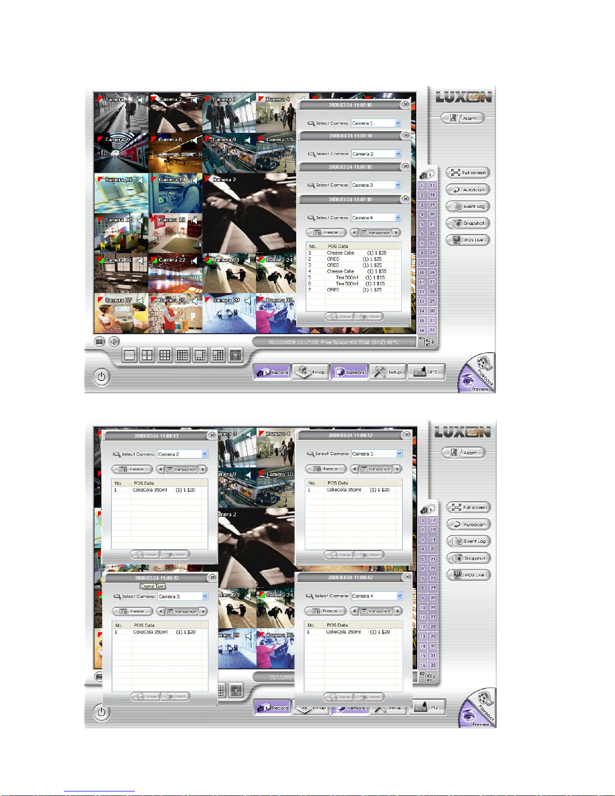
(13) iPOSLive
To view the real time iPOS data of channels. Click the iPOSLive to call out the real time iPOS
data windows.
User can move the each channel of iPOS windows apart to proper position. If user didn’t
enable the multi-channel of iPOSLive( see aslo iPOS Pro Setting in System Setting), and then,
user should only can view one channel each time.
To switch to different channel, click Select Camera drop down list to select the channel. To
tempore stop iPOS data coming, click Freeze. To un-freeze, click Transcation
See images after (21)
(14) Snapshot
Catch a static recording image and save it as a BMP or a JPG file.
(15) Event log
Click it to pop-up the Event Log Viewer dialog to check Event, Operation, POS (Point of Sales),
System and Network logs. You can select a desired date and a log item to show all logs data in
the table.
(16) AutoScan
Click it to start Auto Scan.
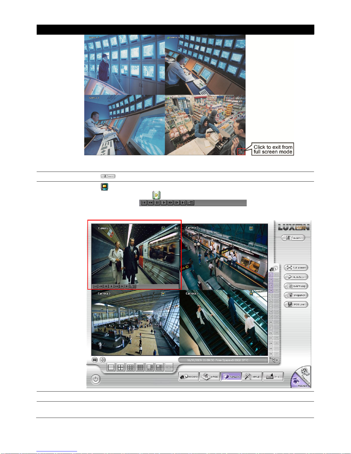
(17) Full screen
Use the entire area of the screen to only display the video. To return, press the right button of
the mouse or ESC on the keyboard or click the arrow icon.
10
Name
Function
When you switch to full screen in multiple-screen mode, Left click to toggle to only display one
of the video in the multiple-screen mode or all.
(18) Alarm
Click to view the status or advanced alarm information.
(19) Live
Playback
button
Click to playback the recorded file instantly in preview mode. When the channel is in live
playback mode, the icon is . Move the mouse to the bottom of the live playback channel,
the playback tool bar ( ) will show up. Using the
playback tool bar to control the playback. Total 4 channels can be live playback at the same
time.
(20) Volume
Adjust the audio volume to a proper volume.
(21) On Screen
Keyboard
If the keyboard is not available, you may use the Virtual Keyboard.
11
(13) iPOSLive Images
12
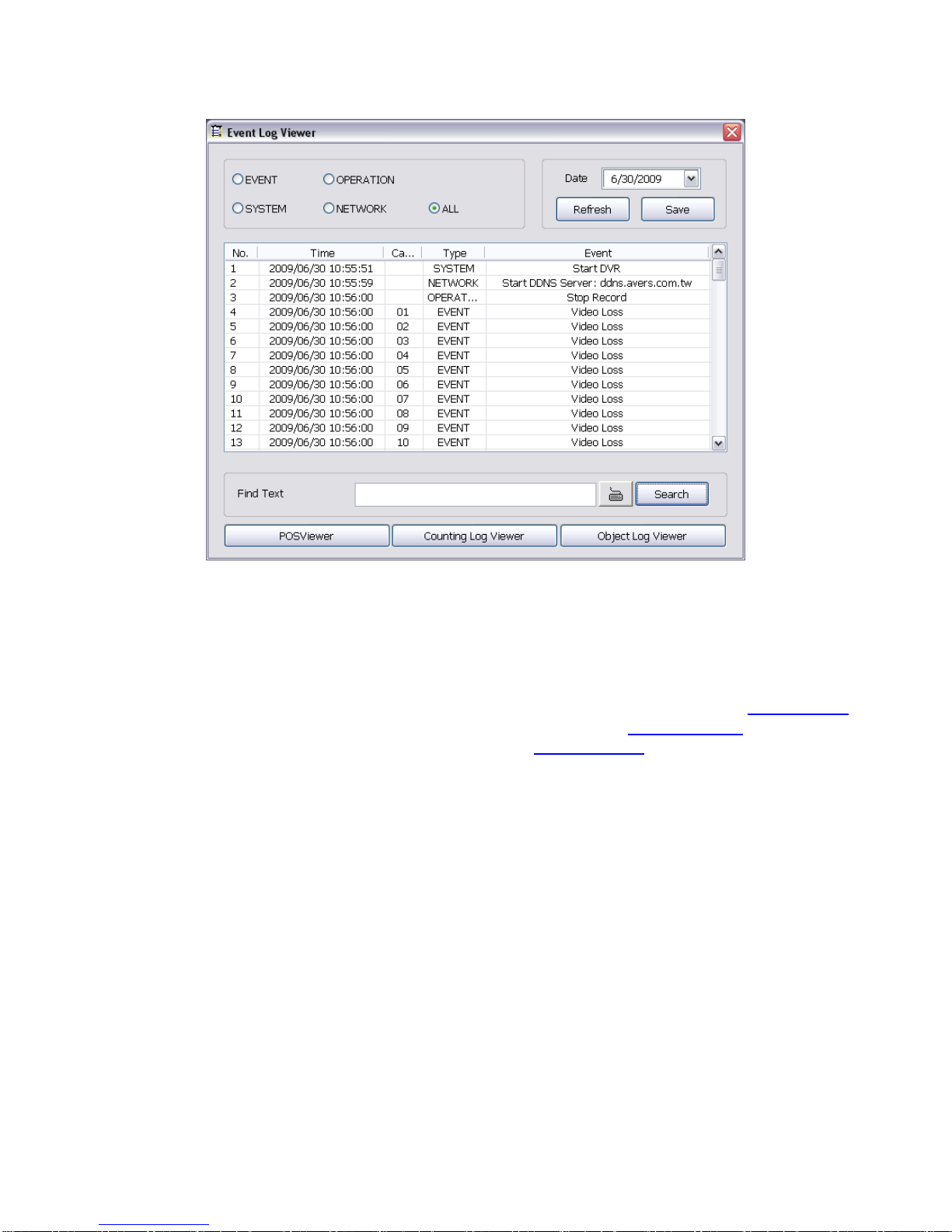
2.2.1 Using Event Log Viewer
Show the record of activities that take place in the system.
1. Click the Event Log button on DVR system main interface. The Event log viewer window will show up.
2. Select the Date to view or search certain event log by key word. Enter the key word in Find Text column
and click Search button.
3. To filter the records, select and click the select button to display Event, System, Operation, Network or
All.
4. The event list which display on the screen can be saved as text file format. To save the event list, click
Save button.
5. To view POS event log, click POSViewer bar to call out the POSViewer window (see also Chapter .2.1.1).
6. Click Counting Log Viewer to view object counting information (see also Chapter 3.2.1.2).
7. To view FaceFinder log, click Object Log Viewer (see also Chapter 3.2.1.3).
13
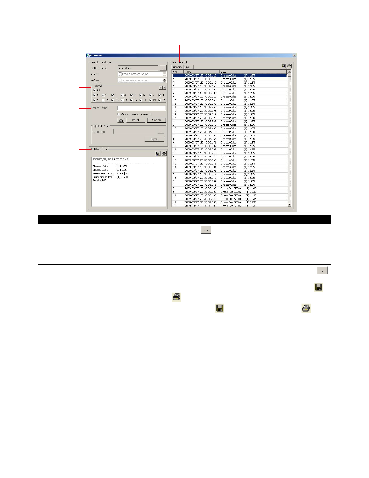
2.2.1.1 Using POSViewer
(1)
(2)
(3)
(4)
(5)
(6)
(7)
Name
Function
(1) POSDB Path
The storage path for POS event log. Click to change the storage path.
(2) Before/After
Set a time period before and after of POS event log.
(3) Channel
Select the POS event log of channel
(4) Search String
Enter specific key word or word string to search the POS event log. Mark the “Match whole
word exactly” box if wants to find exactly key word or word string of POS event log.
(5)Export POSDB
It allows user to save the POS database to selected storage path in excel format. Click
to change the storage path. Click
Export
to save the POSDB to selected storage path.
(6) Full Reception
Display the POS event log detail that user selected from Search Result window. Click to
save the POS event log. Click to print out the POS event log.
(7) Search Result
Display the POS event log of search result. Click to save the search result. Click to print
out the search result.
14
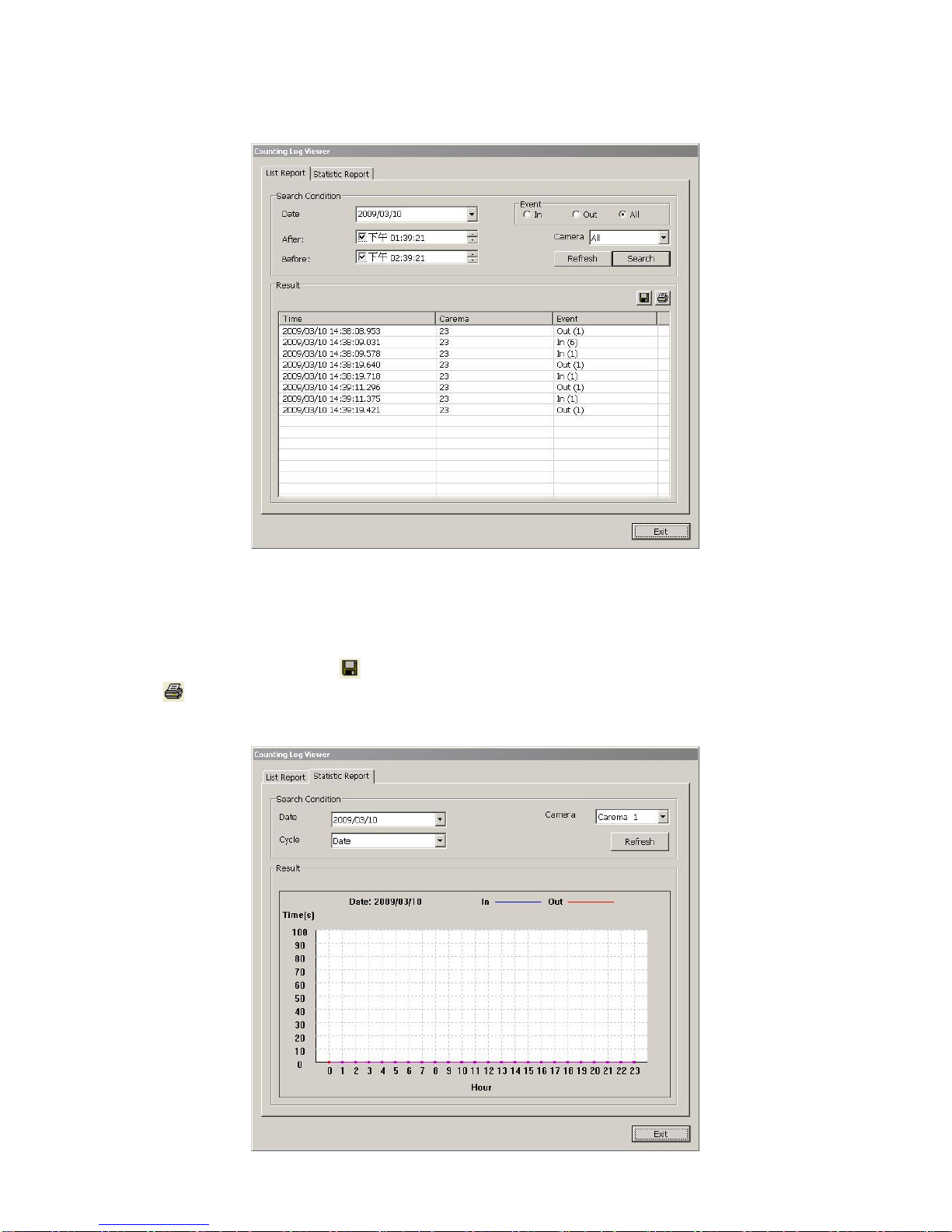
2.2.1.2 Using Counting Log Viewer
Search and view the list and statistic report of object counting. If the object counting function is not enabling,
there will be no any data to view.
1. Select the Date and set a time period between After and Before for object counts searching.
2. Select the search Event – In, Out or All.
3. Select one Camera or All cameras to search.
4. Click Search to start searching.
5. The result will be list out in Result table.
6. To save the search result, click .
7. Click to print out the object counts log list.
8. To view the analysis of object counts, click
Statistic Report
tab.
9. User can select the
Date, Camera
, and
Cycle
to view the report of object counts (In/Out).
15
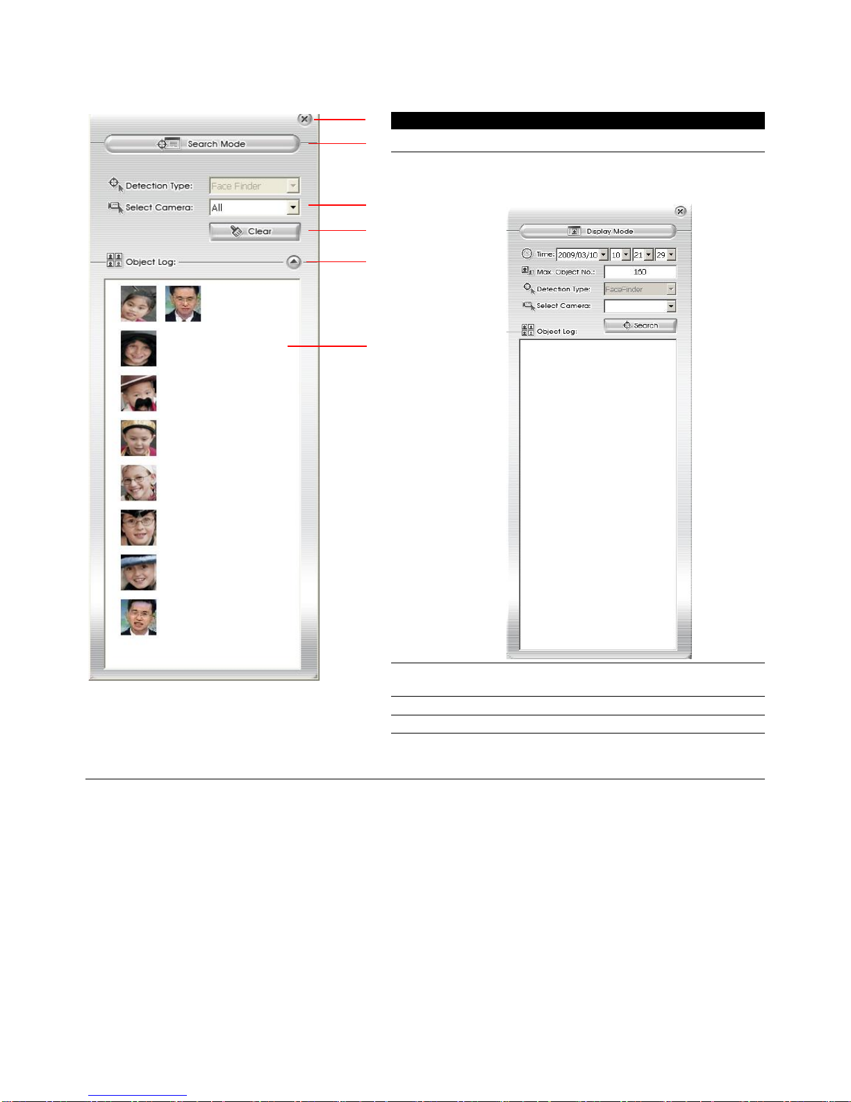
2.2.1.3 Using the Object Viewer
Click Object Viewer bar to view and search FaceFinder event log.
(1)
(2)
(3)
(4)
(5)
(6)
Name
Function
(1) Close
Click to close Object Log Viewer windows
(2) Search Mode
Switch to face object log search mode.
In search mode UI, select the Time and
Camera to search the object.
(3) Select
Camera
Select the camera to view or select all to
view all cameras
(4) Clear
To clear all object log in Object Log list
(5) Close up
Click to close up the Object Log List
(6) Object Log
List
Display the face object logs. It can display
32 object logs and when the list is full, the
first row of object log will be replaced.
16
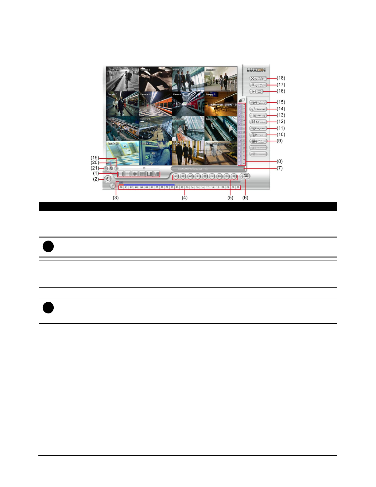
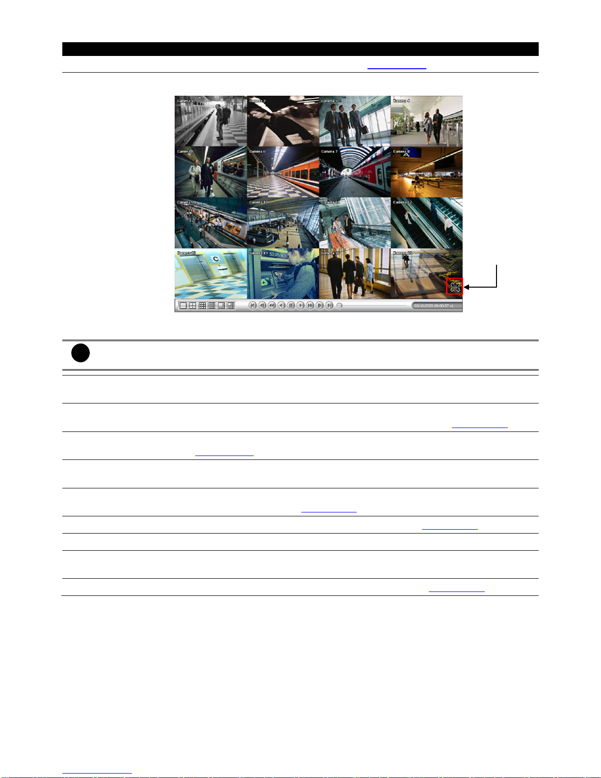
2.3 Function Buttons in Playback Mode
To switch in Playback mode, click Playback button at the lower right corner of Advanced/Preview mode user
interface
Name
Function
(1) Split Screen Mode
Select from 6 kinds of split screen type to playback the recorded video file of all the
camera, or one camera over the other or alongside on a single screen.
To view 32 channels, click 16 split screen button to switch channel display.
i
If there are only 4 cameras, you won’t be able to switch to 9, 13, and 16 split screen mode.
To zoom in an area on the screen, Right click and Drag a square on the area you want to enlarge.
(2) Exit
Close the playback mode and back to preview mode
(3) Progress bar
Show the progress of the file being played. You may move the bar to seek at any
location of the track.
(4) Hour Buttons
Select and click to playback the recorded video file on the specific time frame.
i
The Hour buttons represent the time in 24-hour clock. The blue bar on top of the hour button indicates that
there is a recorded video file on that period of time. While the red bar indicates that you are currently
viewing the recorded video file.
(5) Playback Control
Buttons
Begin: Move at the beginning of the recorded video file.
Previous: Go back to the previous frame.
Slower: Play the recorded video file at the speed of 1/2x, 1/4x, or 1/8x, 1/16x, or 1/32x.
Rewind: Wind back the recorded video file.
Pause: Briefly stop playing the recorded video file.
Play: Play the recorded video file.
Faster: Play the recorded video file at the speed of 2x, 4x, 8x,16x or 32x.
Next: Go to the next frame.
End: Go to the end of the recorded video file.
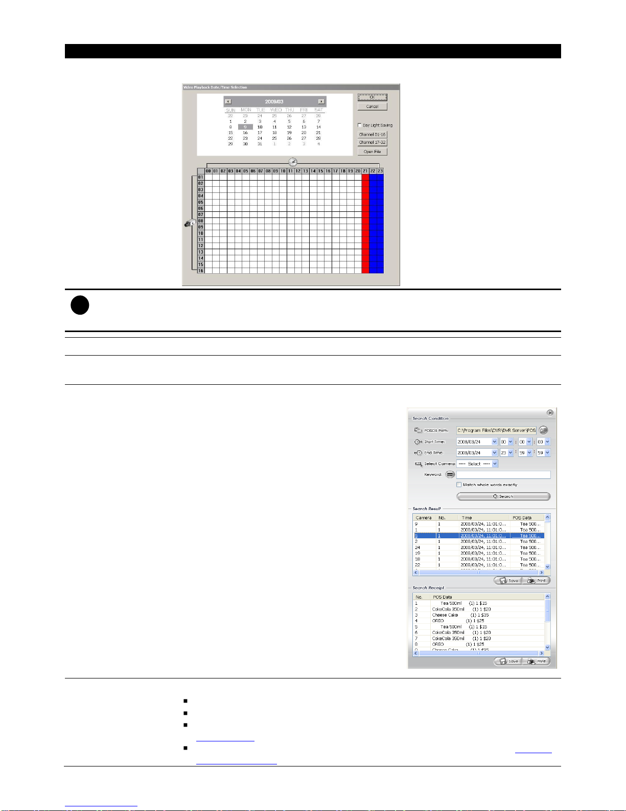
(6) Archive
Select the date on the calendar and the time from 00 to 23 to where to start playing the
recorded video file.
– OPEN FILE: user can open the recorded file from HDD
– Channel 01~ 16&Channel 17 ~ 32: Switch to different channel group of playback
calendar.
17
Name
Function
– Day Light Saving: the playback calendar will show the available video records during
day light saving time period.
i
The numbers from 00 to 23 represent the time in 24-hour clock. The numbers from 01 to 16 represent the
camera ID. The blue colored column indicates that there is a recorded video file on that period of time.
While the red colored column indicates on where to start playing the recorded video file.
(7) Status bar
Display the recorded date, time and play speed.
(8) Camera ID
Show the number of cameras that are being viewed. When you are in single screen
mode, click the camera ID number to switch and view other camera.
(9)iPOS Serach
To find iPOS event by keyword or period.
POSOB Path: where the iPOS data located.
Start Time: select the search start time and date
End Time: select the search end time and date
Select Camera: select the camera for iPOS
events search
Keyword: enter a keyword to search iPOS event
- Match whole words exactly: the iPOS
event must 100% match the keyword
that user has entered.
The search result will display in Search Result
windows. User can click specific iPOS event to
view and the iPOS detail will display in Search
Receipt.
To save the search result, click Save button. Click
Print button to print the search result.
To save the selected iPOS search receipt, click
Save. Click Print to print the selected iPOS
event’s detail.
(10) Export
Export includes Snapshot, Print, Output Video Clip, and Backup function.
Snapshot: Capture and save the screen shot either in *.jpg or *.bmp format.
Print: Print the screen shot.
Output Video Clip: Save the segmented file in *.mpg, *.avi, or *.dvr format (see also
Chapter 3.3.1).
Backup: Save the playback file to USB device or DVD-ROM disk (see also Chapter
4.6 Backup Setting).
18
Name
Function
(11) Segment
Keep a portion of the recorded video (see also Chapter 3.3.1).
(12) Full screen
Use the entire area of the screen to only display the video. To return, press the right
button of the mouse or ESC on the keyboard or click the arrow icon.
When you switch to full screen in multiple-screen mode, Left click to toggle to only
display one of the video in the multiple-screen mode or all.
i
When there are dual monitors with 32 channels, the full screen mode will split into 16 channels on each
monitor.
(13) Event log
Show the record of activities that take place in the system. To filter the records, select
and click the option button to only display Event, System, Operation, Network or POS.
(14) Bookmark
Mark a reference point when previewing the recorded video file to which you may return
for later reference. You may also set it to protect the file. (See also Chapter 3.3.2)
(15) Visual Search
Search from a specific camera by Date, Hour, Minute, 10 Seconds and Second. (See
also Chapter 3.3.3)
(16) Find Next
Search for the next event or changes in the motion detector frame. You can use this
when you are using Intelligent Search or Event Search function.
(17) Event Search
Search from the recorded activities that take place in the system (i.e., Sensor, Motion ,
Video Loss, POS) . (See also Chapter 3.3.4)
(18) Intelligent Search
Search the changes in the motion detector frame (See also Chapter 3.3.5).
(19) Audio
Enable/disable audio sound.
(20) De-interlace
To enhance the video quality. Set the de-interlace mode to #1, if you are capturing
motionless picture and #2, if it captures lots of movement.
(21) Watermark
To verify the playback video has not been modified (also see Chapter 3.3.6)
Click to exit
from full screen
mode
19
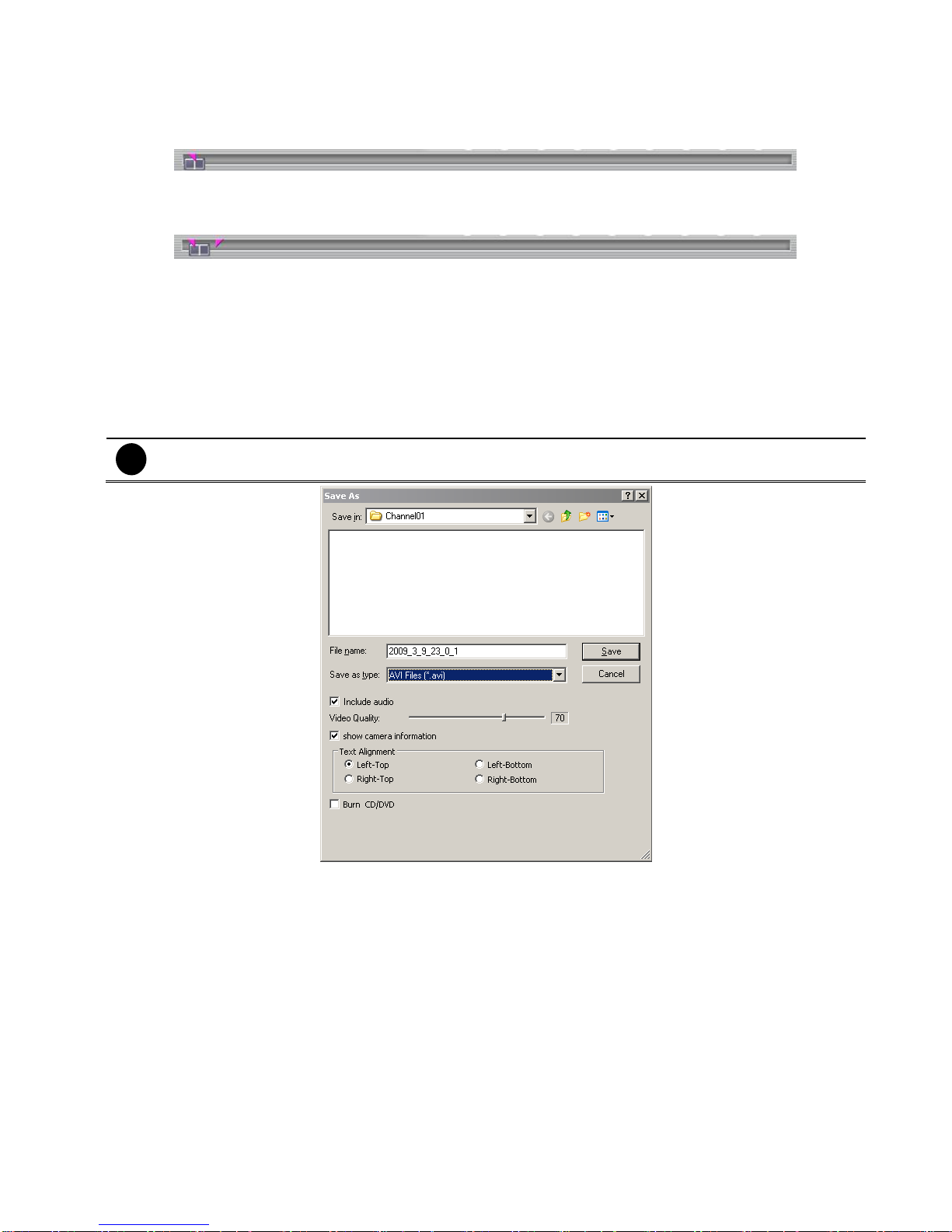
2.3.1 To Cut and Save the Wanted Portion of the Recorded Video
1. Use the Playback Control buttons or drag the bar on the playback progress bar and pause on where
you want to start the cut. Then, click Segment to set the begin mark.
2. Use the Playback Control buttons or drag the bar on the playback progress bar and pause on where
you want to end the cut. Then, click Segment to set the end mark. To cancel segmentation or set the
segment marks from the start, click Segment button again.
3. Click Export → Output Video Clip button to save the wanted clip.
4. In the Save As dialog box, locate on where you want to save the file or choose to Burn the video
segment to CD/DVD ROM (only for .*mpeg file format).
5. Select the file type and select the camera information display position when playback. The camera
information will be the information of server name that user has defined in Network Setting.
6. If the select the file type is *.avi, user can mark Included audio to include audio in output video
segment.
7. To adjust Video Quality if needed.
8. Click Save to save the video segment.
i
Right-click function is disabling for security issue.
20
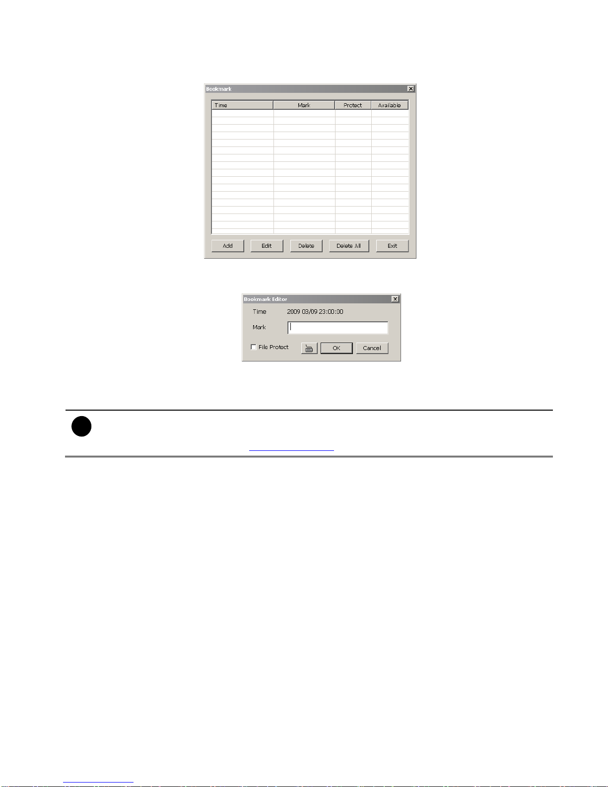
2.3.2 To Bookmark a Section of the Video
1. Click Bookmark. The video playback stops when the bookmark button is executed.
2. In the Bookmark dialog box, you may do the following:
- Add to include the new reference mark in the bookmark list. You may select to enable/disable File
protection.
- Edit to change the mark description or enable/disable file protection.
- Delete to remove the selected reference mark in the list.
- Delete All to remove all the reference marks in the list.
- Exit to close Bookmark dialog box.
i
- When the bookmark is protected, the file won’t be overwritten.
- The protected bookmark file will be deleted when the Delete the recorded data is enable in the
System setting.(also refer to 4.1 System setting)
3. Select and click one in the bookmark list to preview the file.
21
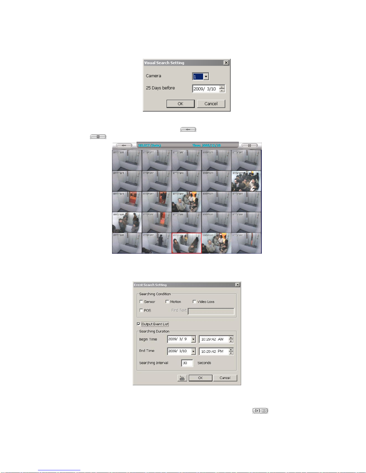
2.3.3 To Search Using the Visual Search
1. Click Visual Search.
2. In the Visual Search Setting dialog box, select the Camera number and the date. Then click OK.
3.
When a series of frames appear by date, click on the frame to display another series of frames and
search by every Hour of that date, every Minute of that hour, every 10 Seconds of that minute, every
Second of that 10 seconds. To go back, click . To view from the selected frame and close event
search, click .
2.3.4 To Search Using the Event Search
1. Click on the video screen on where you want to search.
2. Click Event Search. The Event Search text (red) would appear at the lower left corner of the screen.
3. In the Event Search Setting dialog box, check the type of condition you want to search. If you select
POS, in the Find Text box, type the word. Then, click OK to start searching. The video search would
stop at the frame that matches the condition. To keep on searching click .
4. You may also set to search and list all the result. Just check the Output Event List box. In the Search
Duration section, set the Begin Time and End Time. Set the Searching Interval time for in a period of
time won’t list out the same events. Then, click OK to start searching.
5. When the Event list appear, click and select the item you want to view.
22
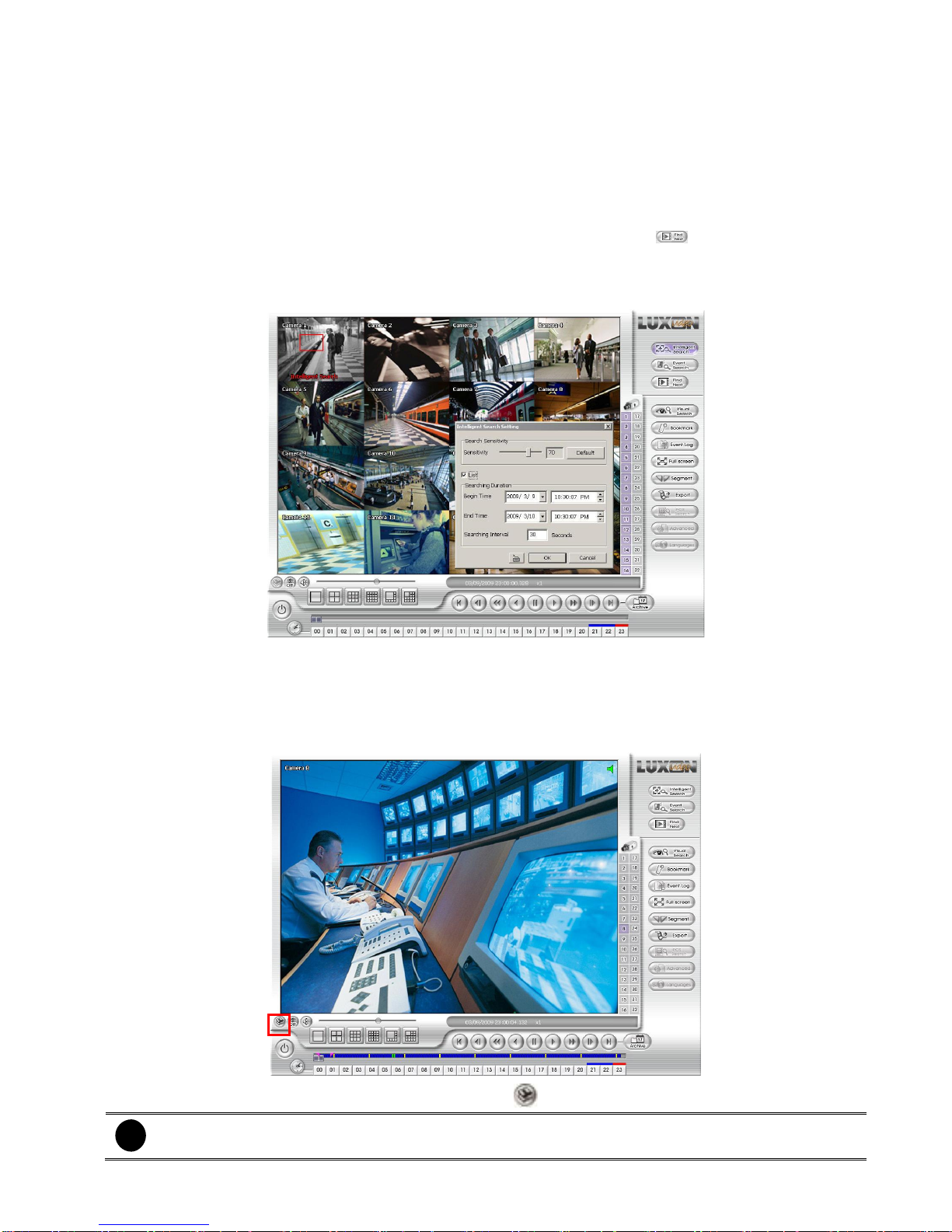
2.3.5 To Search Using the Intelligent Search
1. Click on the video screen on where you want to search.
2. Click Intelligent Search. The Intelligent Search text (red) would appear at the lower left corner of the
screen.
3. When the Intelligent Search Setting dialog box and motion detector frame appear, you may adjust the
sensitivity bar and the motion detector frame size and location. To set motion detector frame size and
location, left click and drag on the screen. Then, click OK to start searching. The video search would
stop at the frame that matches the condition. To keep on searching click .
4. You may also set to search and list all the result. Just check the List box. In the Search Duration section,
set the Begin Time and End Time. Set the Searching Interval time for in a period of time won’t
list out the same events. Then, click OK to start searching.
2.3.6 Watermark Verification
NVR’s support watermark-checking to identify the authenticity of playback video. This program can only
verify when in single channel full screen playback mode. Watermark verification doesn’t support NVR’s with
hardware compression and video that is recorded from IP camera.
To verify the playback video doesn’t been modified. Click to verify the playback video.
i
Watermark verification doesn’t support on hardware compression products and video that is
recorded from IP camera.
23
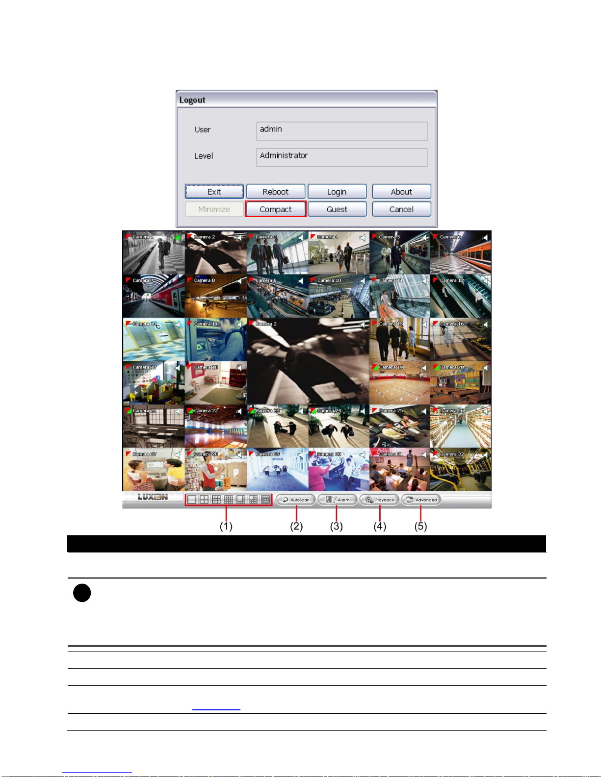
2.4 Function Buttons in Compact Mode
To view in Compact mode, click Exit button. In the logout dialog box, click Compact.
Name
Function
(1) Split Screen Mode
Select from 7 kinds of split screen type to view all the camera, or one camera over the
other or alongside on a single screen.
i
- If there are only 4 cameras, you won’t be able to switch to 9, 16, and 13 split screen mode.
- When you are in single screen mode, Right click and Drag a square on the area you want to enlarge.
- When you are in multiple-screen mode, Right click the video screen of the camera and Drag on where
you want to locate it. To only display one of the video in the multiple-screen mode, Left click the video
screen you want to display.
(2) Auto Scan
Start/Stop video screen cycle switch
(3) Alarm
Alert and display warning info.
(4) Playback
Switch to Playback mode. This allows you to view the recorded video file. (see
Chapter 3.3)
(5) Advanced
Switch to Preview/Advanced mode.
24
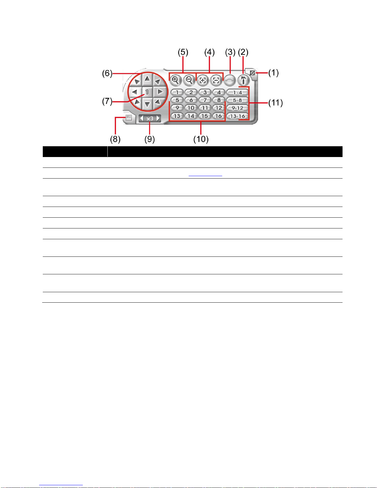
2.5 Function Buttons in PTZ Camera Controller
Name
Function
(1) Close
Exit PTZ camera controller.
(2) Setup
Configure PTZ cameras.(see Chapter 3.12)
(3) AutoPan
Operate the PTZ cameras automatically based on the selected camera group preset
position number.
(4) Focus +/-
Adjust the focus manually to produce clear image.
(5) Zoom +/-
Zoom in and out the image.
(6) Direction buttons
Adjust and position the focal point of the PTZ camera.
(7) Camera ID panel
Display the PTZ camera number that is being operated.
(8) Save Camera
preset position
Save the PTZ camera preset position number. Select the camera and click the preset
position number and save it.
(9) Camera lens speed
controller
Adjust the moving speed of the PTZ camera lens.
(10) Camera preset
position number
Move the PTZ camera to the preset point.
(11) Group AutoPan
Select to automatically operate PTZ camera in group.
 Loading...