

Luxon Video C480WD Owner's Manual
Day & Night Color C amera
Day & Night Color C amera
3
x Digital Zoom
3
x Digital Zoom
WDR Camera Series
OS D
OS D
Thank you for purchasing thisCOLOR VIDEO CAMERA.
Do not install the cam era in extreme temperature condi tions.
Do not install or use the camera in an environment where the
humidity is high.
Do not install the camera under unsta b le lighting conditions.
Never use the camera close to a gas or oil leak.
Do not disassemble the camera.
Do not drop the came ra or subject them to physic al shocks.
Never keep the camera face to strong light directly.
Do not expose the camera to rain or spill beverage on it.
Note
When this camera i s installed near wireless communication
devices tha t emits strong e lectromagnetic f ield, irre
gularity
such as noise on t he monitor may appear.
D
a
y
&
N
ig
h
tC
olor
C
a
m
er
a
D
a
y&
N
i
g
htC
olor
C
a
m
er
a
3
x
Di
gi
ta
lZ
o
o
m
3
x
D
i
gi
t
a
lZ
o
o
m
O
S
D
OS
D
P/N : 3810-0023L
(Ver.0609E)
Design and specifications
are subject to
change without notice.
Color Video Camera Series
e
n
o
Z
y
c
a
v
i
r
P
480
TVL
•
r
e
t
t
u
h
S
w
o
l
S
l
a
t
i
g
i
D
•
)
y
a
l
p
s
i
D
n
e
e
r
c
DIGITAL CAMERA SERIES
a
m
i
c
R
a
n
g
e
)
•
O
S
D
(
S
O
n
COLOR VIDEO CAMERA
OWNER'S MANUAL
On-Screen Display
WDR
WDR
•
W
D
R
(
W
i
d
e
D
y
n
4.Features
1. Wide Dynamic Range (WDR)
SS-II DSP chip built-in SONY allows the camera to find the best picture
conditions in any environment and automatically gives a necessary
light level compensation, so you can always obtain the clear picture,
the finest detail and perfect light contrast.
2. Day & Night
The camera provides automatic mode changeover by sensing day or
night conditions. It can change color mode in the day condition for
optimal color and BW mode in night condition for clear identification.
3. High Resolution
The horizontal resolution of 480TV lines at Color mode can be achieved
by using a high density CCD having Double Speed 410,000 pixels
SONY CCD, which provides clean, noiseless and reliable pictures.
4. Fine Picture Condition Under Very Low Illumination (Sense up)
1/3 high densityCCD and digital processor permit high quality pictures
to be capturedin very low light condition.
5. VIDEO/ MANUAL/ DC Lens Selectable
The camera accepts 3 types of lenses (VIDEO/ MANUAL/ DC) and is
set with the VIDEO/ ELC/ DC selection switch.
6. Electronic Iris
The electronic iris shutter is automatically controlled at the speed of
1/60~1/10,000sec (NTSC Models), 1/50~1/10,000sec (PAL Models)
7. Controlled by OSD menu and RS-485
You can control the camera using OSD menu and RS-485 jack at a remote place.
8. Privacy Zone
8
COLOR VIDEOCAMERA
5.Name and Function
CS-Mount Holding Screw
Used to readjust back focus of the camera. There are two back
focus lock screws. These must be loosened before the camera
may be backfocused.
Loosen the lock screws to turn the CS-mount lens adaptor, and
tighten the lockscrews after adjustment.
Tripod Mounting Hole
Used to installthe camera on an optional tripod. Thetripod
must beequipped with the screw specified asshown below.
1/4"- 20UNC (20 THREAD)
L :4.5mm±0.2mm (ISO standard),
or 0.197"(ASA standard)
C-Mount Lens Adapter
Used to attachC-mount lens.
CS-Mount Lens Adapter
Used to attachCS-mount lens.
Auto Iris Lens Connector
Used toconnect Auto Iris Lens plug.
COLOR VIDEOCAMERA
L
9
.User Information
CAUTION
RISK OFELECTRIC SHOCK
DO NOTOPEN
CAUTION!
TOREDUCE THE RISK OFELECTRIC SHOCK,
DO NOTREMOVE COVER (OR BACK).
NO USER-SERVICEABLEPARTS INSIDE.
REFER SERVICINGTO QUALIFIED
SERVICE PERSONNEL.
Explanation of two Symbols
The lightning flash with arrowhead symbol,
within an equilateral triangle, is intended to
alert the user to the presence of un-insulated
"dangerous voltage" within the product's
enclosure that may be of sufficient magnitudeto constitute a
risk of electric shock to persons.
The exclamation point within an equilateral
triangle is intended to alert the user to the
presence of important operating and
maintenance-(servicing) instructions in the
literature accompanying the appliance.
THE GRAPHICSYMBOLS WITH SUPPLEMENTALMARKING ARE
ON THE BOTTOMOF THE SYSTEM.
"WARNING-TOPREVENT FIRE OR SHOCK HAZARD, DO NOT
EXPOSE THE UNITTO RAIN OR MOISTURE"
2
COLOR VIDEOCAMERA
Model Description
1.
Precautions
2.
Composition
3.
Features
4.
Name and Function
5.
Connection
6.
Remote Controller Operation
7.
Communication Protocol
8.
Operating Camera
9.
Specifications
10.
Troubleshooting
11.
4
COLOR VIDEOCAMERA
INFORMATION
This equipment hasbeen tested and found to comply with limitsfor a
Class A digitaldevice, pursuant to part 15 of the FCCRules.
These limits are designed to provide reasonable protection against
harmful interference when the equipmentis operated in a commercial
environment.
This equipmentgenerates, uses, and can radiate radiofrequency energy
and, if notinstalled and used in accordance withthe instruction manual,
may cause harmfulinter ferenceto radio communications.
Operation of this equipment in a residential area is likely to cause
harmful interference in which casethe user will be required to correct
the interference at theirown expense.
WARNING
The manufacturer couldvoid the user's authority to operate the
equipment.
CAUTION - Toprevent electric shock and risk of fire hazards:
This installation shouldbe made by a qualified service person
and should abideto all local codes.
1.Model Description.Contents
5
6
7
8
9
12
22
24
26
36
42
Before operating the camera, confirm that youhave the right
camera model and proper powervoltage.
In order to help you understand this manual, we'll introduce
our model's description.
Resolution
Signal System
High
High
High
High
High
High
High
High
High
High
High
High
High
High
High
High
When using AC 24V/DC 12V, make sureuse the adaptorover
0.5A for AC 24V, over1A for DC 12V.
Do NOT usepower sources except for that specified.
Do NOT exposethis appliance to rain or moisture.
COLOR VIDEOCAMERA
DAY&NIGHT
AC 240V
AC 240V
COLOR VIDEOCAMERA
WDR
0
0
0
0
0
0
0
0
0
0
0
0
0
0
0
0
X
0
X
0
X
0
X
0
X
0
X
0
X
0
X
0
NTSC
PAL
NTSC
PAL
NTSC
PAL
NTSC
PAL
NTSC
PAL
NTSC
PAL
NTSC
PAL
NTSC
PAL
Power Input
DC 12V
DC 12V
AC 24V /DC 12V
AC 24V /DC 12V
AC 24V /DC 12V
AC 24V /DC 12V
AC 100V~AC 240V
~
AC 100V
DC 12V
DC 12V
AC 24V /DC 12V
AC 24V /DC 12V
AC 24V /DC 12V
AC 24V /DC 12V
AC 100V~AC 240V
AC 100V
~
DC 12V Input Model
Η Function
Setup Button
Λ PowerInput
Terminal
T
() ()
MENU
W
DC12V
AC 24V/DC 12V Input Model
Η Function
Setup Button
Λ PowerInput
Terminal
T
() ()
MENU
W
AC24V/DC12V
()
()
()
()
CONTROL
FG
Class2 Only
V.PHASE
Class2 Only
CONTROL
VIDEOOUT
VIDEOOUT
Θ LensSelection
ELC
Swicth
DCVIDEO
Κ RemoteJack
Μ VideoOut Jack
Θ LensSelection
Swicth
ELC
DCVIDEO
Ι V.PHA SE
Adjustment V.R
Left( ):Internal
Right( ):
External
Κ RemoteJack
Μ VideoOut Jack
AC 100V~AC 240V Input Model
()
Η Function
Setup Button
T
() ()
MENU
()
W
POWERINLET
CONTROL
Λ PowerACIN
3
10
COLOR VIDEOCAMERA
VIDEOOUT
Θ LensSelection
ELC
Swicth
DCVIDEO
Κ RemoteJack
Μ VideoOut Jack
6.Connection
LENS
The lens is not suppliedwith this camera. Purchase a lens suitable
for your environment. This camera accepts the auto iris lens and
both C-and CS-mount lens.
UTP
X
X
X
X
0
0
X
X
X
X
X
X
0
0
X
X
5
Notes
. If the lens ismarked with fingerprints or other marks, the
image quality might be poor.
. It is recommended touse a high quality lens to improve the
image quality under low illumination.
. For using main functionsit is recommended to use
Auto Iris Lens with DCtype.
Installing Auto Iris Lens
1. Peel approximately 8mm fromthe end of the lens cable outer
cover.
8mm
2. Peel approximately 2mm fromthe end of the cable inner cover.
2mm
12
COLOR VIDEOCAMERA
UTP Transmission Model
()
Η Function
Setup Button
Ν UTPVideo
Output Terminal
Η
Θ
Ι
Κ
Λ
Μ
Ν
3. Remove the cover from the iris lens plug supplied, andsolder the lens
cable to theplug as shown below.
Pin.No. VID EO TYP E
1
2
3
4
4. Remove theprotective cap, and attach the lens tothe camera by turning
clockwise.
5. Connect the lens plug to the auto iris connector on the right side of the
camera.
6. Set theVIDEO/ ELC/ DC selection switchto VIDEO or ELC orDC according
to the typeof the lens.
T
MENU
() ()
()
W
RS485 UTP OUT
Function SetupButton
Functions canbe setup using 5 buttonson the camera's rear panel.
MENU Buttons: Used to accessmenu mode.
()
T
Also usedto essape menu mode.
UP/DOWN Buttons: Used to choose thedesired
() ()
MENU
menu item.It also moves the cursorup or down
in themenu screen.
()
W
LEFT/RIGHT Buttons:Used to changethe parameter
of theselected menu item.It also moves thecursor
the left ofright in the menuscreen.
Lens SelectionSwitch
Used to choose DC orVIDEO or ELC accordingto the type of yourLens.
V.PHASE Adjustment V.R(AC 24V / DC 12V InputModel)
If the camera is to be used in LineLockmode, the vertical phase may
require adjustmentto synchronize the vertical phase ofthe camera with
other camerain the system. Makethis adjustment when thever ticalphase
of thecamera does not matchwith other cameras orsystems. For correct
adjustment, usea multi-channel oscilloscope. The V.PHASEadjustment
can bereadjusted.
Remote Jack (Seepage 21)
Used toconnect remote plug.
POWER InputTerminal
Used toconnect an AC 24V or DC12V power source.
Used toconnect a DC 12V power source.
Used toconnect an AC 100V~AC 240V powersource.
VIDEO OUTJack
Used toconnect an external video monitor injack.
UTP VideoOutput Terminal
These terminals providea composite video output signalwhich may be
transmitted overa twisted-pair connection tofurnished with a suitablereceiver.
RED (PowerSource)
N.C
WHITE (VideoSignal)
BLACK (GND)
No. 3Pin
No. 1Pin
No. 4Pin
No. 2Pin
ELC
DCVIDEO
VIDEOOUT
AC24V/DC12V
Class2 Only
COLOR VIDEOCAMERA
Lens cable
connector
()
T
() ()
MENU
()
W
AC24V/DC12V
COLOR VIDEOCAMERA
Θ LensSelection
Μ VideoOut Jack
Λ PowerInput
DC TYPE
--- Damping
--- Damping+
--- Drive+
--- Drive
ELC
V.PHASE
CONTROL
FG
VIDEOOUT
Class2Only
Swicth
Terminal
-
-
DCVIDEO
11
13
2.Precautions
Do use the camera under conditions where temperatures are within
-10¶Cto45¶C.Especially be careful forventilation under high temperature.
It can causethe image quality to be poor.
Severe lightingchange or flicker can causethe camera to work improperly.
It can causemalfunctions to occur.
There are nouser-serviceable parts inside it.
It can causemalfunctions to occur.
It can damageCCD.
If it getswet, wipe it dry immediately. Liquidscan contain minerals that
corrode the electroniccomponents.
6
COLOR VIDEOCAMERA
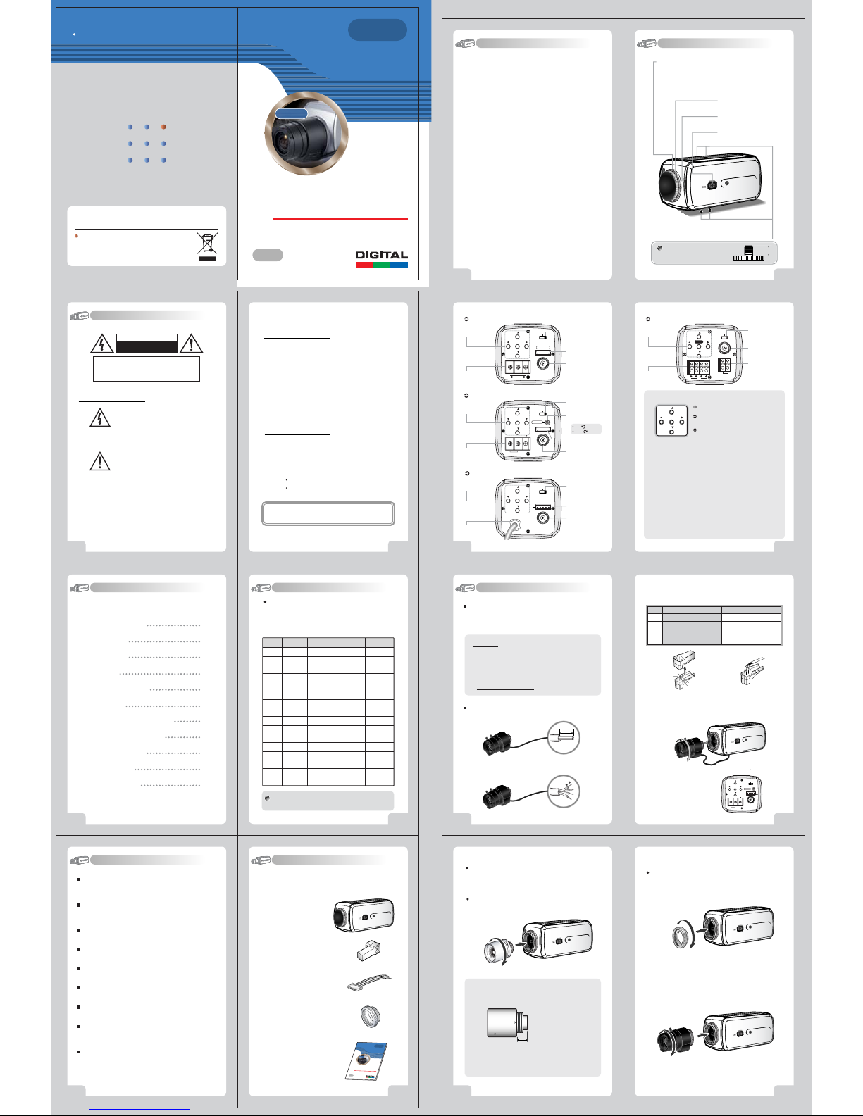
3.Composition
1. WDR Color Video Camera .................
2. Auto Iris Lens Plug ..................
3. Remote Plug ....................
5. C-Mount Adapter ....................
6. Owner's Manual ................
Installing C/CS-Mount Lens
Before mounting a lens, pleasecheck whether it is a C-mount or
CS-mount lens.
The back focus is setfor the CS-mount lens at the factory.
Mounting a CS-Mount Lens
After removing the protectingcap, attach the lens into the camera
by turning clockwise.
Notes
. Use the lens underthe specification as shown. Otherwise the
lens can damage the camera or abnormal fixing may result.
C-mount lens :10mm or less
W
D
W
R
D
e
n
o
Z
y
c
a
v
i
r
P
•
4
8
0
T
V
L
r
e
t
t
u
•
h
W
S
D
w
R
o
l
(
S
W
l
i
a
d
t
i
e
g
D
i
y
D
n
a
•
m
)
y
i
c
a
l
R
p
a
s
i
n
g
D
e
n
)
e
•
e
r
O
c
S
S
D
(
n
O
DI
G
I
T
A
L
C
A
M
E
R
A
S
E
R
C
OLOR
V
I
D
E
O
CA
M
O
WNE
R
'
S
M
A
NUA
O
n
S
c
re
e
n
Di
s
p
l
a
y
COLOR VIDEOCAMERA
R
I
E
S
E
R
A
L
7
. A heavy lens may disturb the balance with the camera and
possibly result in damage.Don't use a lens heavier than 450g.
.
It is recommendedto set the lens ALC mode to Avmode(Average).
Pk mode can be occurred hunting.
14
COLOR VIDEOCAMERA
CS-mount lens :5mm or less
Mounting a C-Mount Lens
1. Attach the C-Mount lensadapter by turning clockwise.
2. Attach the lens tothe camera by turning clockwise.
COLOR VIDEOCAMERA
15

Usually camera I.D. number
are selected from No.1 to No.39.
over I.D. No.40, you will have a use limit.
Copper wire size
(
AWG
)
#18
(
0.83
༅
)
#24
(
0.22
༅
)
#22
(
0.33
༅
)
#20
(
0.52
༅
)
Connecting to Power
Each model hasdifferent power specification, please check thename of
the model andpower specification before connecting to power source.
Please refer tothe sticker identifying the model, whichis attached on the
product, for powerspecification.
For DC 12V PowerType
The wire ispolarized. Be careful of polarity.
Use DC 12V power source.
()
T
ELC
() ()
MENU
CONTROL
()
W
VIDEOOUT
DC12V
Class2Only
Resistance ofcopper wire[at 20
Resistance(Խ
/m
COLOR VIDEOCAMERA
)
)
0.078 0.050
0.028 0.018
Voltage Drop(V/m
. As voltagemay drop according to the length ofelectric cord as above
table, a cameramay malfunction if too long output lineof adaptor is
connected to thecamera.
* Voltagefor camera operation: DC 12V · 10%
* Voltagedrops on above table are variable accordingto types of electric
cord and makers.
16
For AC 24V /DC 12V Power Type
The wire isnon-polarized.
Use AC 24V power source orDC 12V power source.
()
T
ELC
DCVIDEO
() ()
MENU
V.PHASE
()
W
CONTROL
FG
VIDEOOUT
AC24V/DC12V
DCVIDEO
DC12V
Class2Only
(
)]
68ԕF
ఁ
0.018
0.030
0.006
0.011
Class2Only
For AC 24V /DC 12V Power Type [UTP Video Output]
()
T
ELC
MENU
() ()
()
W
VIDEOOUT
RS485 UTPOUT
AC24V/DC12V
Class2Only
When usingAC 24V power, itis possible to supply the powerwithin 100m.
Use 4 wiresby 2 pair of wires.
When using DC12V power, UTP wire cannot be used for power line.
AC24V/DC12V F.G
Class 2Only
DCVIDEO
2Wire
PowerSupply
100m(Max)
AC 24V
COLOR VIDEOCAMERA
17
PELCO "D" Byte Format
Command Message
BYTE 1
MSG
0xFF
BYTE 1
MSG
0xFF
BYTE 1
MSG
0xFF
BYTE 1
MSG
0xFF
BYTE 1
MSG
0xFF
BYTE 1
MSG
0xFF
BYTE 1
MSG
0xFF
BYTE 1
MSG
0xFF
24
COLOR VIDEOCAMERA
BYTE 2
CamID
BYTE 2
CamID
BYTE 2
CamID
BYTE 2
CamID
BYTE 2
CamID
BYTE 2
CamID
BYTE 2
CamID
BYTE 2
CamID
BYTE 3
BYTE 3
BYTE 3
BYTE 3
BYTE 3
BYTE 3
BYTE 3
BYTE 3
0x00
0x00
0x01
0x00
0x40
0x88
0x08
0x00
Zoom TeleFunction
BYTE 4
Zoom WideFunction
BYTE 4
Focus NearFunction
BYTE 4
Focus FarFunction
BYTE 4
Menu On / OffFunction
BYTE 4
Power OnFunction
BYTE 4
Power OffFunction
BYTE 4
Pelco D StopFunction
BYTE 4
BYTE 5
0x20
0x00
BYTE 5
0x40
0x00
BYTE 5
0x00
0x00
BYTE 5
0x80
0x00
BYTE 5
0x00
0x00
BYTE 5
0x00
0x00
BYTE 5
0x00
0x00
BYTE 5 BYTE 6 BYTE 7
0x00
Don't care
BYTE 6
BYTE 6
BYTE 6
BYTE 6
BYTE 6
BYTE 6
BYTE 6
Pelco Keyboard (95+ PATTERN)
BYTE 7
0x00
Checksum
BYTE 7
0x00
Checksum
BYTE 7
0x00
Checksum
BYTE 7
0x00
Checksum
BYTE 7
0x00
Checksum
BYTE 7
0x00
Checksum
BYTE 7
0x00
Checksum
MSG
V/D Keyboard (Set Preset +98)
MSG
BYTE 1
BYTE 1
Menu On / OffFunction
BYTE 2
BYTE 3
BYTE 4
BYTE 5
BYTE 6
BYTE 5
BYTE 7
0x00
0x5F
Checksum
BYTE 6
BYTE 7
0x00
0x62
Checksum
0xFF
CamID
0x00
0x23
Menu On / OffFunction
BYTE 2
BYTE 3
CamID
BYTE 4
0x00
0x03
0xFF
Checksum
COLOR VIDEOCAMERA
25
8.Communication Protocol
Notes
. Be sure to connect power after all the installation is done.
. Note that AC adaptor is not supplied with camera.
. Use only AC 24V / DC12V UL listed class 2 power supply.
. Do not use power sources other than that specified.
For AC 100V ~AC 240V Power Type
()
T
ELC
DCVIDEO
() ()
MENU
()
W
CONTROL
POWERINLET
VIDEOOUT
Cabel
- Brown
AC Power Input
- Blue
- Green
Frame Ground
18
COLOR VIDEOCAMERA
Connecting to Monitor
For UTP Video OutputModel
Connect the UTPvideo output terminal on the back of theproduct to
the monitor.
Camera
()
T
ELC
DCVIDEO
MENU
() ()
()
W
VIDEOOUT
RS485 UTPOUT
AC24V/DC12V
Class2Only
Connect UTP (UnshieldedTwisted Pair) wire to the UTP outputof the
camera directly.
UTP transmitter isincluded in the camera therefore additional UTP
transmitter is notnecessary.
UTP receiver isnecessary to connect UTP wire to Monitoror DVR.
When connecting UTPwire, make sure the polarity of thevideo signal.
Use UTP wire"CAT5 24AWG" to have the best transmissionquality.
The twisted-pair outputcannot be used at the same timeas the
Composite Video output.
20
COLOR VIDEOCAMERA
Monitor(or DVR)
UTPCable
300m(Max)
UTP Receiver
Connecting to Monitor
For BNC Video Output Model
Connect the VIDEOout jack to the monitor video injack.
Camera
()
T
ELC
DCVIDEO
() ()
MENU
V.PHASE
()
W
CONTROL
FG
VIDEOOUT
AC24V/DC12V
Class2Only
As the connectingmethod varies with the instruments, refer tothe
manual supplied withthe instrument.
Connect the cableafter power is turned off.
Set the 75Խ/Hi-Z selection switch as shown below ifyou have an
intermediate device.
CCD Camera
()
T
() ()
MENU
()
W
AC24V/DC12V
Remote Jack
12345
Remote Input Jack (RS485)
It is aterminal that controls the function of the cameraat long distance.
PC Interface
RS-232C TORS-422 Converter
R+
R
-
T+
-
T
Intermediate
Video Receiver
ELC
DCVIDEO
V.PHASE
CONTROL
FG
VIDEOOUT
Class2Only
No. Fun cti on
1
2
3
4
5
TD
Tx+
-
Tx
RD
Rx+
Rx
-
GND
DVR Interface (RS-485 Communication)
R+
-
R
DAY / NIGHT Output
It isthe function that can turnon external IR LED Lampby detecting the sensitivity
on CDSwhen the Day / Nightmode is set "Auto" onthe OSD menu of thecamera.
Day/Night Out
3
GND
4
DAY / NIGHT External Input
It isthe function that can be switchedto DAY Mode orNIGHT Mode by receiving
the Day/Night on/off signal from external lightsensor or IR LED LAMP.
When Day/ Night Mode is set "External" on the OSD menuof the Camera.
GND
4
5
D/NON(EXIT)
TRX+
TRX
5V / 10mA0V: IR LED ON(NIGHT)
Open contact : DAY
Close contact : NIGHT
Monitor
End monitor
COLOR VIDEOCAMERA
R+ (RS-485)
-
(RS-485)
R
DAY/NIGHTOUTPUT "H"
GND
DAY/NIGHTINPUT(EXT) "L"
NAME
1
1.Frame GND
6
2.RD
2
3.TD
7
4.DTR
3
5.Signal GND
8
6.DSR
4
7.RTS
9
8.CTS
5
9.RI
RS-232C D-SubConnector (PC)
-
DVR (RS-485)
: IR LED OFF(DAY)
COLOR VIDEOCAMERA
9.Operating Camera
Configuration of The Menu
CAMERA ID
~
255
ZONE LABEL
NEGA/POSI
SHARPNESS
MIRROR
FREEZE
PROTOCOL
INITIAL
EXIT
WB MODE
RED CONT
BLUE CONT
PUSH AUTO
INITIAL
EXIT
BRIGHTNESS
FLICKERLESS
SHUTTER SPD
AGC MAXSET
MAX FLDSET
INITIAL
EXIT
D/N MODE
LEVEL
FILTERDLY
INITIAL
EXIT
WDR MODE
WDR ELVEL
BACK LIGHT
BLC LEVEL
INITIAL
EXIT
GENERAL
GENERAL
AWB
AE
D&N
WDR
PRIVACY
DISPLAY
INITIAL
EXIT
CAMERA ID
ZONE LABEL
NEGA/ POSI
SHARPNESS
MIRROR
FREEZE
PROTOCOL
INITIAL
EXIT
GENERAL
000
SET
POSI/NEGA
0
~
15
NORMAL,MIRROR,VERTICAL,ROTATE
ON, OFF
DEF,P/D
ON, OFF
AUTO,HOLD, USER
NOT USE(AUTO,HOLD), 1~255(USER)
NOT USE(AUTO,HOLD), 1
NOT USE(AUTO,USER), OFF/PUSE(HOLD)
ON, OFF
0
~
60
ON(PAL:x120,NTSC: x100), OFF
x250, x500,x1000, x2000, x4000, x10000
AGC OFF,LOW,MID, HIGH
OFF,2~20 FLD,40 FLD, 80 FLD, 160 FLD
ON, OFF
AUTO,DAY,NIGHT,EXT
~
200
0
0
~
15 SEC
ON, OFF
ON, OFF
0~15
ON, OFF
0~15
ON, OFF
/
MENU
CAMERA ID
ZONE LABEL
NEGA /POSI
SHARPNESS
MIRROR
FREEZE
PROTOCOL
001
SET
POSI
7
NORMAL
OFF
P/D
ON
GENERAL
AWB
AE
D&N
WDR
19
21
26
COLOR VIDEOCAMERA
Main Menu- GENERAL
Press theMENU button to access the GENERAL mode.
TELE/WIDE
Move upand down
using theTELE/
WIDE button.
1. CAMERA ID
Set 'CAMERAID' to the desired modeusing LEFT( ) or RIGHT( ) button.
Press theMENU button to display the 'GENEARL' and movethe arrow
indicator to 'CAMERAID' using the T or W button.
If the 'CAMERAID' feature is set to 'ON', thename will be displayed on
the monitor.(Main 'DISPLAY' MENU)
28
COLOR VIDEOCAMERA
~
255(USER)
MENU
Can bechanged
using the /
button.
-P/D
(Pelco-D)
- DEF
(Default)
PRIVACY
DISPLAY
INITIAL
EIXT
Setting Up The Menu
Use five setup Menu buttons on Rear side of the camera.
2. ZONE LABEL
Youcan enter up to 10 characters.
Move the curserto character-enter location by using the
LEFT( ) or RIGHT( ) button.
Select the desiredcharacter by usingT,Wbutton.
The factory default charactersare
~
Z,a~z,0~9,~,!,#,*,-,+,/,:,;,?,.,",_,(,),&,%,,,,,
A
EXIT : RETURNto GENERAL MENU
If the 'DISPLAY MENU'feature is set to 'ZONE LABEL - ON', the
name will be displayedon the monitor.
MASK
STARTX
END X
STARTY
END Y
INITIAL
EXIT
CAMERA ID
ZONE LABEL
VERSION
INITIAL
OFF STATE
()
T
() ()
MENU
()
W
AC24V/DC12V
ON, OFF
ON, OFF
ON, OFF
ON, OFF
ON STATE,OFF STATE
ELC
V.PHASE
CONTROL
FG
VIDEOOUT
Class2 Only
COLOR VIDEOCAMERA
1~4
AREA
ZONE LABEL
UP/DN -CHAR SELECT
LE/RI -POSITION
MENU -EXIT
3. NEGA/POSI
Select Nega/Posi.
4. SHARPNESS
Adjust the Sharpnessof the screen.
5. MIRROR
NORMAL : Deactivation
MIRROR : Reverseturn Left or Right.
VERTICAL :Reverse turn Up or Down.
ROTATE: Rotate the Screen to180.
6. FREEZE
Used when pausedVideo is needed.
7. PROTOCOL
P/D: Pelco-D
DEF: Default
8. INITIAL
INITIAL GENERALMODE
9. EXIT
RETURN to MAINMENU
COLOR VIDEOCAMERA
DOWN Button (WIDE)
LEFT Button
UP Button (TELE)
RIGHT Button
DCVIDEO
MENU
27
29
7.Remote Controller Operation (Pelco-D)
The remote controlleris optional item.
Receiver
Power
DC12V, 500mA
RS-485 Signal
1 2 3 4
- WhiteTerminal :
- BlackTerminal :
Cable Connection
Receiver &
Remote Control
Remote Control
Η
Camera Selection
32
5
8
9
A
0
PROG
AUTO
TELE
ZOOM
WIDE
F3
F2
-After camera connects with receiver,
firstly checkcamera I.D.
-Press camera I.D. number(1~39 buttons)
on thetop of wireless remote controller.
Example: ZOOMIN
I.D. No.5:Press 5 +<TELE
I.D. No.15:Press
I.D. No.24:Press
I.D. No.34:Press
Caution :
-Initial camera I.D. numberis set up No.0
Ι
when ittakes out of manufacturer'swarehouse.
Θ
Menu(PROG): Shows/ Hides Menu.
Κ
Ι (
TELE):
Moves up anddown items.
Κ (
WIDE):
Λ (
NEAR):
Set datafor the selected items.
Μ (
FAR):
<F1>
<F2>
<F3>
>
+5 +<TELE
+4 +<TELE
+4 +<TELE
>
>
>
Signal (RS-485)
Pelco-D Keyboard
Η
Θ
Μ
Λ
22
416
7
A
SEQ PAN
FAR
FOCUS
NEAR
F1
COLOR VIDEOCAMERA
Pelco-D/ RS-485
COLOR VIDEOCAMERA
DVR System
Main Menu- AWB
Press theMENU button to access the AWB mode.
1.
Set 'AUTO' tothe desired mode using LEFT( ) or RIGHT( ) button.
TELE/WIDE
'WB' is automaticallyset up between 2500~9500.
2.
Set 'HOLD' tothe desired mode using LEFT( ) or RIGHT( ) button.
TELE/WIDE
If 'PUSH AUTOis selected as 'ON', it fixes upthe value setting the
current WB.
3.
Set 'USER' tothe desired mode using LEFT( ) or RIGHT( ) button.
TELE/WIDE
'WB' gains canbe set by using RED CONT,BLUE CONT.
4. INITIAL
5. EXIT
23
30
COLOR VIDEOCAMERA
AWB
WB MODE
RED CONT
BLUE CONT
PUSH AUTO
INITIAL
EXIT
AWB
WB MODE
RED CONT
BLUE CONT
PUSH AUTO
INITIAL
EXIT
AWB
WB MODE
RED CONT
BLUE CONT
PUSH AUTO
INITIAL
EXIT
INITIAL AWBMODE.
RETURN to MAINMENU.
/
AUTO
NOT USE
NOT USE
NOT USE
ON
HOLD
NOT USE
NOT USE
OFF
OFF
USER
101
60
NOT USE
OFF
Main Menu- AE
Press theMENU button to access the AE mode.
TELE/WIDE
1.
Set 'BRIGHTNESS' tothe desired mode using LEFT( ) or RIGHT( ) button.
0~60 BRIGHTNES Levelscan be adjusted.
2.
Set 'FLICKERLESS' tothe desired mode using the LEFT( ) orRIGHT( ) button.
OFF : Deactivation
ON : 1/100(PALModels), 1/120(NTSC Models)
3.
Set 'SHUTTER SPD'to the desired mode using LIFT( ) or RIGHT( ) button.
NORMAL : Deactivation
X250 : 1/250sec, X500:1/500 sec, X1000:1/1000 sec,
X2000:1/2000 sec, X4000: 1/4000 sec, X10000:1/10000 sec
4.
Set 'AGC MAXSET' to the desired mode using LIFT( ) or RIGHT( ) button.
AGC OFF :Deactivation
LOW : Gain is increased or decreased from 0to 10dB automatically
according to theillumination.
MID : Gainis increased or decreased from 0 to20dB automatically
according to theillumination.
HIGH : Gainis increased or decreased from 0 to30dB automatically
according to theillumination.
5.
Set 'MAX FLD SET'to the desired mode using LIFT( ) or RIGHT( ) button.
OFF,2 FLD ~ 20 FLD, 40FLD, 80 FLD, 160 FLD
6. INITIAL
INITIAL AE MODE.
7. EXIT
RETURN to MAINMENU.
BRIGHTNESS
FLICKERLESS
SHUTTER SPD
AGC MAXSET
MAX FLDSET
INITIAL
EXIT
/
AE
19
OFF
NORMAL
MID
2FLD
ON
COLOR VIDEOCAMERA
31
 Loading...