

LUXOMAT PD9-M-1C-SDB-IP65, PD9-M-1C-SDB-IP65-GH, PD9-S-SDB-IP65-FC, PD9-S-SDB-GH-FC Installation And Operating Instruction Manual
Installation and Operating Instruction for
B.E.G. -
Occupancy detectors
PD9-Master-1C/-Slave-SDB-IP65(-GH)-FC
3.
Settings carried out
using remote control
(optional)
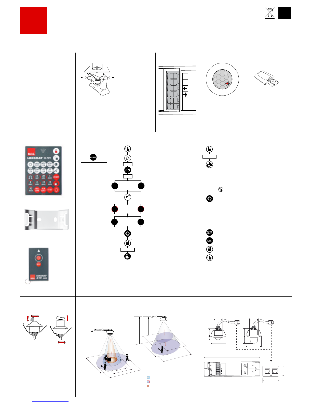
Remote control
LUXOMAT® IR-PD9
Check Battery
:
Open battery compartment
by pressing the plastic springs
together and removing the
battery-holder.
1. Mounting preparations
Work on the 230V mains supply
may only be carried out by qualified
professionals or by instructed persons
under the direction and supervision of
qualified skilled electrical personnel
in accordance with electrotechnical
regulations.
Disconnect supply before installing!
When in Master/ Slave mode of
operation, the Master-appliance
must always be installed at the
location where there is least
daylight.
2a. Installation
4. Option:
Wall bracket for remote control
IR-PD9
The LUXOMAT® PD9-M-1CIP65(-GH) enters an initial
60-second self-test cycle,
when the supply is first
connected. The occupancy
detector is ready for operation.
2c. Self test cycle
IR-PD9
IR-PD-Mini
B.E.G.
LUXOMAT® PD9-M-1C/S-SDB-IP65(-GH)
The detector has
been designed and
developed specifically
for installation in
suspended ceilings.
A circular opening of
diameter min. 32mm
must be produced in
the ceiling.
Having connected the cables in accordance with
the regulations, connect the power supply via the
RJ11 plug. Therefore, open the power supply with
the help of the screws and close it afterwards. After
that, put the power supply through the opening in
the ceiling and mount the sensor onto the ceiling
according to figure.
2b. Connecting
terminals
8. Range of Coverage
In case the sensing area of the
LUXOMAT® PD9-M-1C-IP65(-GH) is too
large or areas are being covered that
should not be monitored, the range
can be reduced or limited through use
of the enclosed masking clips.
7. Exclude sources of
interference
1 Walking across
2 Walking towards
3 Seated
quer zum Melder gehen
frontal zum Melder gehen
Unterkriechschutz
9. Dimensions
GB
5. Settings by remote control
Unlocking device - Activation
of the programming mode
Locking device - Exit programming
mode
Luminance set point for channel 1
20 - 1000 Lux
Automatic reading in the current light
value as new luminance set point
Increase the current light level by
20 resp. 50 Lux
Light ON/OFF
Follow-up time (relay and channel 1)
15sec. - 30 min.
Change between fully automatic
and semi automatic mode (HA)
Daytime operation, detector only
activated by motion
Permanent protection against
sabotage
red LED ashes
Resetting when
open:
Deletes all values
set with the
remote control,
light OFF.
or
1000
20
to
+
to
or
or
6. Key functions in closed state
15
sec
30
min
HA
ON
HA
OFF
22 - 30mm
PD9-SDB-
MASTER-
SENSORHEAD
PD9-SDB-
SLAVE-
SENSORHEAD
N
N
L
L
TEST
12
4
mins
30
25
20
15
12
10
8
6
100
Lux
1500
1000
600
400
200
min. 32mm
154 mm
25 mm
38 mm
45
25
12
16
45
24
25
16
PD9-SDBMASTERSENSORHEAD
PD9-SDBSLAVESENSORHEAD
N
N
L
L
TEST
12
4
mins
30
25
20
15
12
10
8
6
100
Lux
1500
1000
600
400
200
10 m
6 m
4 m
10 m
360°
2.50 m
RJ
2
3
1
6.00 m10.00 m
RJ
360°
6.00 m
6.00 m
3.50 m
3.50 m
PD9-M-1C-SDB-IP65 PD9-M-1C-SDB-IP65-GH
PD9-M-1C-SDB-IP65
PD9-M-1C-SDB-IP65-GH
Permanent protection against sabotage
This function blocks the unit permanently (green LED is
illuminated). This operating mode can only be activated
during the period of 5 seconds after pressing the “lock“
button. This status will only permit actuating the function
“Light on/ Light off”.
The procedure for leaving this mode is as follows:
1. Switch off the current
2. Apply current for 31 – 59 seconds
3. Switch of the current again
4. Apply current
5. Open detector
Light on/off when closed
=> (see page 2, point 11)
The light will remain switched on/ off for as long as
movements are detected in the areas of coverage.
Once the last movement has been detected, the light
will remain on for the duration of the follow-up time as
per setting.
The appliance will then return independently to the
mode selected (Fully or Semi-automatic).
Activation/ Deactivation of the test function
Switches channel off and is immediately active again,
exits all timers, interruption of light measurement
Conrmation
Changes to „open“ state
t < 5 sec.
t < 5 sec.
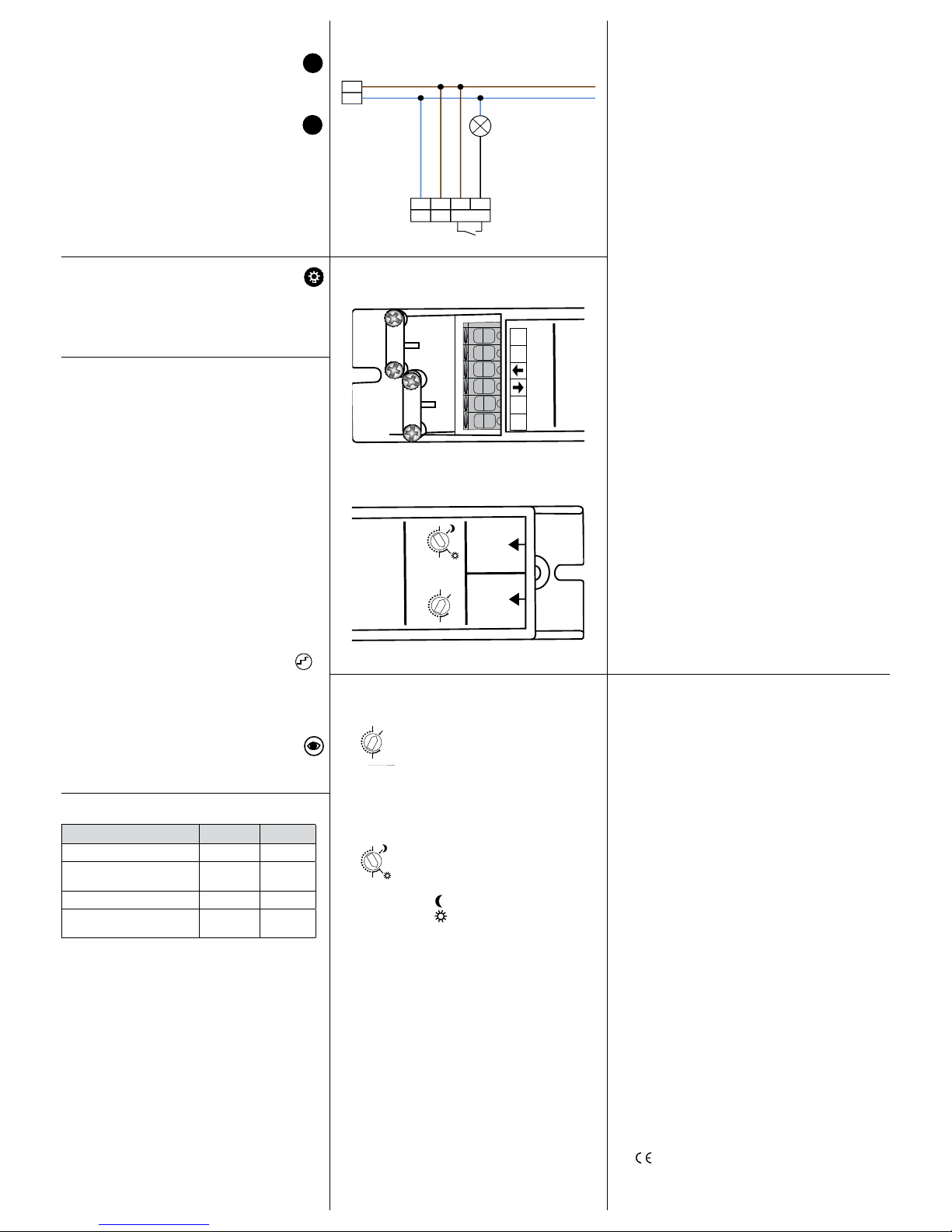
Connection of sensor and power supply by means of
telephone plug RJ11
Power supply: 230V~ ±10 %
Power consumption: < 1W
Ambient temperature: -25°C – +50°C
Degree of protection/class: Detector: IP65 / II / CE
Supply: IP20 / II / CE
Settings: manually or by remote
control
Light values: 10 - 2000 Lux
(remote control)
Extension of the detection area: with PD9-S-SDB
Area of coverage: circular 360°
Range Ø H 2.5m / T= 18°C:
PD9-M-1C-IP65 seated 4 m / tangential
10m / radial 6 m
PD9-M-1C-IP65-GH max. Ø 5.4m
Recommended height for mounting
PD9-M-1C-IP65 2 - 3 m
PD9-M-1C-IP65-GH 5 - 10m
Light measurement: daylight and artificial light
One channel to switch the lighting
Type of contact: NOC/with pretravel
tungsten contact
Contact load: 2300 W, 230 V~,
1150VA cos ϕ= 0.5
Time-settings: 15sec. - 30 min. / Test
(remote control)
Dimensions H x Ø [mm]
Detector Ø 45 x H 40 mm
Visible part Ø 45 x H 12 mm
Power supply L 165 x W 24 x H 24 mm
Technical data PD9-Slave
Electrical data same as above, but just one channel for
signaling motion detection.
Declaration of Conformity: The product complies
with the low voltage recommendation 2006/95/EC
and the EMV recommendation 2004/108/EC.
18. Technical data
14. Wiring diagram
15. Connections
Typ RAL9010 RAL9006
PD9-M-1C-SDB-IP65-FC 92912 92913
PD9-S-SDB-IP65-FC
(only sensor part)
92915
PD9-M-1C-SDB-IP65-GH-FC 92931 92932
PD9-S-SDB-GH-FC
(only sensor part)
92933
LUXOMAT® Remote control:
IR-PD9 (incl. wall bracket) 92201
IR-PD-Mini 92159
Accessory:
Wire basket BSK 92199
Wall bracket for remote control as replacement 92100
Coverring for PD9 white 92238
Coverring for PD9 silver 92237
Coverring for PD9 anthracite 92235
Blind PD9-GH for detection 180° white 33207
13. Article / Part-Nr. / Accessory
11. Manual Switching
You can switch the lighting on and off manually by
pressing the pushbutton for a short time. It will stay on or
off as long as people are detected plus the congured
follow up time.
17. LED-functional indicators, fault-finding
The functional indicators in the case of the LUXOMAT
®
PD9-M-1C-SDB-IP65(-GH) (red and green LED‘s)
Red LED indicating self-checking mode (over a period
of 60 seconds following mains‘-supply lock-on)
Flashing at intervals of 1 second
EEPROM/ memory empty
Flashing rapidly
EEPROM/ memory contains information
Red LED as an indicator of status
Flashing irregularly
Movements are detected within the area of coverage
Flashing regularly
Detector identifies bright, light off
(dependent upon operating mode)
Not illuminated
Detector identifies dark, light on
(dependent upon operating mode)
Flashing extremely rapidly
Too bright / Too dark / Undefined
Red LED as an acknowledgement of receipt for
commands from the remote control
Illuminated for 2 seconds
Signal validly received
Illuminated for 0.5 seconds
Not-accepted command, detector blocked
Flashing extremely rapidly
Not-accepted command, occurs, for example, when an
attempt is made to input twilight-value are too bright or
too dark
Lights up for 3 seconds
Display automatic: Lights up for 3 seconds
Flashing for 3 seconds
Display
semi automatic
Green LED as an indicator of status for
“Permanent protection against sabotage”
Flashing irregularly
Movement are detected within the area of coverage
Flashing regularly
Detector identifies bright, light off
(dependent upon operating mode)
Not illuminated
Detector identifies dark, light on
(dependent upon operating mode)
lluminated for 2 seconds
Signal validly received
(only possible for status “Light on/Light off”)
10. Fully/Semi automatic mode
(for IR-PD9
functions see page 1
)
Fully automatic operation (presence)
In this operating mode, the lighting switches automatically on and off for increased comfort, depending on
presence and brightness.
Semiautomatic operation (absence)
(Semiautomatic can only be activated via the remote
control!)
In this operating condition, in order to gain increased
savings, the lighting is energized only after being manually
switched on.
Switch-off takes place automatically.
The semiautomatic mode basically behaves like the fully
automatic one. However, the difference is that switching-on
must always be carried out manually!
12. Determination of the switch on threshold
to attain a calculatory target value
(for IR-PD9 functions see page 1)
Example:
To do this, rst: open, then select the channel.
Using remote control, you then enter a low Lux value, e.g.
100Lux. The red channel LED ashes quickly and looks “bright”.
You can now approach the switch-on threshold in steps of
20 Lux by repeatedly pressing the step button.
(This only applies to a preselected value of less than 200 Lux.
If the preselected value is above 200 Lux, the threshold is
approached in steps of 50Lux.)
Always take into account the response time of the LUXOMAT®;
each time you press the button, you must wait for 4sec.
Once the correct value is reached, the LED stops ashing.
In this example, 100 Lux is entered and the button is pressed
twice. If the LED goes out, the value seen by the PD9-M-1CSDB-IP65(-GH) is approximately 140Lux.
If the light value actually measured on the working surface is
280Lux, for example, then: 140 : 280 = 0.5 (light distribution
in the room).
If the specied value on the working surface is now to be
500Lux, the LUXOMAT® PD9-M-1C-SDB-IP65(-GH) must be
programmed with a value of 500 Lux * 0.5 = 250 Lux.
In the example, enter 200Lux and then press the button
again.
Steps:
Range 20 - 200 Lux ........ 20Lux/step
Range 200 - 1000Lux ........ 50 Lux/step
If the current luminosity is sufcient,
the button can be used to simply read in the light value
as a brightness switching value (switch-on value).
16. Putting into operation / Settings
Follow-up time for light control
The time can be set infinitely variably at
between 1 and 30min.
Symbol TEST: test mode (every movement
switches on the light for a period of 1 second,
switching it off for a period of 2 seconds after
that regardless of the level of brightness
Twilight-switch for light control (relay 1)
The switch-on value for the light can be set at
between 100 and 1500 Lux. Using the rotary
control, the luminance set points can be set as
desired.
Symbol :
Night-time operation
Symbol :
Daytime/ Night-time operation
Standard mode with master 1-channel occupancy detectors
(NO)
1500
Lux
PD9-SDB-
MASTER-
SENSORHEAD
PD9-SDB-
SLAVE-
SENSORHEAD
N
N
L
L
TEST
12
4
mins
30
25
20
15
12
10
8
6
100
Lux
1500
1000
600
400
200
PD9-SDBMASTERSENSORHEAD
PD9-SDBSLAVESENSORHEAD
TEST
12
4
mins
30
25
20
15
12
10
8
6
100
Lux
1500
1000
600
400
200
HA
ON
HA
OFF
PD9-SDB-
MASTER-
SENSORHEAD
PD9-SDB-
SLAVE-
SENSORHEAD
TEST
12
4
mins
30
25
20
15
12
10
8
6
100
Lux
1500
1000
600
400
200
PD9-SDB-
MASTER-
SENSORHEAD
100
Lux
1500
1000
600
400
200
+
MAN 6272 – 190511-2
 Loading...