

LUXOMAT PD4-M-DALI/DSI-1C-FC Installation And Operating Instruction
Installation and Operating Instruction for B.E.G. - Occupancy detector
PD4-M-DALI/DSI-1C-FC
LUXOMAT
®
PD4-M-DALI/DSI-1C
EN
1. Product information
• Occupancy detector for daylight-dependent lighting
control
• DALI/DSI interface for controlling digitally dimmable
electronic ballasts as a group
• One additional switching channel for controlling lights
and HVAC (heating, ventilation, air conditioning) devices
• Switching between DSI and DALI program by remote
control or DIP switch
• Extension of the detection area by Slave devices is
possible
• Set value brightness, follow-up time – LIGHT/HVAC and
orientation light adjustable
• Manual switching and dimming via pushbutton possible
• Orientation light function
2. Operation
The presence detector controls the light automatically according
to people present (movements) and the ambient brightness.
The integrated light sensor constantly measures the ambient light
and compares it with the set value brightness on the detector. If
the ambient light is sufficient, lighting will not be switched.
If the ambient light level is below the set value brightness, a
movement activates the lighting in the room.
The detector switches the light off despite of a person being present if there is enough natural light for 5 min or if no movement
is detected for one follow-up time.
3. Safety information
Work on the 110-240V mains supply may only be
carried out by qualified professionals or by instructed
persons under the direction and supervision of qualified skilled electrical personnel in accordance with
electrotechnical regulations.
Disconnect supply before installing!
This device is not suitable for disconnection.
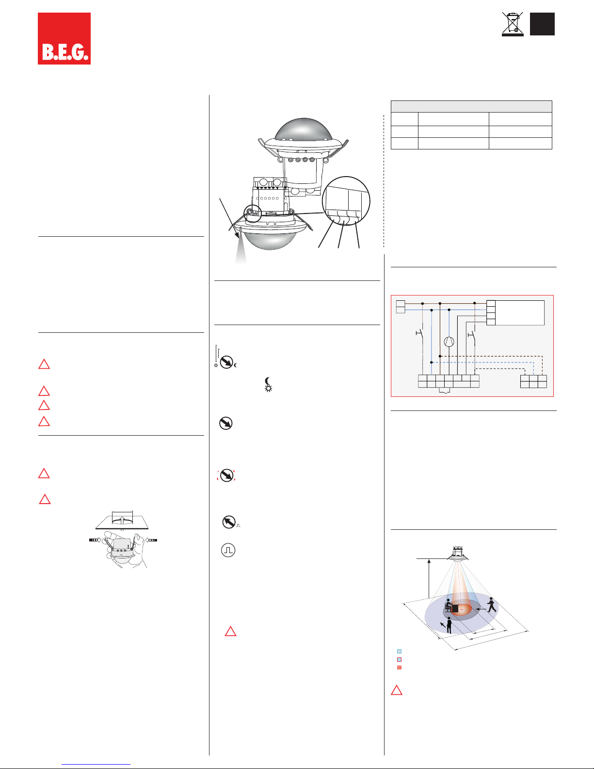
Mounting the cover ring, after introduction of the
power cable (FC version).
4. Mounting
68 mm
A circular opening of diameter 68 mm must be produced in the
ceiling. Having connected up the cables in accordance with
regulations, the detector is inserted into the opening as shown in
the drawing and fixed into position with the assistance of the
spring clips.
5. Position DIP switches, LEDs and
Potentiometers
DALI_DSI
HVAC_
LIGHT VA_HA
PD4-
False ceiling
mounting
Light
measurement
1
2
3
I II III
DCBA
6. Self test cycle/Startup behavior
The product enters an initial 60-second self-test cycle, when the
supply is first connected. During this time the device does not
respond to movement and stays on.
7. Putting into operation / Settings
Brightness value for constant light control
(Potentiometer A)
The brightness set value can be defined between
10 and 2000 lux. The potentiometer enables a free
selection of the brightness value.
Symbol
: Night-time operation
Symbol : Day-time operation
(Light evaluation inactive)
Follow-up time for light control (Potentiometer B)
The follow-up time can be set to 1 to 30 minutes.
Symbol TEST: test mode
Irrespective of the brightness, every movement switches
the light on for 1s, then off again for 2s.
Follow-up time for orientation light (Potentiometer C)
The follow-up time can be set infinitely variably at
between 5 and 60 minutes. Manually switching ON/
OFF the orientation light.
“ON” for permanent orientation light
“OFF” for deactiviation of orientation light
Follow-up time for device control (Potentiometer D)
The follow-up time can be adjusted between 5 min. and
120min. The delay is active from a set time of >15 mi
nutes. This delay is about 5min. If no other movements
are detected during this time, the delay starts again.
Impulse function
The impulse function can be used to control external
HVAC systems. All 9sec. will be set an impulse of
2.5 sec.
Alarm impulse
In order to initiate an alarm impulse, there have to be
three detected movements within a period of 9sec.
This function can be used to display a presence in the
room on external visualizations. All 9sec. will be set an
impulse of 2.5sec.
The device does not fulfil the requirements of DIN
EN50131-2-2 and therefore cannot be used in
professional intrusion detection systems.
DIP switch functions
DIP 1 Full automatic mode Semi-automatic mode
DIP 2 HVAC function Light control*
DIP 3 Operation mode DALI Operation mode DSI
* If you select “LIGHT”, the switching relay R2 operates synchro-
nously to the DALI light channel. The potentiometer R2 has no
function in this setting.
Potentiometer A Brightness (constant light control) channel 1
Potentiometer B Follow-up time (light) channel 1
Potentiometer C Follow-up time (orientation light)
Potentiometer D Follow-up time (device control) channel 2
LED I green
LED II red
LED III white
8. Wiring diagram
Standard mode with Master/Slave
L
N
L
N
N
N
S
Master
Slave
RL
LR
-
+L‘
T1
DA1
M1
T2
DA
DA
E1 DALI/DSI
9.
Manual switching and dimming
By pressing the push button, the phase can be given to the S
terminal.
To turn on or off the light, press the push button briefly. The light
will remain on or off, as long as people are detected plus the
follow-up time.
With a long press of the push button the light will be dimmed
manually. When releasing the button, the current brightness value
is retained.
With renewed long press of the push button, the dimming direction
is reversed.
Taking the phase to the R terminal by using a button, the HVAC
channel can be switched with a short key press.
10. Range
!
Connected Slave devices must have the same phase
as the Master device.
R1
TE
1
3
6
22
18
16
10
30
25
LUX
40
2000
600
1200
200
LUX
40
2000
600
1200
200
R1
TE
1
3
6
22
18
16
10
30
25
LUX
40
2000
600
1200
200
20%
60
5
10
50
30
OFF
ON
!
R1
TE
1
3
6
22
18
16
10
30
25
LUX
40
2000
600
1200
200
R2
A
120
60
5
15
30
40
50
20%
60
5
10
50
30
OFF
ON
A
!
!
!
!
The light sensor should be mounted on the opposite
side of the window.
In Master/Slave operation the Master device must
always be installed at the site with less daylight.
!
!
LEDs
24 m
8 m
6.40 m
24 m
360°
2.50 m
2
1
1
2
quer zum Melder gehen
frontal zum Melder gehen
Unterkriechschutz
Walking across
Walking towards
Seated
3
3
11. Exclude sources of interference
If the detection zone is too large, or areas are covered that should
not be monitored, use the blinds to reduce or limit those areas.
12. Technical data
Power supply: 110-240 VAC, 50/60Hz
Power consumption: approx. 1W
Ambient temperature -25°C to +50°C
Degree of protection/class:
IP20 / II
Recommended height
for mounting:
2 - 3m
Range of coverage
Ø H 2,5 m/T= 18°C:
seated 6.4m / tangential 24m /
radial 8 m
Area of coverage:
circular 360°
Dimensions H x Ø [mm]
FC
103 x 97mm
Visible part when built into ceiling:
15 x 97mm
Lux value:
10 - 2000 Lux
• DALI/DSI
digital BUS control wire, 2-core, no polarity (broadcast only)
Max. no. of series-connected electronic ballasts:
up to 50 (broadcast only)
Time settings:
1 - 30 min. / test
• Channel 2
Type of contact:
NOC/with pre-travel tungsten
contact
Contact load:
2300 W, cosϕ =1;
1150 VA, cosϕ = 0,5, µ contact
Declaration of Conformity:
This product respects the directives concerning
1. electromagnetic compatibility (2004/108/EU)
2. low voltage (2006/95/EU)
3. restriction of the use of certain hazardous substances in electrical
and electronic equipment (2011/65/EU)
13. Article / Part nr. / Accessory
Typ FC
PD4-M-DALI/DSI-1C (Master) 92488
PD4-S (Slave) 92254
LUXOMAT
®
Remote control:
IR-PD-DALI-1C (incl. wall bracket) 92116
IR-PD-DALI-Mini 92112
IR-RC-Adapter with smartphone app 92726
Accessories:
BSK Wire basket 9219 9
14. LED function indicators
LED function indicators
Process
Standard
mode
Double-locked
Initialisation time
unprogrammed
Red flashes
Green flashes
Initialisation time
programmed
Red flashes
quickly
Green flashes
quickly
Motion detection
Red flashes
on each
detected
movement
Green flashes
on each
detected
movement
Too bright detected
Red flashes
2x per
second
Green
flashes
2x per
second
Too bright / too dark /
undefined in opened state
Red flashes
very quickly
Green flashes
very quickly
Toggle DALI/DSI
DSI active
Red shines
3 sec.
Toggle DALI/DSI
DALI active
Green shines
3 sec.
Toggle HA/VA
HA active
White shines
permanently
Toggle Preset/User
Preset active
Red shines
3 sec.
Toggle Preset/User
User active
Green shines
3 sec.
IR signal valid received
Red and
white shine
3 sec.
IR signal invalid received
Red shines
0.5sec.
100 h function active
Red / Green
flash
alternately
Red / Green
flash
alternately
Light measurement in
progress
Green
flashes 1x in
10 sec.
Green flashes
1x in 10sec.
Wall bracket for remote
control IR-PD-DALI-1C
IR-PD-DALI-1C
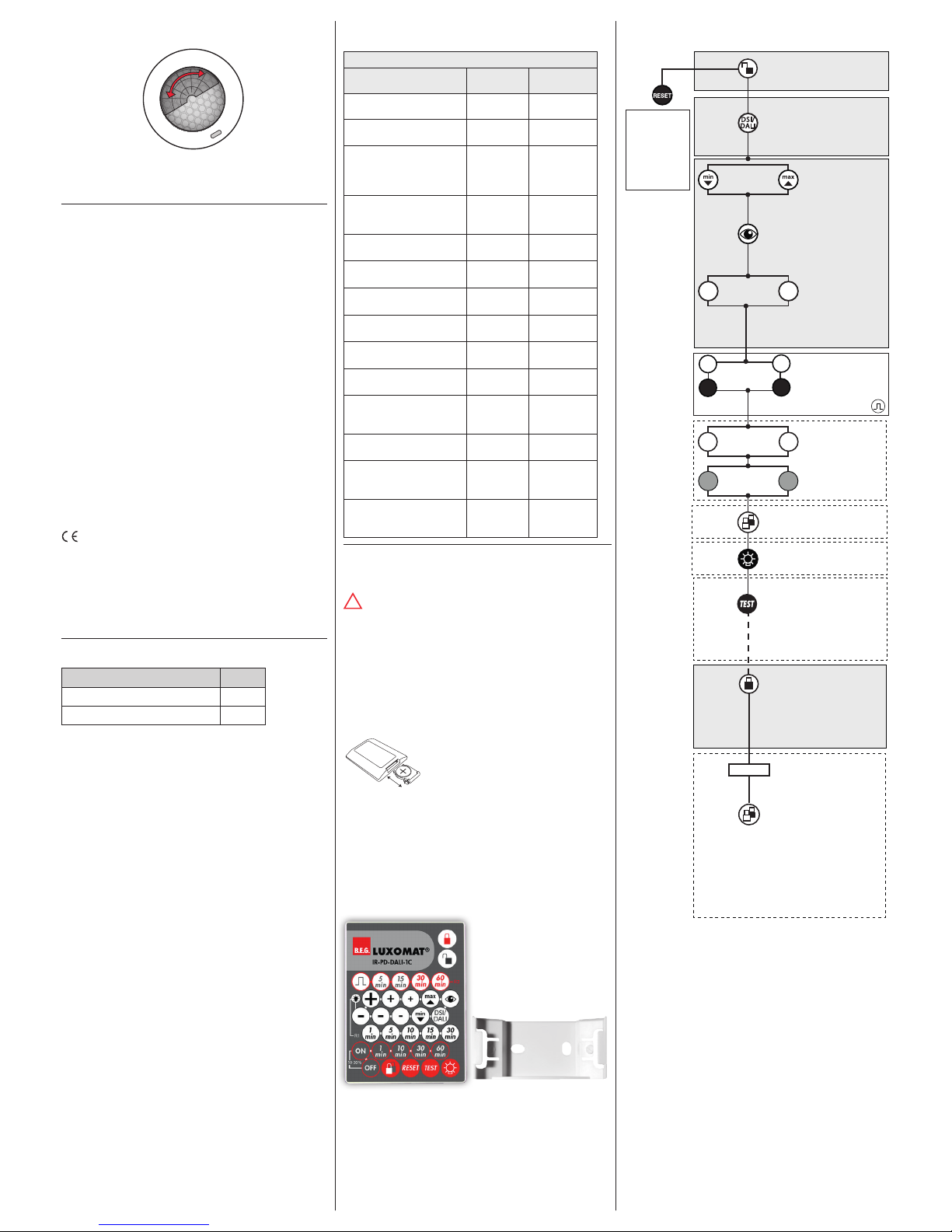
15. Putting into operation of the remote control
(optional)
Settings with remote control override the potentiometer
and DIP settings.
The DIP settings are reactivated by
• setting the potentiometers to “TEST“ and ”SUN” (see
section 24), or
• pressing the “Reset” button on the remote control in
open state
LUXOMAT
®
IR-PD-DALI-1C
1. Check Battery:
Open battery compartment by pressing
the plastic springs together and removing
the battery-holder.
2. Note:
Using the remote control, the occupancy detector can only be
operated brightness-depending. The setting „SUN“ can only be
chosen with potentiometer A.
When using the remote control IR-PD-DALI-1C, we recommand to
set potentiometer A to „SUN“. Pressing the RESET button on the
remote control then resets the detector to brightness-independant
mode (SUN).
!
16. Settings by remote control in open state
Unlocking device –
Activation of the
programming mode
Resetting
when open:
Deletes all
values set with
the remote
control, light
OFF.
Orientation light
on/off
Automatic reading
in the current light
value as new luminance set value
or
Dimming of the
lighting to the
desired brightness
value
Adjusting of the luminance set value from
50 to 1500 Lux:
+/– 5 Lux steps
+/– 10 Lu x steps
+/–
20 Lux steps
max
50
Lux
1500
Lux
ON
OFF
max
50
Lux
1500
Lux
ON
DSI/
DALI
Switching between DSI
and DALI program;
The Factory setting
is DALI
or
+
–
Full automatic /semiautomatic mode (se.18)
Preset/user mode
(see section 23)
Follow-up time
orientation light
at
1
min
10
min
optional
optionaloptional
optional
1. Start light measurement by long
press of the button
(see section 17)
2. Start LED ON/OFF
by a
short press of
the button
Follow-up time
Channel 1: 1 - 30min.
Follow-up time
Channel 2 (HVAC): 5 -
60 min. or impulse
1
min
5
min
30
min
60
min
Exit programming mode
If there is no entry for
about 3min.
the programming
mode is ended
automatically.
Permanent double lock
With this function, the
detector is permanently
locked. This mode can
only be activated during
5 sec. after closing the
detector. In this mode,
only the function „Light
ON/OFF“ can be
activated.
Red LED ashes
optional
t < 5 sec.
 Loading...