

LUXOMAT PD2N-LTMS-RR Installation And Operating Instruction
Installation and Operating Instruction for B.E.G. - occupancy detector PD2N-LTMS-RR-FC
LUXOMAT®PD2N-LTMS-RR
EN
1. Product information
• Multisensor (presence, temperature, brightness detection)
for connection to proprietary bus systems
• Output of the current light and temperature value as
analog voltage
• Low noise Reed Relays
• Other functions via remote control adjustable
2. Operation
The presence detector has sensors for presence;
Temperature and brightness detection which are suitable for
connection to proprietary bus systems. The output of the signals
takes place by analog voltage values 0-10V (10LUX = 0.1 V,
0.5 ° C = 0.1 V) at the output terminals. For evaluating the
motion detection a floating reed relay is still available.
3. Safety information
Work on the mains supply may only be carried out by
qualified professionals or by instructed persons under the
direction and supervision of qualified skilled electrical
personnel in accordance with electrotechnical regulations.
Disconnect supply before installing!
This device is not suitable for disconnection.
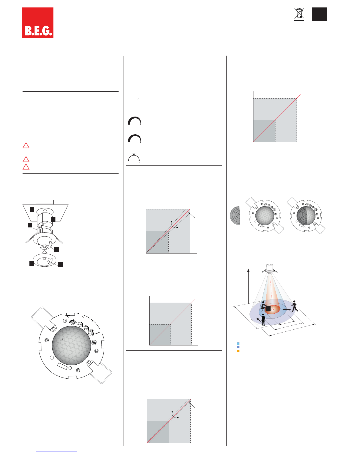
4. Mounting
A circular opening of diameter 68 mm must first of all be
produced in the ceiling.
2
1
2a
4
5
68 mm
3
1) Using the sensor
2) Plug-in ring cover, including
cover for LEDs (2a)
3) Cover slat (if necessary)
4) Protective cover
5) Ceiling
(68 mm diameter hole, drilled)
Having connected up the cables in accordance with regulations,
the detector is inserted into the opening as shown in the
drawing opposite and fixed into position with the assistance
of the spring clip.
5. Hardware configuration FC
Position LED’s and potentiometer
LUX-0
LUX-1
TEMP
30
15
10
5
2
1 min
30s
15s
1s
Potentiometer (A): Potentiometer Follow-up time
Potentiometer (B): Potentiometer Brightness adjustment LUX-0
Potentiometer (C): Potentiometer Brightness adjustment LUX-I
Potentiometer (D): Potentiometer Temperature setting TEMP
LED I: red
Sensor (LUX-0) : Brightness
Sensor
(
LUX-I) : Brightness
Sensor (1): Temperature
6. Self test cycle/Startup behavior
The product enters an initial 60-second self-test cycle, when the
supply is first connected. During this time the device does not
respond to movement and stays on.
7. Putting into operation / Settings
Adjustment follow-up time “motion detection“
TIME
15s
30s
1min.
1s
2
5
10
15
30
The follow-up time can be set from 1 sec to 30 min.
Brightness adjustment LUX-0
LUX-0
The potentiometer LUX-0 can set fine adjustment of
the light output value
Brightness adjustment LUX-I
LUX- I
The potentiometer LUX-I can set fine adjustment of the
light output value
Temperatur Offset
TEMP
+
0
With potentiometer TEMP, an offset can be set
(+4 ° C to -4 ° C)
8.1 Brightness adjustment
With the potentiometers LUX 0 and LUX-I, the output voltage of
the 0-10V output of + / - 10% change and the slope of the lux /
VDC curve can be adjusted. Losses caused by cable lengths can
be compensated.
5 V
10 V
500 lux 1000 lux
LUX
VDC
Potentiometer 2
(LUX)
8.2 Brightness value output as a voltage value`the LUX-terminal
The brightness value output corresponds each 10LUX = 0.1 V
The brightness measurement includes the area between 0LUX =
0V to 10V = 1000 lux
An update of the measured values are approximately every
0.5 s
0
5
10
500 1000
LUX
VDC
8.3 Temperature adjustment
With the TEMP potentiometer output voltage can be offset between -4ºC (-0.8V) to 4ºC (0.8V) regarding to the temperature
measured by the temperature sensor in order to compensate
the measurement of the sensor depending where the device is
placed. The neutral position of the potentiometer is marked with
an arrow where the 0 offset is.
5 V
10 V
25 50
C°
VDC
Potentiometer
8.4 Temperature value output as a voltage value
to the TEMP terminal
The temperature value output corresponds each 0.5 ° C = 0.1
V. The temperature range is the range between 0 ° C = 0 V
and goes to 50 ° C = 10V is done to update the readings
approximately every 10s
0
5
10
25 50
°C
VDC
9. Motion detection
The motion sensor turns on the relay with active motion and turns
off when the unit detects no movement and the follow-up time
has expired. After switching off the motion detection for about
2s is deactivated to prevent an unwanted power up again. An
update of the measured values are approximately every 20ms.
10. Exclude sources of interference
LUX-0
LUX-1
TEMP
30
15
10
5
2
1 min
30s
15s
1s
LUX-0
LUX-1
TEMP
30
15
10
5
2
1 min
30s
15s
1s
+
=
If the detection zone is too large, or areas covered that should
not be monitored, use the blinds to reduced or limited those
areas.
11. Range of Coverage
10 m
6 m
4 m
10 m
360°
2,50 m
walking towards
walking across
seated
1
2
3
1
2
(D)
(A)
(B)
(C)
I
!
!
!
LUX-0
LUX-I
Sensor
Sensor
1
MAN 8353 –PD2N--LTMS-RR–DE_EN–170215–2
12. Technical data
Power supply: 12-48 VDC
Power consumption: < 1W
Ambient temperature: 0°C to +50°C
Degree of protection
/class: IP20 / II
Settings: Potentiometer and
Remote control
LUX-/TEMP-Output: 0-10 V ± 200 mV,
10 mA max.
Light values
Sensitivity: 0 - 1000 Lux, ± 20 Lux
Light measurement: ca.10 mV/Lux
Temperature values: 0°C - +50°C, ± 0,5°C
Sensitivity
Temperature values: ca.200 mV/°C
Area of coverage: circular 360°
Range of coverage
Ø H 2,50 m /
T = 18°C: tangential 10 m /
frontal 6 m
Recommended height
for mounting: 2 - 3 m
Light measurement: mixed light
Motion detector: potential-free contact NO
Contact load: 0-48 VDC, 100mA, cos φ=1
Time setting (Channal 1): Potentiometer
1s. - 30 min.
Remote control
5s - 1h or Impuls function
Connection: single wire (not stranded)
0,34... 1,5mm²
single conductor
Cable length: max. 100m*
*Avoid paralell wiring to power cables. If a separatetd installation is not possible, the use of shielded cables is recommended
Dimensions H x Ø [mm] 83 x 83 mm
Visible portion
when built into ceiling: 20 x 83 mm
Sensor and power supply in one case
Declaration of Conformity:
This product respects the directives concerning
1. electromagnetic compatibility (2004/108/EU)
2. low voltage (2006/95/EU)
3. restriction of the use of certain hazardous substances in electrical
and electronic equipment (2011/65/EU)
13. Article / Part nr. / Accessory
Typ FC
PD2N-LTMS-RR 9 2119
LUXOMAT
®
Remote control:
IR-LTMS (incl. wall bracket) 92185
Accessory:
BSK Ball basket guard 92199
14. LED function displays
LED function indicators
Operating state LED function indicators
Initialization
60s initialization, red ashes 2x in
the second
Active
red lights on when motion is
detected
Resetting the Temperature potentiometer on neutral,
LED lights up for 2 seconds.
15. Connections
X1, X2: Auswertungseinheiten/-geräte
+
-
+
X1
X2
-
NO NO
TEMP
LUX
12-48 VDC
12-48V
0-10V
0-10V
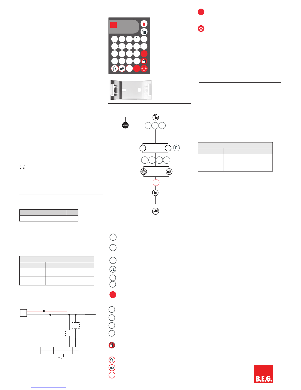
16. Putting into operation of the remote control
IR-LTMS (optional)
IR-LTMS
B.E.G.
LUXOMAT
®
CDS
1
CDS
0
CDS
1+0
5
sec
10
sec
20
sec
30
sec
1
min
5
min
10
min
15
min
30
min
1h
RESET
T++
T+
T--
T-
LED
on/off
TEST
xxxx_IR-LTMS.pdf 1 06.06.2014 12:06:35
IR-LTMS
Wall bracket for
remote control
IR-LTMS
17. Settings by remote control when open
Explanation of the remote control button
functions
CDS
1
Factory setting: In this setting, the light measurement take
place over light sensor LUX-0
CDS
0
In this setting, the light measurement takes place via light
sensor LUX-I
CDS
1+0
In this setting, the light measurement take place over an
average of the two light sensors.
Impuls function
5
sec
1h
Follow-up time
RESET
Reset in the open state: Deletes all values set with the
remote control, Potentiometer settings apply.
Resetting when closed: End all active follow-up Timer
T++
Increase the temperature offset to +1°C (0,2V)
T+
Increase the temperature offset to +0,5°C (0,1V)
T--
Reduce the temperature offset to -1°C (0,2V)
T-
Reduce the temperature offset to -0,5°C (0,1V)
This function permanently blocks the reception of remote
control signals.
This function can be activated within 5
sec. after closing the detector. To unlock see 18. Reset the
permanent sabotage protection
Normal sensitivity
High sensitivity
LED
on/off
Activate or deactivate the LED display
TEST
Test mode, only dependent on movement. With every
movement switches the light for 2 seconds ON, then for 2
sec. OFF. After 3min. Test mode is automatically terminated
and returns to normal operating mode.
To turn the light on and off manually by pressing the button
briey. The light will remain on or off as people are detected plus the follow-up time.
18. Reset the permanent sabotage protection
If the permanent sabotage protection is activated, the detector can
be released again as follows:
• Switch off the power supply and switch it back on
• Switch the power supply off again after 31 seconds of the
initialization and before 59 seconds
• Apply power again and wait for for the self testing
• Press the unlock
19. Selection of the light sensors
The product PD2N-LTMS-RR used a a light sensor, to determine
the brightness value by default, which is located in the outer
cover ring. Through this arrangement, results a selective range,
where the light measurement takes place. For a enlargement of
the selective measurement range, a second light sensor (behind
the lens) can be switched on or get individually activated by the
optional remote control.
Sensor
(
LUX-0) Light sensor in the cover ring (Factory setting)
Sensor
(
LUX-1) Light sensor behind the lens
20. LED-functional indicators
LED function indicators
Operating state LED function indicators
Remote control
signal
LED ashes briey
Detector close LED shines 5 sec.
Resetting
when open:
Deletes
all values set
with the remote
control, light
OFF.
Potentiometer
and DIP
switches
are enabled for
setting.
CDS
1
CDS
0
CDS
1+0
5
sec
to
1h
T++
T+
T--
T-
or
LED
on/off
t < 5 s
X1, X2: Evaluation units/-devices
 Loading...