

Luxlink RJSW-1012 Operating Instructions Manual
WARRANTY
All fiber optic transmission systems, products and accessories
manufactured by Liteway, Inc. and it’s subsidiaries are fully tested
prior to shipment and are warranted against defective materials
and workmanship for a period of five full years from the date of the
original shipment. Should a problem occur, a Return Material
Authorization Number (RMA) must be obtained from Liteway Inc.
at (516) 931-2800 and the item returned to Liteway, Inc. 166
Haverford Road, Hicksville, NY 11801, USA, prepaid. Liteway Inc.
will then, at its option repair or replace the defective item.
Liteway, Inc. maximum liability under this warranty is limited to the
cost of the defective item only. No contingent liabilities of any kind
are either assumed or implied.
Any items returned to Liteway, Inc. that have been misused,
abused, damaged, modified, connected or adjusted in any way
contrary to the instructions furnished by Liteway, Inc. or repaired
by unauthorized personnel will not be covered by this warranty.
Any non-warranty repairs required will be quoted at the current
rate for such services.
!
CAUTION ! AVOID DIRECT EXPOSURE TO BEAM.
All –5, -7, -8, and -9 Models use laser diodes. These solid-state
laser diodes are located in the optical ports of these units. Laser
diodes produce invisible radiation that may be harmful to human
eyes. Never look directly into the optical port of any fiber optic
unit designed to operate with single-mode optical fiber.
NOT FOR LIFE SUPPORT SYSTEMS
Liteway, Inc. does not authorize or warrant any of its products or
accessories for use in critical life support systems or applications
of any kind.
© Copyright 2017 Liteway, Inc. 114219 Rev F
Important Notices
OPERATING INSTRUCTIONS
RJ45 (Cat 6) Switch Box
Model RJSW-1012
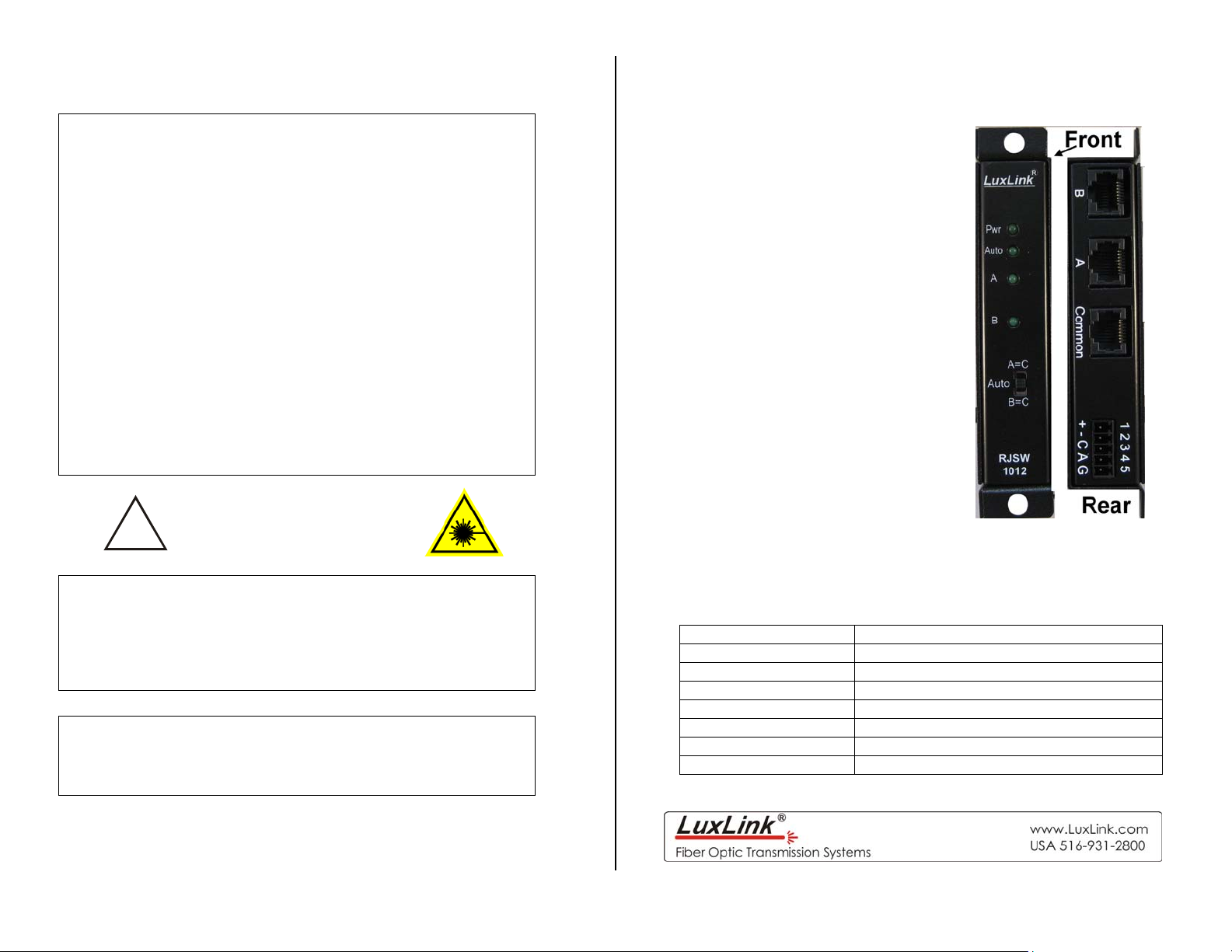
The RJSW-1012 is a two input single output Cat 6 switch. It can be
controlled via the front panel or the terminal block on the rear panel
Technical Specifications
Bandwidth DC to 250 MHz
Switch Over time 10 milliseconds maximum
Compatibility Cat 5, Cat 5e, Cat 6
Indicator Lights Power, Auto, Channel A, Channel B,
Signal Connectors RJ-45
Temperature Range -35º to +75ºC
Power Requirements 11-24 VAC/DC @150 mA
Physical Size (mm) 5.0”(127)L x 1.0” (25.4)W x 3.0”(76)D
All specifications are subject to change without prior notice.
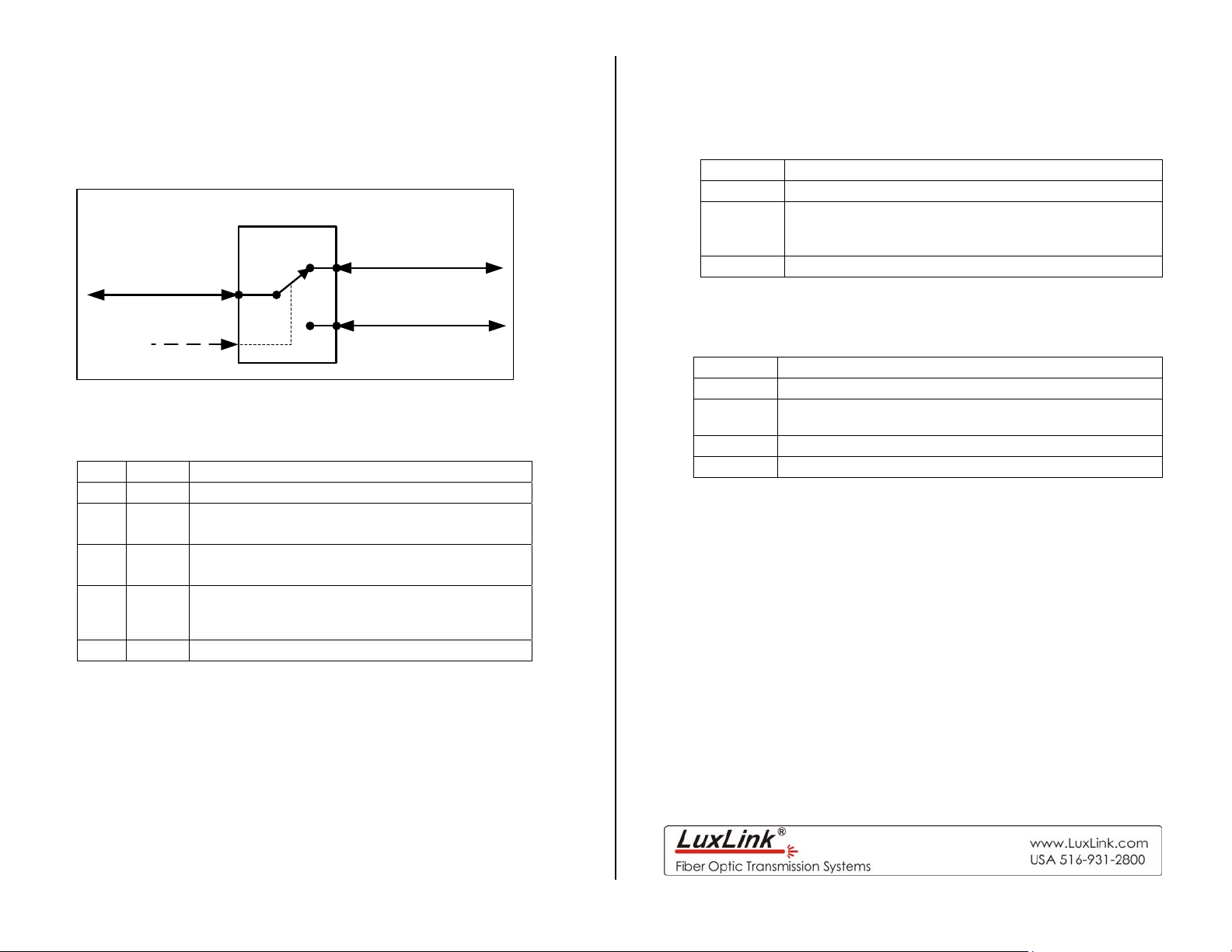
Installation Instructions
The diagram below shows the block diagram of the RJSW-1012. A
one by two Cat 6 switch.
RJSW-1012
Channel A
Channel C
Channel B
Channel
Select
Power Terminal Block Connections
Pin Label Function
1 Pwr+ Power + 11 to 24 volts AC or DC
2 Pwr- Power return (ground)
3 Ctl
4 Alm
5 Gnd Ground
Be certain to check all connections, settings and voltages before
applying power
114219 Rev F
Control signal (Connect to ground to place
switch in bypass state)
Alarm
=gnd when optical switch is in a B=C state
=Open when optical switch is in A=C state
Mode Switch
Setting Function
A=C Forces port A to port C
Auto mode;
Auto
B=C Forces port B to port C
The state of the switch is controlled by the control
signal input on the rear terminal block.
Indicator Lights
Indicator Lights when
Pwr Proper power is present.
Auto
A Port A is connected to Port C
B Port B is connected to Port C
Switch is in auto mode and can be controlled via the
rear panel.
 Loading...