

Luxlink IRGT-1501, IRGR-1501 Operating Instructions Manual
WARRANTY
All fiber optic transmission systems, products and accessories
manufactured by Liteway, Inc. and it’s subsidiaries are fully
tested prior to shipment and are warranted against defective
materials and workmanship for a period of five full years from the
date of the original shipment. Should a problem occur, a Return
Material Authorization Number (RMA) must be obtained from
Liteway Inc. at (516) 931-2800 and the item returned to Liteway,
Inc. 166 Haverford Road, Hicksville, NY 11801, USA, prepaid.
Liteway Inc. will then, at its option repair or replace the defective
item.
Liteway, Inc. maximum liability under this warranty is limited to
the cost of the defective item only. No contingent liabilities of
any kind are either assumed or implied.
Any items returned to Liteway, Inc. that have been misused,
abused, damaged, modified, connected or adjusted in any way
contrary to the instructions furnished by Liteway, Inc. or repaired
by unauthorized personnel will not be covered by this warranty.
Any non-warranty repairs required will be quoted at the current
rate for such services.
!
AVOID DIRECT EXPOSURE TO BEAM.
All -7, -8, and -9 Models use laser diodes. These solid-state laser
diodes are located in the optical ports of these units. Laser
diodes produce invisible radiation that may be harmful to human
eyes. Never look directly into the optical port of any fiber optic
unit designed to operate with single-mode optical fiber.
NOT FOR LIFE SUPPORT SYSTEMS
Liteway, Inc. does not authorize or warrant any of its products or
accessories for use in critical life support systems or applications
of any kind.
© Copyright 2017 Liteway, Inc. 109742 Rev E
Important Notices
CAUTION !
OPERATING INSTRUCTIONS
LuxLink®
Fiber Optic Modulated IRIG
Transmission System
Models; IRGT-1501, IRGR-1501
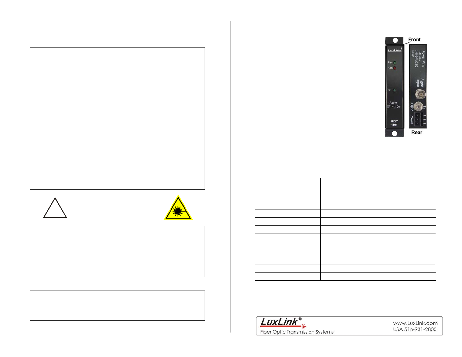
The IRGT / IRGR-1501 system consists of the IRGT-1501
transmitter and IRGR-1501 receiver and will transmit modulated
IRIG signals from one point to another.
Technical Specifications
Signal Bandwidth 100Hz - 500KHz (+0, -3dB)
In/Out Impedance 50 ohms
In/Out Signal Level 3 volt peak to peak (60 mA maximum)
Protocols IRIG A,B,D,E,H; NASA36, IEEE-1344
Signal/Noise Ratio 60 dB/min
Linearity & THD 3% max
Operating Wavelength 850 (-1), 1310 (-3,-7), 1550 (-9)
Optical Loss Budget 0 – 12 dB
Fibers Accommodated 1 multimode (-1, -3), 1 single-mode (-7,-9)
Temperature Range -35º to +75ºC
Power Requirements 11-24 VAC/DC @150 mA
Physical Size (mm) 5.0”(127)L x 3.0”(76)D x 1.0” (25.4)W
System Delays see table at end of manual
All specifications measured with 1Km of 62.5u multimode fiber.
All specifications are subject to change without prior notice.
Installation Instructions
A
A
A
A
A
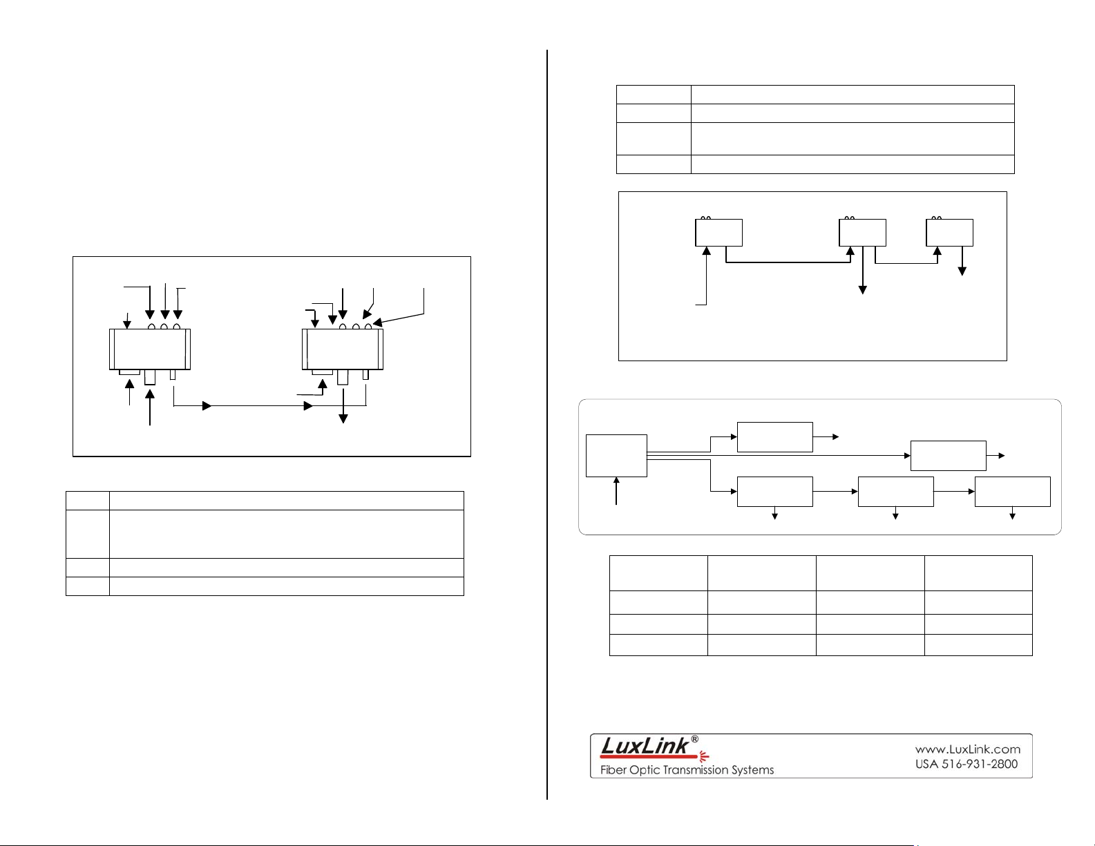
The diagram below shows the typical installation of the IRGT-1501
and IRGR-1501 fiber optic IRIG transmission units. Both should be
connected exactly as shown and an IRIG signal applied to the
transmitter. To compensate for the unique fiber optic losses of your
installation there is a level adjustment on the IRGR-1501. The
receiver level adjustment should then be set for a 3 volt peak to
peak IRIG output signal, or for proper operation of the IRIG terminal
device. The range of the receiver level control is adequate to allow
the full 0 - 13dB optical path loss range to be accommodated.
Signal
larm Switch
larm
Power
Level
djust
larm Switch
Signal
larm
Power
Indicator Lights
Indicator Lights when
Pwr Proper power is present.
Alrm
Sig A IRIG signal is being transmitted or received.
Master
IRIG Source
The loss of signal alarm is activated and there is
no video present
IRGR-1501IRGT-1501
Fiber Optic Cable
IRIG Output
ALM-1000
Alarm
Contacts
IRGT-1001 IRGR-1001
Power
Power
IRIG Input IRIG Output
Fiber Optic Cable
Power Terminal Block Connections
Pin Function
Alarm output for use with optional Alarm Sensing Unit
1
ALM-1000. No other connections should be made to
this terminal
2 +11 to 24 DC or AC Volts i nput
3 AC or DC return (Common to Housing)
Be certain to check all connections, settings and voltages before
applying power
The Alarm switch is used to turn the alarm function on and off.
109742 Rev E
Typical Fiber Optic IRIG Sine Wave System
Typical IRIG Fiber Optic Distribution System
IRGM-1004
IRIG
Transmitter
IRIG
Master In
F/O
Cables
IRGR-1001
IRIG Receiver
IRGP-1001
IRIG Repeater
IRIG Out
F/O
Cable
IRIG Out
IRGP-1001
IRIG Repeater
IRIG Out
System Delays
Transmitter
Receiver
System
850 nm
Multi mode
10 ns 3 ns 1 ns
15 ns 15 ns 14 ns
25 ns 18 ns 15 ns
Note; Be sure to add 1ns per foot of fiber for total delay
1310 nm
Multi Mode
IRGR-1001
IRIG Receiver
F/O
Cable
1310 nm
Single mode
IRIG Out
IRGR-1001
IRIG Receiver
IRIG Out
 Loading...