

Luxibel LX120 User Manual
LX120
LUXIPIX 7X7 LED MA TR IX
USER MANUAL
LX120
V. 05 – 23/07/2014 2 ©Velleman nv
1. Introduction
To all residents of the European Union
Important environmental information about this product
This symbol on the device or the package indicates that disposal of the device after its lifecycle could
harm the environment. Do not dispose of the unit (or batteries) as unsorted municipal waste; it
should be taken to a specialized company for recycling. This device should be returned to your
distributor or to a local recycling service. Respect the local environmental rules.
If in doubt, contact your local waste disposal authorities.
Thank you for choosing Luxibel®! Please read the manual thoroughly before bringing this device into service. If
the device was damaged in transit, do not install or use it and contact your dealer.
2. Safety Instructions
Be very careful during the installation: touching live wires can cause life-threatening
electroshocks.
Always disconnect mains power when device not in use or when servicing or maintenance
activities are performed. Handle the power cord by the plug only.
Indoor use only. Keep this device away from rain, moisture, splashing and dripping liquids.
Never put objects filled with liquids on top of or close to the device.
Keep this device away from children and unauthorized users.
Caution: device heats up during use.
Do not stare directly at the light source, as this may cause
epileptic seizure in sensitive people
temporarily loss of sight (flash blindness)
permanent (irreversible) eye damage.
There are no user-serviceable parts inside the device. Refer to an authorized dealer for service
and/or spare parts.
This device falls under protection class I. It is therefore essential that the device be earthed. Have a
qualified person carry out the electric connection.
Make sure that the available voltage does not exceed the voltage stated in the specifications of this manual.
Do not crimp the power cord and protect it against damage. Have an authorised dealer replace it if
necessary.
Use an appropriate safety cable to fix the device (e.g. VDLSC7N or VDLSC8N).
Install the device at a minimal distance of 0.5 m from flammable and explosive objects or substances.
Respect a minimum distance of 0.5 m between the device’s light output and any illuminated surface.
The maximum ambient temperature is 45 °C. Do not operate the device at higher temperatures.
3. General Guidelines
Refer to the Velleman® Service and Quality Warranty on the last pages of this manual.
Keep this device away from dust and extreme temperatures. Make sure the ventilation
openings are clear at all times. For sufficient air circulation, leave at least 20" (at least 50 cm)
in front of the openings.
Protect this device from shocks and abuse. Avoid brute force when operating the device.
LX120
V. 05 – 23/07/2014 3 ©Velleman nv
Familiarise yourself with the functions of the device before actually using it. Do not allow operation by
unqualified people. Any damage that may occur will most probably be due to unprofessional use of the
device.
All modifications of the device are forbidden for safety reasons. Damage caused by user modifications to
the device is not covered by the warranty.
Only use the device for its intended purpose. All other uses may lead to short circuits, burns, electroshocks,
lamp explosion, crash, etc. Using the device in an unauthorised way will void the warranty.
Damage caused by disregard of certain guidelines in this manual is not covered by the warranty and the
dealer will not accept responsibility for any ensuing defects or problems.
Mechanical wear and LEDs are not covered by warranty.
A qualified technician should install and service this device.
Do not switch the device on immediately after it has been exposed to changes in temperature. Protect the
device against damage by leaving it switched off until it has reached room temperature.
This device is designed for professional use on stage, in discos, theatres, etc.
Use the appropriate power supply (see Technical Specifications below).
Lighting effects are not designed for permanent operation: regular operation breaks will prolong their lives.
Use the original packaging if the device is to be transported.
Keep this manual for future reference.
4. Features
strong die-cast housing
Kling-Net/Art-Net support allows auto-configuration over Ethernet
with bracket for rigging; connection hardware available
auto mode via built-in programs with speed adjustment
master/slave mode for synchronized operation of multiple units linked in a chain
flicker-free operation (400 Hz)
DMX controlled via 5, 49, or 54 channels◦5 channel mode: dimmer, strobe, auto mode, auto mode speed,
dimmer curve
o 49 channel mode: dimmer control for each pixel
o 54 channel mode: dimmer control for each pixel + master dimmer, dimmer curve, shutter, auto mode,
and auto mode speed
clear LCD display for easy operation
power supply via powerCON, linkable
optional bracket: LX121
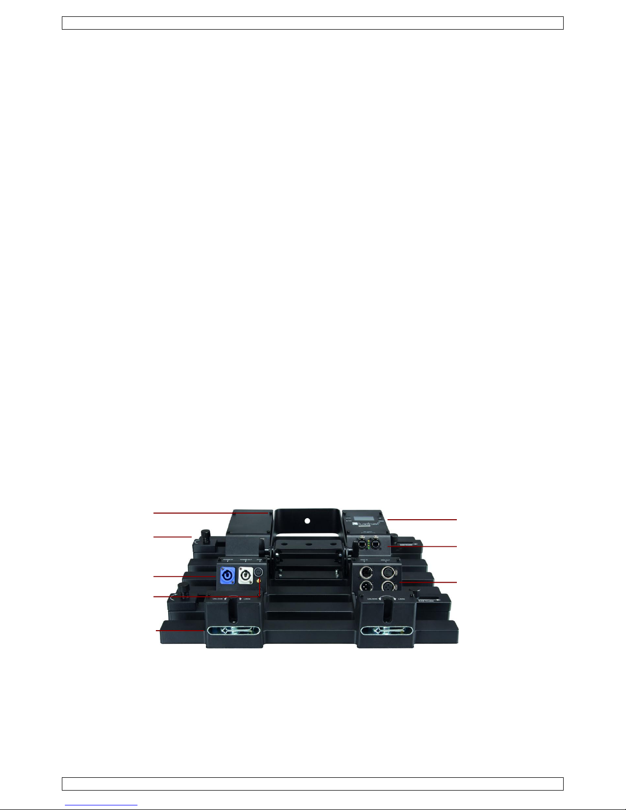
5. Overview
6. Protocols
Kling-Net
ArKaos has designed the Kling-Net protocol to allow the distribution of real-time video data to remote
display devices, such as LEDs or LED panels, over Ethernet.
Kling-Net allows auto configuration of display devices using an etherCON® RJ 45 Ethernet connection.
The device works best with the Arkaos Mediamaster™ Pro software and its Video Mapper extension (Mac and
Windows).
LCD display
signal input/output
(RJ45)
DMX in/out
(3 and 5 pins)
bracket
horizontal
alignment bracket
fuse holder
vertical
attachment
bracket
Neutrik powerCON
in/out
LX120
V. 05 – 23/07/2014 4 ©Velleman nv
Refer to the ArKaos MediaMaster software manual for detailed instructions on programming this product
(www.arkaospro.com).
Art-Net
Art-Net is a communication system that allows DMX512 to be sent over Ethernet.
The Art-Net protocol was developed by the company Artistic Licence Engineering and has now been
published into the public domain.
The protocol description is available on the following link:
www.artisticlicence.com/WebSiteMaster/User%20Guides/art-net.pdf
Various commercial and open source programs support the Art-Net protocol.
7. Mounting
Refer to the illustration in the section Overview above.
Mounting the device
The device can be mounted in almost any orientation.
Mount the device in the desired angle using the included bracket.
Have the device installed by a qualified person, respecting EN 60598-2-17 and all other applicable norms.
The carrying construction must be able to support 10 times the weight of the device for 1 hour without
deforming.
The installation must always be secured with a secondary attachment e.g. a safety cable.
Never stand directly below the device when it is being mounted, removed or serviced. Have a qualified
technician check the device once a year and once before you bring it into service.
Install the device in a location with few passers-by that is inaccessible to unauthorised persons.
Overhead mounting requires extensive experience: calculating workload limits, determining the installation
material to be used… Have the material and the device itself checked regularly. Do not attempt to install
the device yourself if you lack these qualifications as improper installation may result in injuries.
For truss mounting, use an appropriate clamp (not incl.) and fit an M10 bolt through the centre of the
(folded) bracket.
Adjust the desired inclination angle via the mounting bracket and tighten the bracket screws.
Make sure there is no flammable material within a 0.5 m radius of the device.
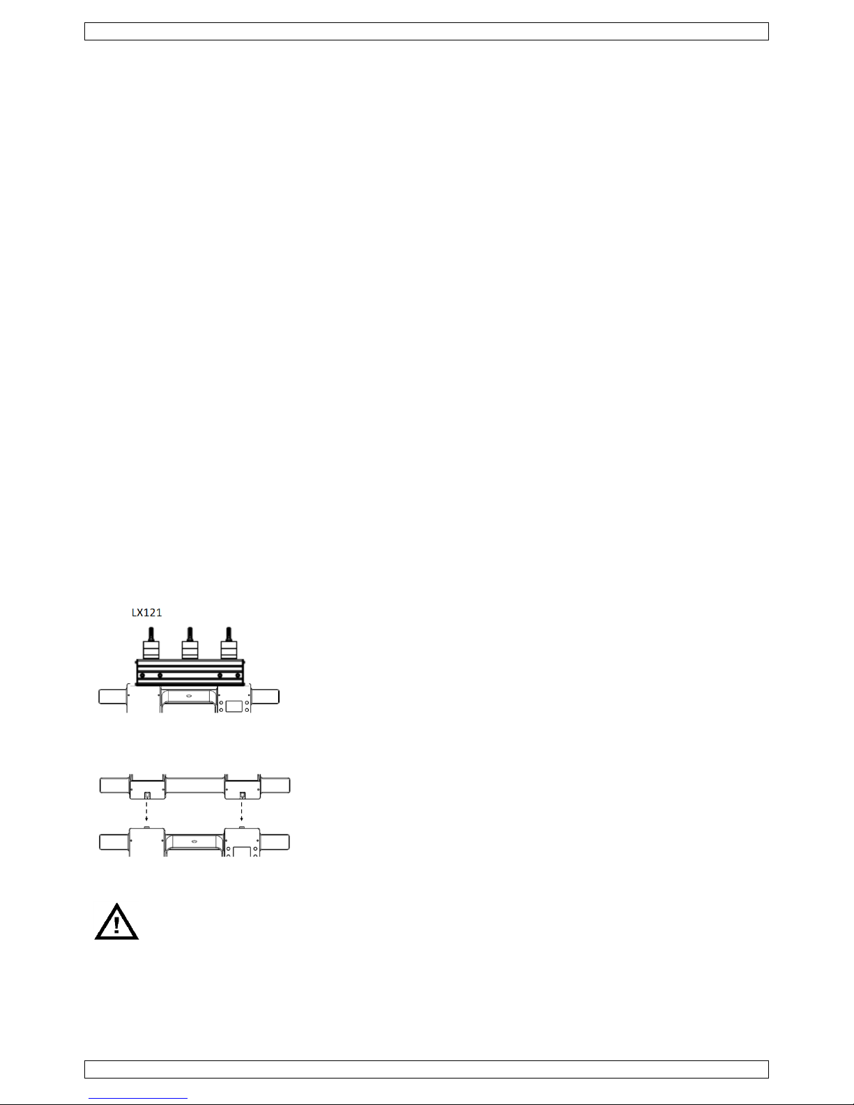
Vertical mounting with optional LX121 bracket
You can hang up to 16 panels vertically using the optional bracket (order
code LX121).
Attach the other panels with the locks at the top and bottom of each
panel.
Vertical mounting without LX121 bracket
If you do not use the LX121 bracket, you can attach up to 4 panels
vertically in a single column using the appropriate clamps.
Position the bracket [1] upwards and attach it using the appropriate
clamps.
Horizontal alignment
The device has brackets for horizontal alignment.
These brackets are for alignment purposes only and cannot be used to support the device.
Additional hardware is required for horizontal mounting.
 Loading...