

Luxibel LX111 User Manual
LX111
LUXIBEL - MATRIX PANEL 1X3 WITH TRI-COLOUR LEDS
LUXIBEL - MATRIX-PANEEL MET DRIEKLEURIGE LEDS - 1X3
LUXIBEL - PANNEAU À MATRICE AVEC LEDS TRICOLORES - 1X3
LUXIBEL - PANEL DE MATRIZ CON LEDS TRICOLORES - 1X3
LUXIBEL - MATRIX-PANEL MIT DREIFARBIGEN LEDS - 1X3
USER MANUAL 3
GEBRUIKERSHANDLEIDING 10
MODE D'EMPLOI 17
MANUAL DEL USUARIO 24
BEDIENUNGSANLEITUNG 31
LX111
V. 02 – 28/03/2013 2 ©Velleman nv
terminator
eindweerstand
résistance de terminaison
terminación
Terminierung
How to turn the controller line from 3-pins into 5-pins (plug and socket).
Controller line van 3-pin naar 5-pin aanpassen (stekker en contact).
Modifier la ligne du contrôleur de 3 broches en 5 broches (fiche et contact).
Modificar la línea del controlador de 3 polos y 5 polos (conector y contacto).
Die Controller-Linie von 3-Pin nach 5-Pin anzupassen (Stecker und Kontakt).
LX111
V. 02 – 28/03/2013 3 ©Velleman nv
USER MANUAL
1. Introduction
To all residents of the European Union
Important environmental information about this product
This symbol on the device or the package indicates that disposal of the device after its lifecycle could
harm the environment. Do not dispose of the unit (or batteries) as unsorted municipal waste; it
should be taken to a specialized company for recycling. This device should be returned to your
distributor or to a local recycling service. Respect the local environmental rules.
If in doubt, contact your local waste disposal authorities.
Thank you for choosing Luxibel®! Please read the manual thoroughly before bringing this device into service. If
the device was damaged in transit, don't install or use it and contact your dealer.
2. Safety Instructions
Be very careful during the installation: touching live wires can cause life-threatening
electroshocks.
Always disconnect mains power when device not in use or when servicing or maintenance
activities are performed. Handle the power cord by the plug only.
Indoor use only. Keep this device away from rain, moisture, splashing and dripping liquids.
Never put objects filled with liquids on top of or close to the device.
Keep this device away from children and unauthorized users.
Caution: device heats up during use.
Do not stare directly at the light source, as this may cause
epileptic seizure in sensitive people
temporarily loss of sight (flash blindness)
permanent (irreversible) eye damage.
There are no user-serviceable parts inside the device. Refer to an authorized dealer for service
and/or spare parts.
This device falls under protection class I. It is therefore essential that the device be earthed. Have a
qualified person carry out the electric connection.
Make sure that the available voltage does not exceed the voltage stated in the specifications of this manual.
Do not crimp the power cord and protect it against damage. Have an authorised dealer replace it if
necessary.
Use an appropriate safety cable to fix the device (e.g. VDLSC7N or VDLSC8N).
Install the device at a minimal distance of 0.5 m from flammable and explosive objects or substances.
Respect a minimum distance of 0.5 m between the device’s light output and any illuminated surface.
The maximum ambient temperature is 40 °C. Do not operate the device at higher temperatures.
3. General Guidelines
Refer to the Velleman® Service and Quality Warranty on the last pages of this manual.
Keep this device away from dust and extreme temperatures. Make sure the ventilation
openings are clear at all times. For sufficient air circulation, leave at least 1" (± 2.5 cm) in front
of the openings.
Protect this device from shocks and abuse. Avoid brute force when operating the device.
LX111
V. 02 – 28/03/2013 4 ©Velleman nv
Familiarise yourself with the functions of the device before actually using it. Do not allow operation by
unqualified people. Any damage that may occur will most probably be due to unprofessional use of the
device.
All modifications of the device are forbidden for safety reasons. Damage caused by user modifications to
the device is not covered by the warranty.
Only use the device for its intended purpose. All other uses may lead to short circuits, burns, electroshocks,
lamp explosion, crash, etc. Using the device in an unauthorised way will void the warranty.
Damage caused by disregard of certain guidelines in this manual is not covered by the warranty and the
dealer will not accept responsibility for any ensuing defects or problems.
Mechanical wear and LEDs are not covered by warranty.
A qualified technician should install and service this device.
Do not switch the device on immediately after it has been exposed to changes in temperature. Protect the
device against damage by leaving it switched off until it has reached room temperature.
This device is designed for professional use on stage, in discos, theatres, etc.
The device should only be used indoors.
Use the appropriate power supply (see Technical Specifications below).
Lighting effects are not designed for permanent operation: regular operation breaks will prolong their lives.
Use the original packaging if the device is to be transported.
Keep this manual for future reference.
4. Features
high power tri-colour LED panel for eye-candy effects, wash light or blinder effect
each LED controllable for pixel mapping
DMX controlled via 3, 5, 9, 10 or 13 channels
built-in automatic programs via master/slave or DMX with variable speed
2 x 8 digit LCD display for easy menu setting
COB LED for superior RGB colour mixing
additional power output
bracket for multiple unit connection, to create a wall
heavy duty bracket for truss rigging
equipped with Neutrik powerCON in/out
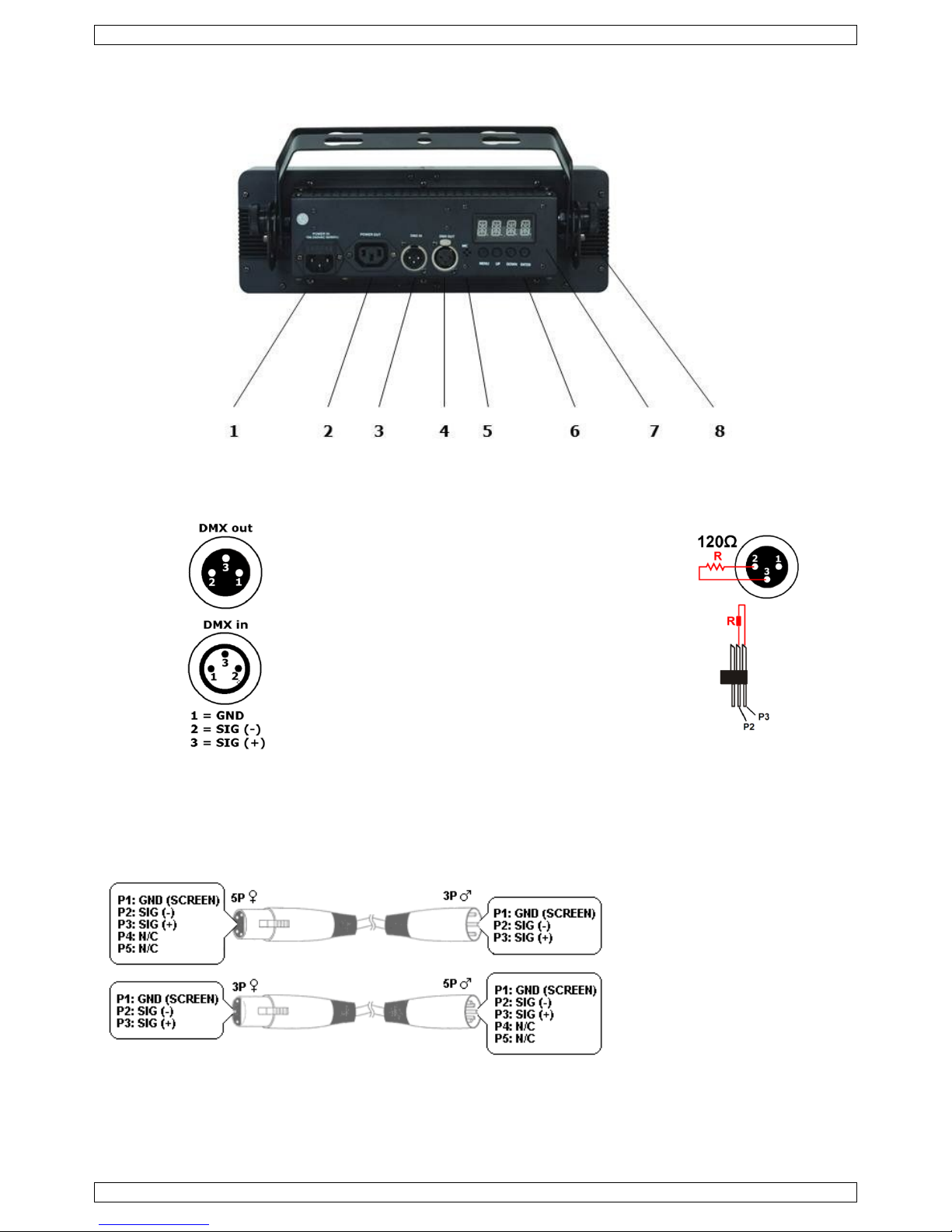
5. Overview
Refer to the illustrations on page 2 of this manual.
1
power input + fuse holder
5
built-in microphone
2
power output
6
control buttons
3
DMX input
7
display
4
DMX output
8
bracket
6. Installation
Choose a suitable mounting spot. Mount the device in the desired angle using the included bracket. Connect the
power cord to the mains. Disconnect after use.
Mounting the device
Have the device installed by a qualified person, respecting EN 60598-2-17 and all other applicable norms.
The carrying construction must be able to support 10 times the weight of the device for 1 hour without
deforming.
The installation must always be secured with a secondary attachment e.g. a safety cable.
Never stand directly below the device when it is being mounted, removed or serviced. Have a qualified
technician check the device once a year and once before you bring it into service.
Install the device in a location with few passers-by that is inaccessible to unauthorised persons.
Overhead mounting requires extensive experience: calculating workload limits, determining the installation
material to be used… Have the material and the device itself checked regularly. Do not attempt to install
the device yourself if you lack these qualifications as improper installation may result in injuries.
For truss mounting, use an appropriate clamp (not incl.) and fit an M10 bolt through the centre of the
(folded) bracket.
LX111
V. 02 – 28/03/2013 5 ©Velleman nv
Adjust the desired inclination angle via the mounting bracket and tighten the bracket screws.
Make sure there is no flammable material within a 0.5 m radius of the device.
Have a qualified electrician carry out the electric connection.
Connect the device to the mains with the power plug. All devices must be powered directly off a grounded
switched circuit and cannot be run off a rheostat or dimmer circuit, even if the rheostat or dimmer channel
is used solely for 0 % to 100 % switching.
The device has a power output to supply power to another device. When connecting several devices in a
daisy chain via this output, make sure that the total current does not exceed the power line’s nominal
current. Use power cables with an adequate section. If you do not use the power linking feature, be sure to
use the included screw-on cap to prevent any water from getting into the power cords.
The installation has to be approved by an expert before the device is taken into service.
DMX-512 Connection
When applicable, connect an XLR cable to the female XLR output of a controller (not incl.) and the other
side to the male XLR input of the device. Multiple devices can be linked through serial linking. The linking
cable should be a dual core, screened cable with XLR input and output connectors.
Maximum recommended serial data link distance is 500 meters (1640 ft). Maximum recommended number
of devices on a serial data link is 32 devices.
A DMX terminator is recommended for installations where the DMX cable has to run a long distance or is in
an electrically noisy environment (e.g. discos). The terminator prevents corruption of the digital control
signal by electrical noise. The DMX terminator is simply an XLR plug with a 120 Ω resistor between pins 2
and 3, which is then plugged into the XLR output socket of the last device in the chain.
7. Operation
The device can be used in the following modes:
stand-alone mode (with the built-in microphone)
stand-alone mode
sound-activated
stand-alone mode: automatic or sound-activated
master/slave
with a DMX512 controller.
7.1 Control Panel Navigation
Access the control panel functions using the four panel buttons located directly underneath the display. From
left to right:
Button
Function
<MENU>
used to access the menu or to return to a previous menu option
<UP>
scrolls through the menu options in ascending order
<DOWN>
scrolls through the menu options in descending order
<ENTER>
used to select and store the current menu or option within the menu
The control panel display shows the menu items you select from the menu map. When a menu function is
selected, the display will show immediately the first available option for the selected menu function. To
select a menu item, press <ENTER>.
Use the <UP> and <DOWN> buttons to navigate the menu map and menu options. Press <ENTER> to
access the menu function currently displayed or to enable a menu option. To return to the previous option
or menu without changing the value, press the <MENU> button.
The menu contains the following items:
Menu item
Description
3—CH
3 channel settings
5--CH
5 channel settings
9--CH
9 channel settings
10--CH
10 channel settings
13 --CH
13 channel settings
C--
Static colour show
LX111
V. 02 – 28/03/2013 6 ©Velleman nv
Menu item
Description
P--
Built-in programs
S--
Speed
Snd
Sound random program
Sens
Sound sensitivity
U--
User custom colours
dim
Dimmer speed setting
dim1: Dimmer speed fast
dim2 : Dimmer speed middle
dim3 : Dimmer speed slow
Send
Send data(linking fixture)
send1: Single fixture
send3 : 3 pcs linking
SlA
Slave mode(linking fixture)
SLA 1 : Program follows the master fixture
SLA 2 : Receive the second program data
SLA 3 : Receive the third program data
7.2 Master/Slave Mode
The master/slave mode allows connecting several devices to a single master device. All slave devices will then
work synchronously with the master device.
You need to set one device to master mode and all other devices to slave mode.
1. Connect all devices in series with DMX cables.
2. The first unit in the chain functions as the master device. Set up the unit as described above.
3. On each slave device, press <MENU> until <SLA> is displayed and press <ENTER>.
4. Use <UP> and <DOWN> to select an option and press <ENTER>.
7.3 DMX Mode
This mode allows you to control the device by any universal DMX controller.
All DMX-controlled devices need a digital start address so that the correct device responds to the signals.
This digital start address is the channel number from which the device starts to ―listen‖ to the DMX
controller. The same starting address can be used for a whole group of devices or an individual address can
be set for every device.
When all devices have the same address, all the units will ―listen‖ to the control signal on one particular
channel. In other words: changing the settings of one channel will affect all devices simultaneously. If you
set individual addresses, each device will ―listen‖ to a separate channel number. Changing the settings of
one channel will only affect the device in question.
To set the device to work with a DMX controller:
1. Press <MENU> to select a channel and press <ENTER>.
2. Use <UP> and <DOWN> to set the DMX starting address (A001-A512) and press <ENTER>.
Example:
To use the 1-channel mode, set the start address of the first unit to 1 (CH1), the second to 2 (CH2), the third
to 3 (CH3), and so on. The highest start address is 512.
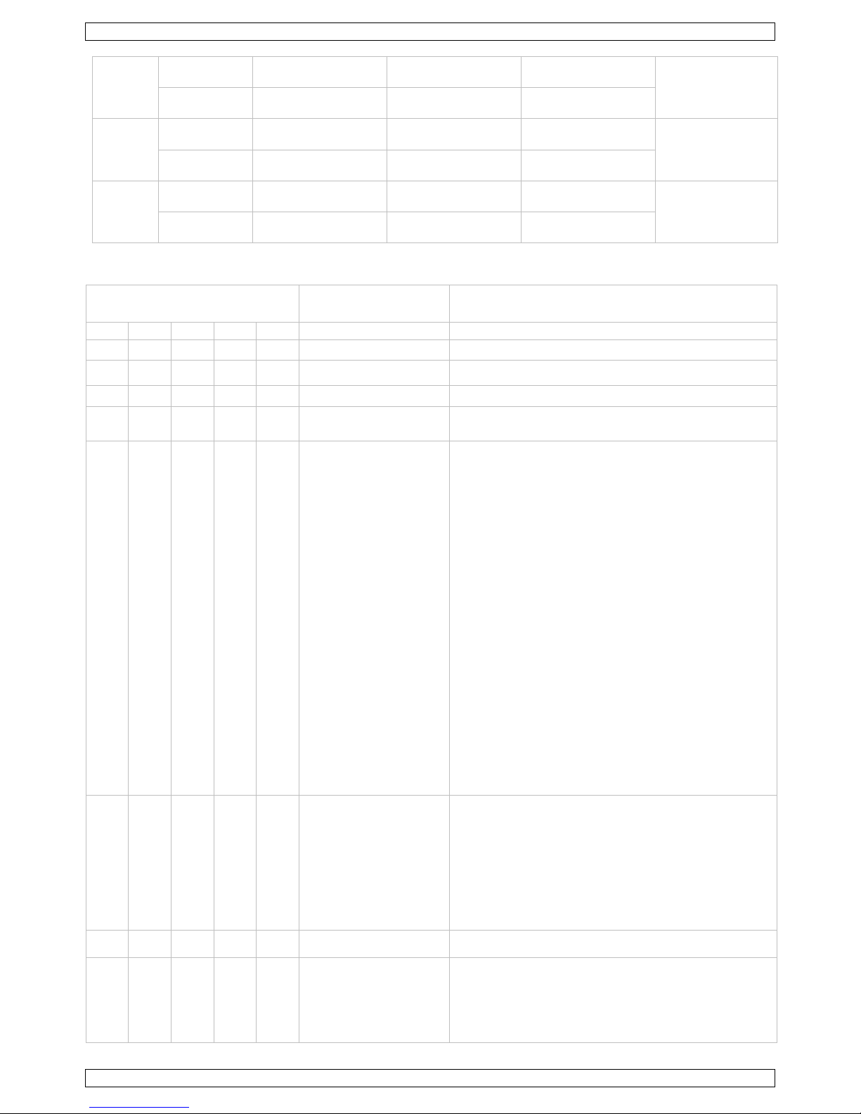
Use the table below to define the correct address. The table shows the settings for units 1 to 3. Apply the same
principle for all units and channels.
Channel mode
Start addresses
Highest start
address
First unit
Second unit
Third unit
3
Start address
1
4 (1 + 3)
7 (4 + 3)
510
Channel
1~3
4~6
7~9
5
Start address
1
6 (1 + 5)
11 (6 + 5)
508
Channel
1~5
6~10
11~15
LX111
V. 02 – 28/03/2013 7 ©Velleman nv
9
Start address
1
10 (1 + 9)
19 (10 + 9)
504
Channel
1~9
10~18
19~27
10
Start address
1
11 (1 + 10)
21 (11 + 10)
503
Channel
1~10
11~20
21~30
13
Start address
1
14 (1 + 13)
27 (14 + 13)
500
Channel
1~13
14~26
27~39
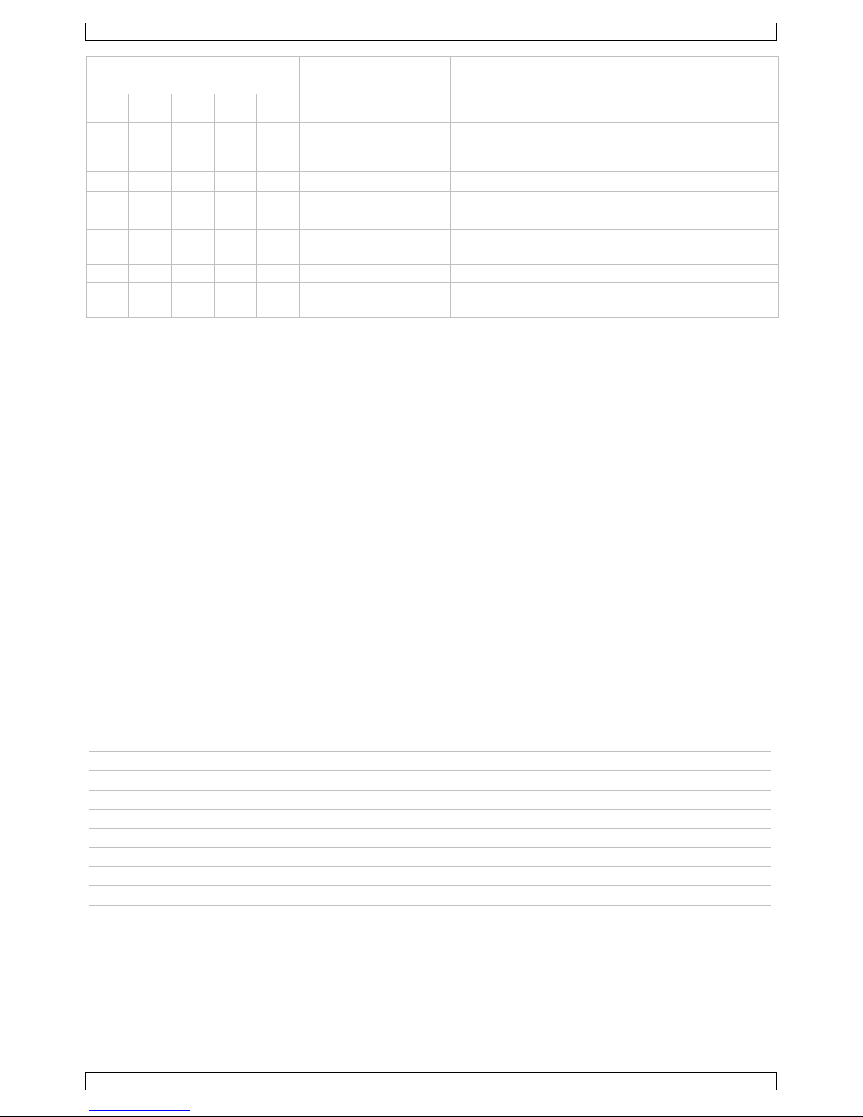
DMX Channel Values
Channel mode
3ch 5ch 9ch 10ch 13ch
Function
Settings
1 1 12
Dimmer
000-255
1 2 2
Red
000-255
2 3 3
Green
000-255
3 4 4
Blue
000-255
5 5 13
Shutter
000-010 No Function
011-255 Strobe Slow to Fast
6 Manual Colour + Colour
Temperature
000~010 No Function
011~030 R 100%, G 0~100%, B 0%
031~050 R 100%~0% G 100% B 0%
051~070 R 0% G 100% B 0~100%
071~090 R 0% G 100%~0% B 100%
091~110 R 0%~100% G 0% B 100%
111~130 R 100% G 0% B 100%~0%
131~150 R 100% G 0%~100% B 0%~100%
151~170 R 100%~0% G 100%~0% B 100%
171~200 R 100% G 100% B 100%
201~205 Colour temperature 1
206~210 Colour temperature 2
211-215 Colour temperature 3
216-220 Colour temperature 4
221-225 Colour temperature 5
226-230 Colour temperature 6
231-235 Colour temperature 7
236-240 Colour temperature 8
241-245 Colour temperature 9
246-250 Colour temperature 10
251-255 Colour temperature 11
7 10
Auto Programs
000-010 No Function
011-040 Chase 1
041-080 Chase 2
081-120 Chase 3
121-160 Chase4
161-200 Chase 5
201-240 Chase 6(run1~4Chase)
241-255 Sound
8 11
Auto Speed
000-255 Speed Slow to Fast
9
Dim Mode
000-051 Menu Setting dimmer mode
052-101 dimmer mode off
102-152 dimmer mode 1
153-203 dimmer mode 2
204-255 dimmer mode 3
LX111
V. 02 – 28/03/2013 8 ©Velleman nv
Channel mode
3ch 5ch 9ch 10ch 13ch
Function
Settings
10
NULL
1 1
Red 1
000-255
2 2
Green 1
000-255
3 3
Blue 1
000-255
4 4
Red 2
000-255
5 5
Green 2
000-255
6 6
Blue 2
000-255
7 7
Red 3
000-255
8 8
Green 3
000-255
9 9
Blue 3
000-255
8. Cleaning and Maintenance
All screws should be tightened and free of corrosion.
The housing, the lenses, the mounting supports and the installation location (e.g. ceiling, suspension,
trussing) should not be deformed, modified or tampered with; e.g. do not drill extra holes in mounting
supports, do not change the location of the connections…
Mechanically moving parts must not show any signs of wear and tear.
The electric power supply cables must not show any damage. Have a qualified technician maintain the
device.
Disconnect the device from the mains prior to maintenance activities. Let the device cool down.
Wipe the device regularly with a dry, lint-free cloth. Do not use alcohol or solvents.
Do not immerse the device in any liquid.
There are no user-serviceable parts.
There are no user-serviceable parts, apart from the fuse.
Contact your dealer for spare parts if necessary.
Replacing the fuse
Only replace the fuse by a fuse of the same type and rating.
1. Before replacing the fuse, unplug the mains lead.
2. Wedge the fuse holder out of its housing with a flat-head screwdriver.
3. Remove the damaged fuse from its holder and replace with the exact same type of fuse.
4. Insert the fuse holder back in its place and reconnect power.
9. Technical Specifications
power supply
100 ~ 240 VAC / 50 - 60 Hz
power consumption
45 W
LED source
3 high power tri-colour COB LEDs
beam angle
63°
pitch
115
DMX in- and output
3-pin XLR
dimensions
344 x 115 x 90 mm
weight
3.6 kg
Use this device with original accessories only. Velleman nv cannot be held responsible in the event
of damage or injury resulting from (incorrect) use of this device.
For more info concerning this product and the latest version of this manual, please visit our website
www.luxibel.com.
The information in this manual is subject to change without prior notice.

LX111
V. 02 – 28/03/2013 9 ©Velleman nv
© COPYRIGHT NOTICE
The copyright to this manual is owned by Velleman nv. All worldwide rights reserved. No part of this
manual may be copied, reproduced, translated or reduced to any electronic medium or otherwise without the
prior written consent of the copyright holder.
LX111
V. 02 – 28/03/2013 10 ©Velleman nv
GEBRUIKERSHANDLEIDING
1. Inleiding
Aan alle ingezetenen van de Europese Unie
Belangrijke milieu-informatie betreffende dit product
Dit symbool op het toestel of de verpakking geeft aan dat, als het na zijn levenscyclus wordt
weggeworpen, dit toestel schade kan toebrengen aan het milieu. Gooi dit toestel (en eventuele
batterijen) niet bij het gewone huishoudelijke afval; het moet bij een gespecialiseerd bedrijf
terechtkomen voor recyclage. U moet dit toestel naar uw verdeler of naar een lokaal recyclagepunt
brengen. Respecteer de plaatselijke milieuwetgeving.
Hebt u vragen, contacteer dan de plaatselijke autoriteiten betreffende de verwijdering.
Dank u voor uw aankoop®! Lees deze handleiding grondig voor u het toestel in gebruik neemt. Werd het toestel
beschadigd tijdens het transport, installeer het dan niet en raadpleeg uw dealer.
2. Veiligheidsinstructies
Wees voorzichtig bij de installatie: raak geen kabels aan die onder stroom staan om dodelijke
elektroshocks te vermijden.
Trek de stekker uit het stopcontact (trek niet aan de kabel!) voordat u het toestel reinigt en als
u het niet gebruikt. Neem de voedingskabel enkel vast bij de stekker, trek niet aan de kabel.
Gebruik het toestel enkel binnenshuis. Bescherm het toestel tegen regen, vochtigheid en
opspattende vloeistoffen. Plaats geen objecten gevuld met vloeistof op of naast het toestel.
Houd dit toestel buiten het bereik van kinderen en onbevoegden.
Opgelet: de behuizing wordt zeer warm tijdens gebruik.
Kijk niet rechtstreeks in de lichtbron, om het volgende te vermijden:
epilepsieaanvallen bij gevoelige personen
tijdelijke blindheid (flitsblindheid)
permanente en onherroepelijke schade aan de ogen.
Er zijn geen door de gebruiker vervangbare onderdelen in dit toestel. Voor onderhoud of
reserveonderdelen, contacteer uw dealer.
Dit toestel valt onder beschermingsklasse I. Het toestel moet dus geaard zijn. Een geschoolde technicus
moet de elektrische aansluiting verzorgen.
De beschikbare netspanning mag niet hoger zijn dan de spanning in de specificaties achteraan de
handleiding.
De voedingskabel mag niet beschadigd zijn of ingekort worden. Laat uw dealer zo nodig een nieuwe kabel
plaatsen.
Maak het toestel vast met een geschikte veiligheidskabel (bijv. VDLSC7N of VDLSC8N).
Installeer het toestel op een minimumafstand van 0.5 m van ontvlambare en explosieve voorwerpen of
stoffen.
Zorg voor een minimumafstand van 0,5 m tussen de lichtuitgang van het toestel en het belichte oppervlak.
De maximale omgevingstemperatuur bedraagt 40 °C. Gebruik het toestel niet bij hogere temperaturen.
3. Algemene richtlijnen
Raadpleeg de Velleman® service- en kwaliteitsgarantie achteraan deze handleiding.
Bescherm dit toestel tegen stof en extreme temperaturen. Zorg dat de verluchtingsopeningen
niet verstopt geraken. Voorzie een ruimte van minstens 1" (± 2,5 cm) tussen het toestel en elk
ander object.
Bescherm het toestel tegen schokken. Vermijd brute kracht tijdens de bediening van het
toestel.
LX111
V. 02 – 28/03/2013 11 ©Velleman nv
Leer eerst de functies van het toestel kennen voor u het gaat gebruiken. Ongeschoolde personen mogen dit
toestel niet gebruiken. Meestal is beschadiging het gevolg van onprofessioneel gebruik.
Om veiligheidsredenen mag u geen wijzigingen aanbrengen. Schade door wijzigingen die de gebruiker heeft
aangebracht aan het toestel valt niet onder de garantie.
Gebruik het toestel enkel waarvoor het gemaakt is. Andere toepassingen kunnen leiden tot kortsluitingen,
brandwonden, elektrische schokken, enz. Bij onoordeelkundig gebruik vervalt de garantie.
De garantie geldt niet voor schade door het negeren van bepaalde richtlijnen in deze handleiding en uw
dealer zal de verantwoordelijkheid afwijzen voor defecten of problemen die hier rechtstreeks verband mee
houden.
De leds en mechanische schade vallen niet onder de garantie.
Laat dit toestel installeren en onderhouden door een geschoolde technicus.
Om beschadiging te vermijden, zet u het toestel best niet aan onmiddellijk nadat het werd blootgesteld aan
temperatuurschommelingen. Om beschadiging te vermijden, moet u wachten tot het toestel
kamertemperatuur heeft bereikt.
Dit toestel is ontworpen voor professioneel gebruik op podia, in disco's, enz.
U mag het toestel alleen binnenshuis gebruiken.
Gebruik een geschikte voedingsbron (zie Technische specificaties hieronder).
Lichteffecten zijn niet ontworpen voor continue werking: regelmatige onderbrekingen doen ze langer
meegaan.
Gebruik de oorspronkelijke verpakking wanneer u het toestel vervoert.
Bewaar deze handleiding voor verdere raadpleging.
4. Eigenschappen
driekleurig, high-power LED-paneel voor betoverende 'wash', blinder- of andere effecten
elk led is instelbaar voor pixelmapping
DMX-gestuurd via 3, 5, 9, 10 of 13 kanalen
automatische programma's via de master/slave- of DMX-modus met instelbare snelheid
2 x 8-digit LCD-scherm voor een gemakkelijke menu-instelling
COB-led voor een hoogwaardige RGB-kleurenmenging
extra voedingsuitgang
beugel voor het aansluiten van meerdere toestellen, om een muur te vormen
robuuste beugel voor truss-ophanging
met Neutrik powerCON-ingang/uitgang
5. Omschrijving
Raadpleeg de afbeeldingen op pagina 2 van deze handleiding.
1
voedingsingang + zekering
5
ingebouwde microfoon
2
voedingsuitgang
6
bedieningstoetsen
3
DMX-ingang
7
display
4
DMX-uitgang
8
beugel
6. Installatie
Kies een geschikte montageplaats. Monteer het toestel in de gewenste hoek met de meegeleverde beugel.
Koppel de voedingskabel aan het lichtnet. Ontkoppel na gebruik.
Het toestel monteren
Laat een geschoolde technicus dit toestel installeren conform EN 60598-2-17 en andere toepasselijke
normen.
De constructie waaraan het toestel wordt bevestigd, moet gedurende 1 uur 10 x het gewicht van dit toestel
kunnen dragen zonder te vervormen.
Maak het toestel ook vast met een veiligheidskabel.
Sta nooit recht onder het toestel wanneer u het monteert, verwijdert of reinigt. Laat het toestel controleren
door een geschoolde technicus voor u het in gebruik neemt en laat het 1 x per jaar volledig nakijken.
Installeer dit toestel op een plaats waar weinig mensen voorbijkomen en die niet toegankelijk is voor
onbevoegden.
LX111
V. 02 – 28/03/2013 12 ©Velleman nv
Een degelijke praktijkervaring is vereist voor de plaatsing van dit toestel: u moet de maximumbelasting van
de draagconstructie kunnen berekenen, weten welk constructiemateriaal u kunt gebruiken... Laat het
materiaal en het toestel regelmatig nakijken. Monteer het toestel niet zelf indien u er geen ervaring mee
heeft. Een slechte montage kan leiden tot verwondingen.
Voor montage op een lichtbrug, gebruik een geschikte klem (niet meegelev.) en draai een M10-bout
doorheen het midden van de (geplooide) beugel.
Regel de gewenste invalshoek door middel van de montagebeugel en draai de regelschroeven stevig aan.
Verwijder alle brandbaar materiaal in een straal van 0,5 m rond het toestel.
Laat het toestel aansluiten door een geschoolde elektricien.
Sluit het toestel via de stekker aan op het lichtnet. Alle toestellen moeten via een geaard stopcontact
gevoed worden en mogen niet via een variabele weerstand of dimcircuit gevoed worden, ook al gebruikt u
de variabele weerstand of het dimcircuit als een 0% tot 100% inschakeling.
Het toestel heeft een voedingsuitgang waar een volgend toestel kan op aangesloten worden. Bij het
aansluiten van meerdere toestellen in een ketting via deze uitgang, mag de totale stroom de nominale
stroom van de stroomkring niet overschrijden. Gebruik voedingskabels met een geschikte diameter. Indien
u de voedingsuitgang niet gebruikt, dient u de meegeleverde schroefdop te gebruiken om het
binnendringen van water in de voedingskabels te voorkomen.
De installatie moet voor het eerste gebruik gekeurd worden door een expert.
DMX512-aansluiting
Indien van toepassing, sluit een XLR-kabel aan de vrouwelijke XLR-uitgang van een controller (niet
meegelev.) en het andere uiteinde van de mannelijke XLR-ingang van het toestel. U kunt meerdere
toestellen aan elkaar koppelen met behulp van een seriële koppeling. Gebruik daarvoor een 2-aderige
afgeschermde kabel met XLR ingang- en uitgangsaansluitingen.
De maximaal aanbevolen kabellengte is 500 meter. Het aanbevolen maximum aantal toestellen op
eenzelfde aansluiting is 32.
Een DMX-eindweerstand is aanbevolen als de DMX-kabel vrij lang is of wordt gebruikt in een omgeving met
veel elektrische ruis (bv. een discotheek). De eindweerstand voorkomt corruptie van het digitale
controlesignaal door elektrische ruis. De DMX-eindweerstand is niets meer dan een XLR-stekker met een
weerstand van 120 Ω van pin 2 naar 3. Deze XLR-stekker wordt dan aangesloten op de XLR-uitgang van
het laatste toestel in de reeks.
7. Gebruik
Het toestel kan in verschillende modi gebruikt worden:
autonome modus (met de ingebouwde microfoon)
autonome modus
muziekgestuurd
stand-alone-modus: automatisch of muziekgestuurd
master/slave-modus
met DMX512-sturing.
7.1 Het bedieningspaneel
Bedien het paneel met behulp van de vier knoppen onderaan de display. Van links naar rechts:
Knop
Functie
<MENU>
toegang tot het menu of terugkeer naar de vorige menuoptie
<UP>
scroll door de verschillende menuopties in stijgende volgorde
<DOWN>
scroll door de verschillende menuopties in dalende volgorde
<ENTER>
selectie en bevestiging van een optie
De geselecteerde menufunctie wordt op de display weergegeven. De display geeft de eerstvolgende
menuoptie onder de functie weer. Selecteer een menuoptie met <ENTER>.
Scroll doorheen het menu met <UP> en <DOWN>. Druk op <ENTER> om de weergegeven menufunctie te
selecteren of een optie te activeren. Druk op <MENU> om naar het hoofdmenu terug te keren zonder de
waarde te hebben gewijzigd.
Het menu bestaat uit de volgende items:
Menu-item
Beschrijving
3--CH
3-kanaalsinstellingen
 Loading...