

LuxHome USC423A User Manual
USC423A 868MHz GSM Alarm System
USC423A 868MHz GSM Alarm System
1
User Manual
1. Introduction
The USC423A GSM Alarm Panel is a control panel that is compatible with other
868MHz security devices from Everspring, such as wire free PIR Detectors, Remote
Controls and RFID tags.
Note: Due to frequency issues within the design of the USC423A GSM Alarm Control
panel. The USC423A GSM Alarm Control Panel is not compatible with Three Network
SIM Cards used in the UK.
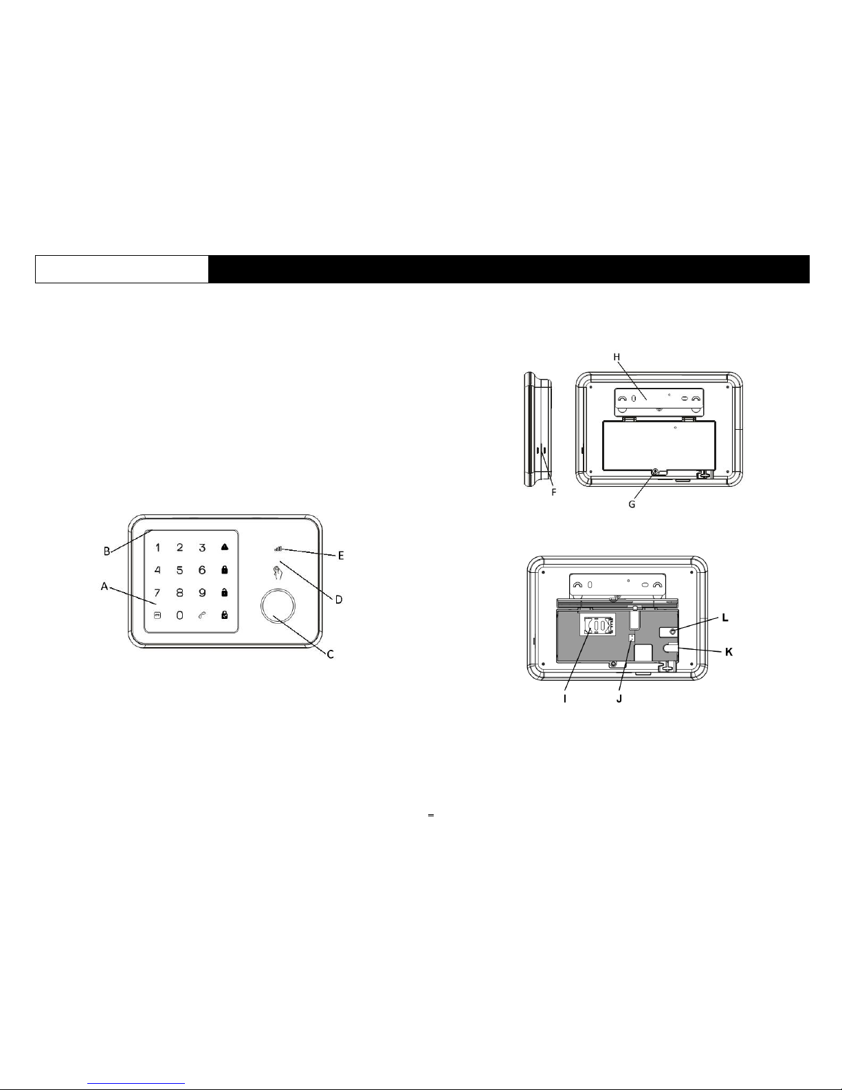
2. Product overview
A. Touch keypad D. RFID sensor area
B. Microphone E. GSM status led
C. Siren
F. Speaker G. Battery cover H. Wall mounting bracket
When battery cover is removed:
I. SIM card slot J. Battery connector
K. DC-jack L. Factory reset
USC423A 868MHz GSM Alarm System
USC423A 868MHz GSM Alarm System
2
3. Features
• 868MHz Radio Frequency
• 50 wireless zones
• SIM card slot for GSM connection
• SMS & phone call notifications up to 10 numbers
• Easy operation by App
• Easy disarm by RFID tag, with up to 50 tags supported.
• Dial and receive phone calls
• Hands-free two-way talking
• Siren Volume up to 95dB
• Notify user if door/window not closed when trying to Arm
• Hidden Duress Code capability
• Tamper protection feature
• RF jamming detection
4. Install SIM card and first set up
4-1 SIM card installation
Like all GSM devices the GSM alarm panel requires a SIM card to operate.
4-1-1 Preparing the SIM card
a. The SIM card needs to be unlocked before use. You can use a mobile phone to
cancel the input of PIN code or PUK code.
b. Ask your local carrier to disable voice message function of this SIM card.
c. As alarm messages and sending SMS require fees, please inquire with your local
carrier about their charging standards.
d. The SIM card size required is Mini SIM. For Micro SIM and Nano SIM, use a SIM
card adaptor before inserting into the alarm panel.
e. Ensure the SIM card has not expired.
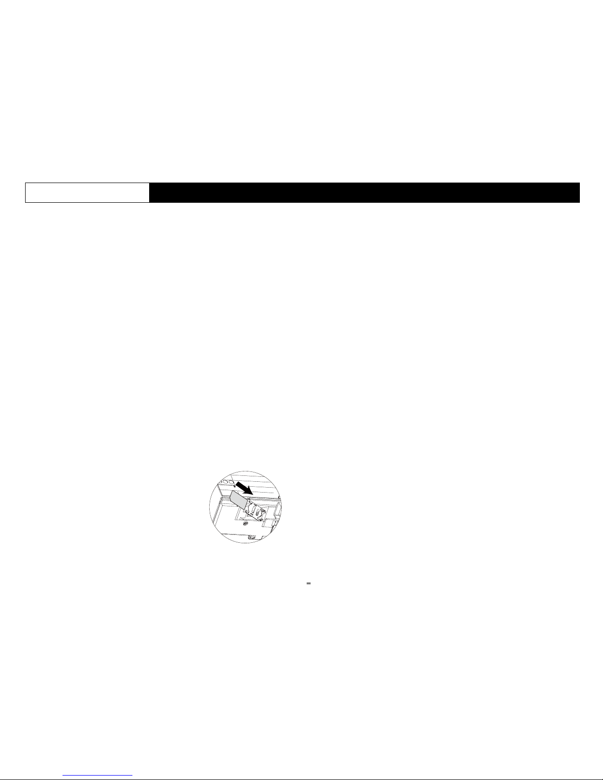
4-1-2 Inserting the SIM card
1. Remove battery cover of the alarm panel.
2. Insert a SIM card into the slot and connect the 9V
power adapter.
3. Wait until the GSM status led blinks slowly (once
every 3 seconds) indicating the SIM card is ready for
use.
4-2 Setting Up the Host Phone Number
First of all you need to enter the Host Phone Number so that the GSM notification
can function normally. The host phone number refers to the owner’s phone number
that needs to be entered into the alarm panel so that it will recognize SMS
commands sent from the owner’s phone.
Note: The “Show Caller ID” function on the owner’s mobile phone must be turned
on. The alarm panel can then determine if this number is authorized to use SMS
commands.
1. Begin configuration by entering the default configuration PIN code ‘1234’
2. On the touch keypad, enter 66 + PARTARM Key + Owner’s number +
PARTARM key
Note: Do not enter the phone number of the SIM card inside the alarm panel.
3. You will receive an SMS message saying phone number set successfully.
4. Your alarm panel can now be controlled from the smartphone app.
USC423A 868MHz GSM Alarm System
USC423A 868MHz GSM Alarm System
3
5. Definition of LEDs
LED Indication
GSM Status LED
Flashing once every second: Registering with host device
Flashing once every three seconds: Successf
ul registration
with GSM base station
Off: No AC power, alarm panel running on battery
[REC] LED & Key
Flashing: Recording / Listen-In in progress
On: Message playback in progress
[ARM] LED & Key
On: Arm Mode
Flashing: Arm Mode Exit Delay
[PARTARM] LED &
Key
On: Partial Arm Mode
Flashing: Partial Arm Exit Delay
[DISARM] LED &
Key
On: Disarm Mode
Flashing: Waiting for device binding / Test Mode
[ALARM] LED
Flashing: Alarm event triggered
[TEL] LED & Key
On: Using GSM Telephone
Flashing: GSM sending SMS
[RFID] LED
[LEDs around siren
area]
On: Reading Tag ID
Numbers 1-9
LED & Keys
On: Indicator for Detector zone 1 to 9, or which remote
keyfob 1- 9, or RFID tags 1-4
Number 0
LED & Key
On: Indicator for Detector zone > 9 or RFID tags > 4.
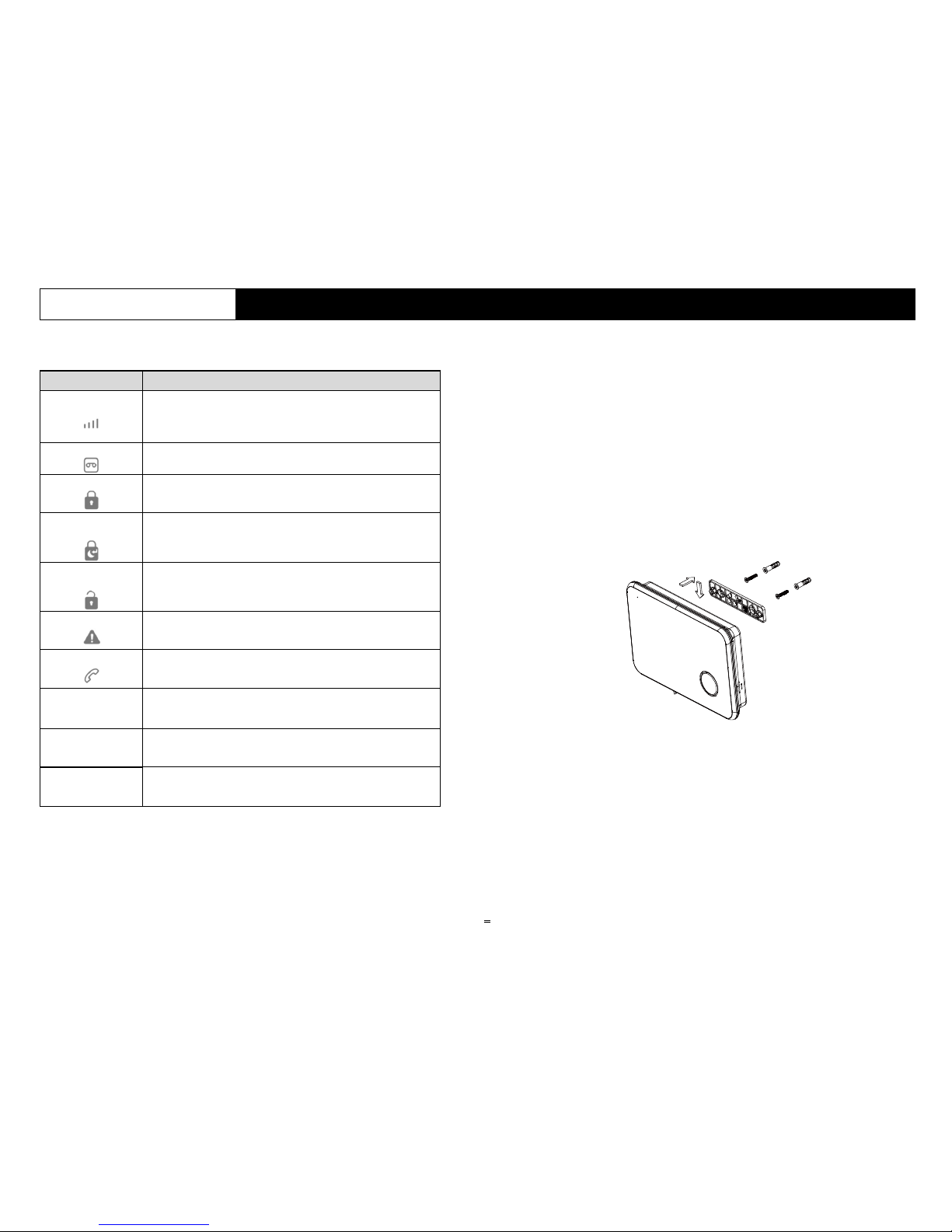
6. Mounting the Alarm Panel
Selecting a suitable location:
Mounted the alarm panel close to the door which you normally use to enter/exit
your building.
Note that the Alarm panel requires a power outlet to function.
Ensure the location selected has a good GSM signal. You can do this by cross
checking the signal bar on your phone at that location.
The panel must not be co-located or operated in conjunction with any other
nearby transmitter or antenna.
1. Remove the back panel mounting bracket of the GSM and mount the bracket on
the wall using wall anchors and screws.
2. Once secured, ensure the power connectivity and reattach the alarm panel to the
secured mounting bracket.
3. Power on the panel and test to make sure the GSM has good signal. Please see
Test Mode Point 4.

USC423A 868MHz GSM Alarm System
USC423A 868MHz GSM Alarm System
4
7. Configure the Alarm panel
There are 3 ways to configure the Alarm panel’;
1. Keypad: Basic and advanced settings can be configured through the touch
keypad. Whenever a key is pressed, the LED will light up and a key tone will
sound (when Key Tone is enabled).
Refer to Appendix A for the full list of keypad and button combination to various
settings. A 4-digit PIN code needs to be entered; the default PIN is ‘1234’.
2. SMS: Some settings can be configured remotely using predefined SMS text sent
from the owner’s phone. Refer to Appendix B for the list of SMS settings.
3. Smartphone App: The preferred method is by Android/IOS app available on
Google Play and Apple iTunes store. The App performs the same commands for
SMS settings listed in Appendix B.
7-1 Record and Playback Alarm Message
To start, a message needs to be recorded and stored in the system. This message
will be played back over the phone when the alarm is triggered.
Record alarm message
1. Enter the PIN + DISARM Key to disarm the system.
2. Enter PIN + REC button
3. When the REC LED flashes, say a brief messages into the microphone. The
maximum message length is 10 seconds.
4. Press PARTARM key to stop recording if message is shorter than 10 seconds
5. To playback the message, press and hold the REC button.
7-2 Notification Contacts
Create the list of contacts to call when an alarm event occurs.
Refer to Appendix B in the Alarm Voicecall Phone number list to set this up by
SMS or App.
Also create a list of contacts to send SMS messages when an alarm event occurs.
Refer to Appendix B for Alarm SMS Phone number list to set this up by SMS or
App.
Note:
a. The Host Phone Number will automatically appear as the first number in the list of
Alarm Voicecall number, Alarm SMS Phone number and Speed Dial No. in
Appendix B.
b. The “Show Caller ID” function on the contact’s mobile phone must be turned on to
send SMS commands. The alarm panel can then determine if this an authorized
number
7-3 Alarm Type
There are two alarm types,
- Alarm Type 1: loud siren with GSM voice call and SMS message. This is
intended to frighten away the intruder.
- Alarm Type 2: siren off but with GSM voice call and SMS message. This leaves
the intruder unaware the alarm has been triggered.
Refer to Appendix A to set up Alarm Type 1 or 2 using keypad.
7-4 Duress Disarm PIN code
Duress PIN code is your normal PIN code + 1.
For example: normal PIN code 1230 will have a duress PIN code of 1231
Normal PIN code of 9999 will have a duress PIN code of 0000.
An SMS will be sent to the Host Phone Number when using a duress PIN code to
disarm.
7-5 Test Mode
This is used to test the various functions after the alarm panel and Detectors have
been completely set up.
1. Enter the PIN + DISARM Key to disarm the system.
2. Enter the PIN + 03 to enter Test Mode. The DISARM LED will flash during Test
mode.
3. Time out for Test mode is 10 minutes, after which the system will return to disarm
mode. Press the DISARM Key if you wish to exit Test Mode at anytime.
Device test
4. If a Detector signal is received in Test Mode the chime will sound and keypad
LED will turn on to indicate which Detector (LED 1 – 9 indicates Detector Zone 1 –
9, Remote 1 – 9, or Tag 1 – 9. Other indications would be LED 0.
If the device is a Detector, the Detector Type will be indicated as below:
- Arm LED on: indicates the Detector will only trigger when Fully Armed
- Partial LED on: indicates the Detector will trigger when Fully Armed or Partial
Armed.
- Alarm LED on: indicates the Detector will trigger an immediate alarm (24 hours)
when Fully Armed / Partial Armed / Disarmed.

USC423A 868MHz GSM Alarm System
USC423A 868MHz GSM Alarm System
5
GSM signal test
5. Press and hold 7 for 3 or more seconds during Test Mode to display the GSM
signal strength indicated as:
- LED 1 :Good, LED 2: Normal, LED 3: Poor,
- ALARM LED : No Signal / SIM card registration failure / No SIM card
Siren enable/disable
6. Press and hold 8 for 3 or more seconds during Test Mode will send a System On /
Off command to the Wireless Siren.
SMS test
7. Press and hold 9 for 3 or more seconds during Test Mode will send a test SMS
message (including the current Alarm Mode, Delay Time, Siren On/Off, and Alarm
Time) to the Host Phone number.
7-6 Changing the PIN code
For security reasons it is strongly advised to change the default PIN code to a 4-digit
number of your choice. This prevents unauthorized access of your alarm panel from
its keypad.
Enter Old PIN (1234) + 06 +New PIN. The new PIN code will take effect immediately.
8. Arming /Disarming the Alarm Panel
8-1 Fully Arm Mode
1. Enter PIN + Arm Key. A long beep will sound if the PIN code is correct. Three
beeps will sound if the PIN code is incorrect.
2. If the PIN code is correct, the system will enter the Exit Delay countdown. The
ARM LED will flash and beep tone will sound once every second.
3. When the countdown reaches 5 second, the beep tone will sound twice every
second.
4. After the countdown is complete the system will enter Arm Mode. The Arm LED
will turn on.
8-2 Disarm Mode
1. Enter the PIN + DISARM Key. A long beep will sound if the PIN code is correct.
Three beeps will sound if the PIN code is incorrect.
2. If the PIN code is correct, the system will enter Disarm Mode immediately.
Note:
a. Remote keyfobs, Wireless Keypad, and SMS/App can be used to operate Arm /
Partial Arm / Disarm the system.
b. RFID Tags can be used to Disarm only. Simply swipe the tag in the area above
the siren on the alarm panel. An SMS will be sent to the Host Phone Number if
disarmed by RFID Tag. The SMS content can be modified for Tags 1-4 (e.g. “Jack
came home”, “Daniel disarmed”). SMS content for Tags 5-50 cannot be modified.
c. Contacts listed in Alarm SMS Phone number list can Arm, Partial Arm and
Disarm by SMS or App
8-3 Partial Arm Mode
1. Enter the PIN + PARTARM Key. A long beep will sound if the PIN code is correct.
Three beeps will sound if the PIN code is incorrect.
2. If the PIN code is correct, the system will enter the Exit Delay countdown. The
PARTARM LED will flash and beep tone will sound once every second.
3. When the countdown reaches 5 seconds, the beep tone will sound twice every
second.
4. After the countdown is complete the system will enter Partial Arm Mode. The
PARTARM LED will turn on.
.8-4 One Key Alarm Mode
The alarm panel provides an easy one key step to set Arm and Partial Arm mode:
From Disarm Mode:
- Press and hold ARM Key for 3 or more seconds to enter Fully Arm Mode;
- Press and hold PARTARM Key for 3 or more seconds to enter Partial Arm
Mode.
8-5 Open Door / Window Alert:
This feature checks if a door or window is left open when trying to Arm or Partial Arm
the system.
1. To turn on this feature, enter PIN + 08 + 1 + PARTARM
2. If a door/window Detector reports an open condition then the alarm panel will
beep for 10 seconds, and the keypad LED will indicate which Detector zone
number 1 – 9 (0 for other Detector Zones).
3. After the alert has ended it will enter the configured alarm mode. If all
doors/windows are closed the alert sounds will turn off.
You may also do a quick check while in Disarm mode:
- Pressing the ARM Key will check all doors and windows under Fully Arm and
display Detector number LED of opened doors or windows for 3 seconds.
- Pressing the PARTARM Key will check all doors and windows under Partial Arm
and display LED opened doors or windows for 3 seconds.
 Loading...