

LuxHome LHK110EK, LHK110EE Instruction Manual
LHK110EK/LHK110EE
2.4GHz Smart Home Security System
with 7-inch Touch Control Panel
Instruction Guide
* This product belongs to part of a security system that monitors/operates 24 hours nonstop.
** The contents in this manual are subject to modications without notice.
- 2 -
Safety Notice
1. Do not drop, puncture or disassemble the panel or camera; otherwise the warranty will be
voided.
2. Avoid all contact with water, and dry hands before using.
3. Never tug on the power cords. Use the plug to unplug it from the wall outlet.
4. Do not expose the panel or accessory camera to high temperature or leave it in direct
sunlight. Doing so may damage the device or cause the device to malfunction.
5. Use the device with care. Avoid harsh impact on the device.
6. For your own safety, avoid using the accessory camera or power off the camera when there is
a storm or lightning.
7. The panel is for indoor use. Do not expose the panel to outdoor harsh weather.
8. Use only the accessories and power adapters supplied by the manufacturer.
9. To meet the regulations pertaining to parental responsibility, keep the device out of the reach
of infants.
FCC/CE Warning
This equipment has been tested and found to comply with limits for a Class B
digital device, pursuant to Part 15 of the FCC rules and ETSI (EN) 300 440.
These limits are designed to provide reasonable protection against harmful
interference in residential installations. This equipment generates, uses, and
can radiate radio frequency energy, and if not installed and used in accordance with the instructions, may
cause harmful interference to radio communications.
However, there is no guarantee that interference will not occur in a particular installation. If this equipment
does cause interference to radio or television equipment reception, which can be determined by turning
the equipment off and on, the user is encouraged to try to correct the interference by one or more of the
following measures:
- Reorient or relocate the receiving antenna.
- Move the equipment away from the receiver.
- Plug the equipment into an outlet on a circuit different from that to which the receiver is connected.
- Consult the dealer or an experienced radio/television technician for additional suggestions.
You are cautioned that any change or modications to the equipment not expressly approved by the party
responsible for compliance could void your authority to operate such equipment.
Disposal
If the camera system no longer functions or can no longer be repaired, it must be disposed of according to
the valid statutory regulations. Disposal of spent batteries/accumulators:
You are required by law (Battery Ordinance) to return all spent batteries and accumulators. Disposing of
spent batteries/accumulators with common household waste is prohibited! Batteries/accumulators that
contain hazardous substances are marked with the symbols on the side. These symbols indicate that it is
prohibited to dispose of these batteries/accumulators in the household waste.
The abbreviations for the respective heavy metals are Cd = cadmium, Hg = mercury,
Pb = lead. You can return spent batteries/accumulators that can no longer be charged
to the designated collection points in your community, outlets or wherever batteries
or accumulators are sold. Following these instructions will allow you to fulll the legal
requirements and contribute to the protection of our environment!

- 3 -
Lithium-Polymer Battery Warning
1. This equipment contains a rechargeable lithium-polymer battery.
2. Do not charge the battery in temperatures below 0° C (32° F) or higher than 45° C (113° F).
3. Do not open or disassemble the battery.
4. The rechargeable batteries contained in this equipment may explode if put in or near a re.
5. Do not short-circuit the battery.
6. Do not charge the rechargeable battery pack used in this equipment with any charger other
than the one designed to charge this battery pack as specied in the owner’s manual. Using
another charger may damage the battery pack or cause the battery pack to explode.
CAUTION! Rechargeable Batteries Must Be Recycled or Disposed of Properly.
Device ID
System “Device ID” is provided on a label located on the back of the unit. The “Device ID” is
needed for remote viewing and control. For security purpose, it is recommenced for user to
copy the “Device ID” information to the user manual (in the blank below), followed by removing
the label containing the information of “Device ID”. Please store this manual in a safe place to
protect the device ID information for future reference.
Device ID:
Local Regulations
Always use discretion when installing CCTV surveillance equipment especially when there is
perceived policy. Enquire regarding local regulations applicable to the lawful installation of video
recording/surveillance. Third party consent may be required.
Requirements for Remote View
Supported Device
- iPhone / iPad with iOS 5.0 or later
- Android smartphone / tablet V4.0 or later
Note:
1) Not suitable for Windows or Blackberry Smartphones
2) Up to 6 remote connections are allowed at the same time
Recommended internet upload speed
512Kbps upload speed (or bandwidth) to achieve up to an average of 2FPS viewing speed.
2Mbps or more is recommended to achieve better frame rates on a smartphone’s live view.
Average viewing speed will depend on other restrictions by your ISP (internet service providers).

- 4 -
Introduction 5
Package Contents 6
Product Overview 6
Getting Started 7
Screen Display and Indicators 9
Operations Layer Diagram 11
Operation - Cameras 12
Replay 12
Record All 13
Schedule 13
Operation - Lights 14
Controlling the Lights 14
Operation - Alarms 15
Setting Alarm Mode 15
Viewing Logs 16
Setting - Cameras 17
Setting - Lighting Fixtures 18
Setting - Alarms 19
Setting - Network 20
Internet Setup 20
Security Code 20
Network Information 20
Email Alert 20
Setting - Advanced Options 21
Using APP on a Mobile Device 23
Downloading the APP 23
Launching the APP 23
Adding a New Panel 23
Registration 23
Main Functions Display 24
Live Camera View 24
Playback 25
Setting Alarm Mode
and Viewing Eventlog 26
Setting Lighting Fixtures 27
System Info 28
Specications 29
FAQ 30
List of Compatible Devices 30
Appendix A -
Arm Mode Flowchart 31
Appendix B -
Silent Arm Mode Flowchart 31
Appendix C -
Panic&Tamper Mode Flowchart 32
Appendix D -
Disarm Mode Flowchart 32
Table of Contents

- 5 -
Introduction
The touch control panel is designed to be the security center of your home. The system consists
of a touch screen control for system operation, cameras that monitor the surroundings of your
residence, various wireless sensors that provide perimeter and interior intruder protection, and
lighting xtures.
The system provides protection at home in three areas as depicted below:
OUTDOOR ZONE
Front door
INDOOR ZONE
W
PERSONAL
ZONE
W
indow
W
W
indow
Back door
Device classication:
Outdoor Zone: Lighting Cam
Indoor Zone : Motion sensor,
Door/Window contact detector
Personal Zone: Keyfob Panic
button
After setting the panel to be connected with cameras and alarms, you can arm or disarm the
system and view live camera images on this panel. The panel can also link up with smart plugs
and lighting xtures for wireless control of the lighting of your residence.
When a trigger event occurs, the system emits an alarm sound and can also inform the user via
email alert or smart phone APP notication. Lighting xtures may also be congured to light up to
attract attention. Video images from the cameras are simultaneously streamed and recorded in
the touch panel’s memory card for 2 minutes and can be played back for evidence.
Through the Smartphone APP users may view live video of the camera, set the system to Arm/
Disarm, turn on/off lighting xtures, activate recording at will and playback recorded video les.
The followings are some features of the panel:
• Can connect up to 4 wireless cameras and record live images by A/V signal streaming
• Supports up to 8 alarm devices connection
• Supports up to 8 lighting xtures/plugs connection and up to 5 pieces of lamps can be
congured to light up when alarm is triggered.
• Wireless connection and control of cameras/alarms/lighting xtures
• Supports up to 32GB micro SD card (4GB card included)
• Battery included (can be recharged and powered using AC adapter)
• Built-in speaker
- 6 -
Package Contents
• 2.4GHz 7” Touch Control Panel x1
• 2.4GHz Lighting Camera x1
• Wire Free PIR Motion Sensor x1
• Wire Free Magnetic Contact x1
• Wire Free Remote Control x1
• Plug Through Receiver x1
• 4GB micro SD card x 1
• Instruction Guide x1
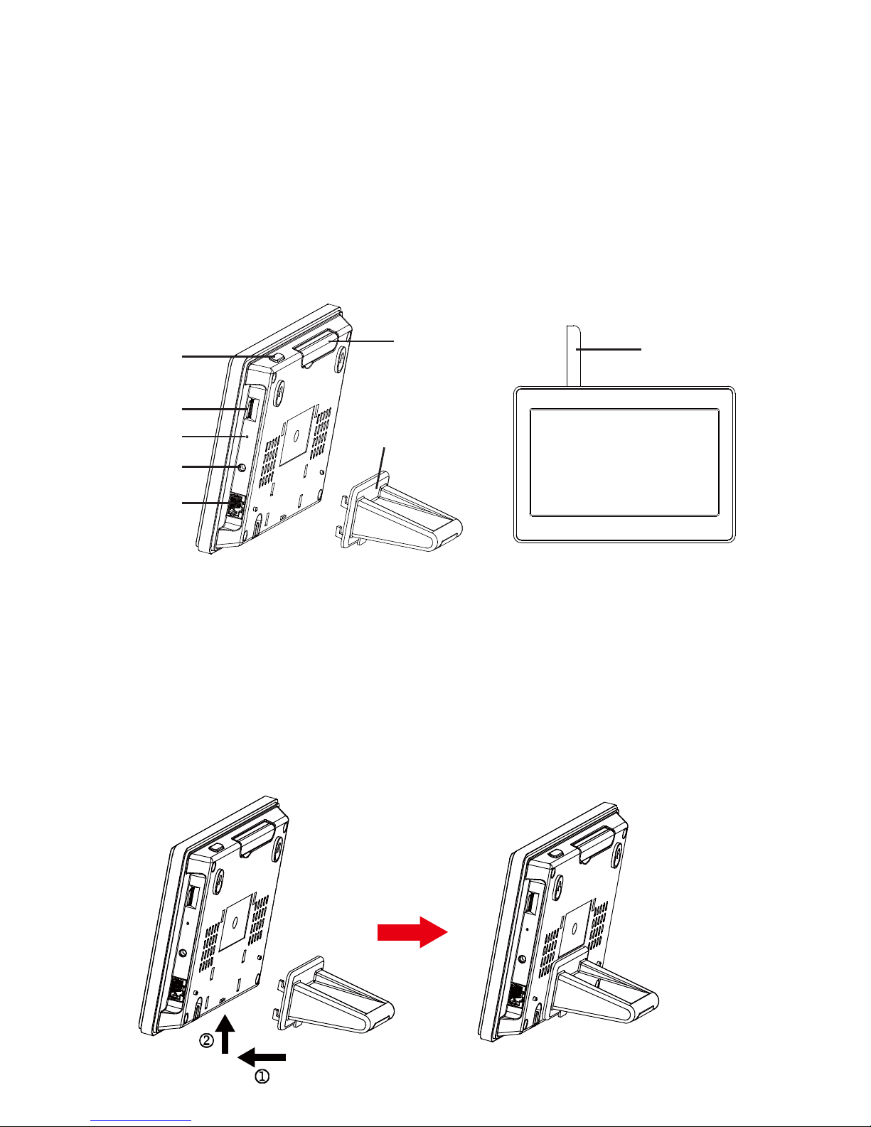
Product Overview
Antenna
LCD Touch
Screen
Antenna
Power Button*
Micro SD
Card Slot
Reset
DC Power in
Network Cable
Connection
Stand
* To power on/off the panel, press and hold down the power button for 3 seconds. After the panel is
powered on, pressing the button shortly can put the unit into sleep mode. To awake the panel from
sleep status, press the button once shortly.
The stand comes with the panel as a support when you need to place the panel on a at surface
(such as on a table). To set up the stand, follow the steps below:
1. Align the 4 hooks of the stand with the grooves on the back of the panel.
2. Place the hooks into the grooves and then slide the stand upward.
3. When the stand clicks into the housing, the setup is complete.
- 7 -
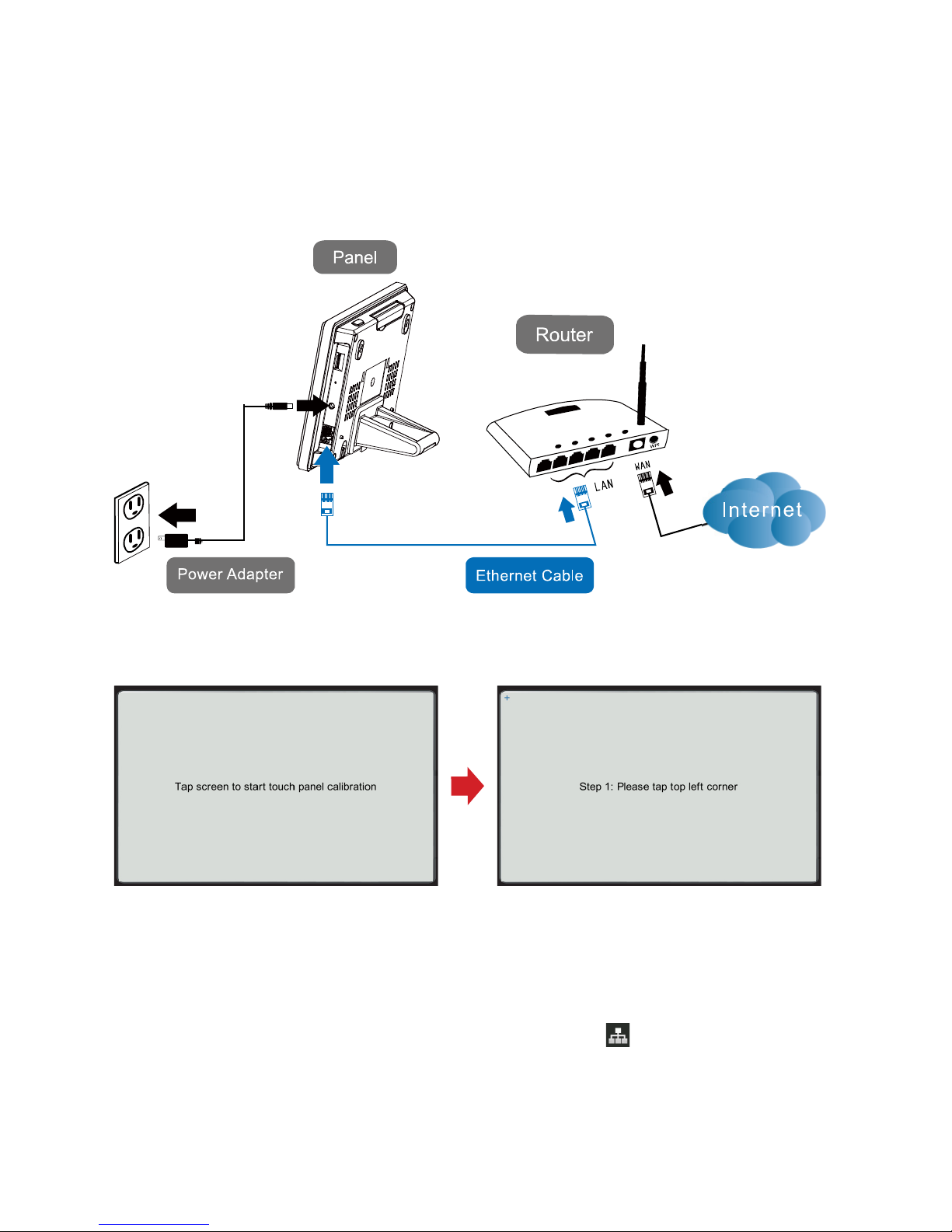
Getting Started
Unpack the kit contents and follow the steps below to set up your panel:
1. Connect the AC adapter’s connector to the panel and the adapter plug to a wall outlet.
2. Connect the RJ45 connector to the panel and the other end of the network cable to a “LAN”
port of your router. The router should have “DHCP” function enabled.
3. Power on the panel by pressing and holding the power button of the panel for about 3
seconds. Follow the on-screen instructions to complete the screen calibration.
4. Insert a micro SD card (4GB card included) into the card slot. You can use your own
micro SD card (max. 32GB). Format the card by tapping “Setting” “Advance” “Format
Storage”.
5. After the panel is powered on and connected to the network, the panel should have internet
connection within 2 minutes. The network connection icon ( ) should appear. The
recommended network setting is “DHCP” which is also the factory default. If you need to
congure the network settings manually, tap on “Setting” “Network” “Internet Setup”
“Static IP”.

- 8 -
6. Pairing with the accessory lighting camera:
1) Tap on the “Setting” button on the function bar to enter the camera setting screen.
2) Select the “Light Cam” icon on the left side and highlight an available slot on the right side
of the screen. Then tap on the “Pair” button.
3) Press the PAIR/ Button on the camera to do ID code learning with the panel.
4) Once the pairing is complete, the panel is able to display live camera images on the
screen. Refer to page 17 for detailed camera settings.
7. Adding the accessory alarm devices:
1) Tap on “Setting” “Alarm“ to enter the alarm setting screen.
2) There should be one PIR detector, one magnetic contact detector, and one remote control
in your package. These devices should do the code learning one at a time.
3) Select the “PIR” icon on the left side and highlight an available slot on the right side of the
screen. Then tap on the “Add” button.
4) Press the Learning Button (or Tamper Switch) on the PIR detector to do ID code learning
with the panel.
5) Once the learning is complete, repeat step 3 and 4 to set up the contact detector and
the remote control. Ensure to select a proper icon that corresponds with the to-be-added
device. Refer to page 19 for detailed alarm devices settings.
8. Adding the accessory wireless on/off plug:
1) Tap on “Setting” “Light“ to enter the lighting xture setting screen.
2) Press the Learning Button on the wireless plug to enter code learning mode.
3) Select the “On/Off Plug” icon on the left side and highlight an available slot on the right
side of the screen. Then tap on the “Add” button.
4) Once the learning is complete, the panel is able to control the on/off plug wirelessly.
Refer to page 18 for detailed lighting xtures settings.
9. Install the panel and accessory devices to appropriate locations. Note the accessory
devices should be located within the RF transmission range of the panel.
10. The default system security code is “123456”. You should change the security code
immediately to fortify protection. Tap on “Setting” “Network” “Security Code” to change
the code. Ensure to jot down your new code and store the password card in a safe place.
11. For security purpose, you are recommended to set up the email alert contact and APP
connection for push notifications. Tap on “Setting” “Network” “Email Alert” and use
“System Default” or “User Settings” item to set up the email alert contact. For APP setup,
refer to page 23 for detailed instructions.
Note: Step 6, 7, and/or 8 can be skipped if the accessory devices are pre-learned with the
control panel before shipping. Devices that are already paired with the panel will have a “Pre-
learned” sticker on each unit’s body, so you are able to identify which devices can work with the
panel right away.
*
*
*

- 9 -
Screen Display and Indicators
Press and hold the power button for 3 seconds to power on the panel and enter the main display.
Normal view:
: Battery power indicator
: Micro SD card capacity indicator. The used percentage of storage is displayed.
: Network status indicator. When the panel is connected to Local Area Network (LAN),
the icon will appear. When the panel is linked and open to the Internet, the
icon will switch to , which is also the only condition that someone in a remote
location can access the system via “LuxHome Guard” - the smartphone APP. Note
that whenever someone is operating the panel, the icon will switch to and any
attempt of remote access will be denied. This is to ensure the top priority of domestic
operation. The panel will switch to status after a short period of idling (provided
the panel is connected to Internet).
: Quad view & trigger indicator. Tap to enter cameras quad view. White icon means
no trigger. If a trigger has occurred, a red icon will display. If a trigger event
is happening, the red icon will ash, and you can tap the icon to enable all
cameras to start recording.
Note: When the panel is in camera live view, camera scanning, or video replaying,
the connected camera(s) will not automatically record videos upon triggered event.
However, within 10 seconds of trigger, you can tap on the ashing icon to start
recording.
: Tap to set Arm/Disarm/Silent Arm
- 10 -
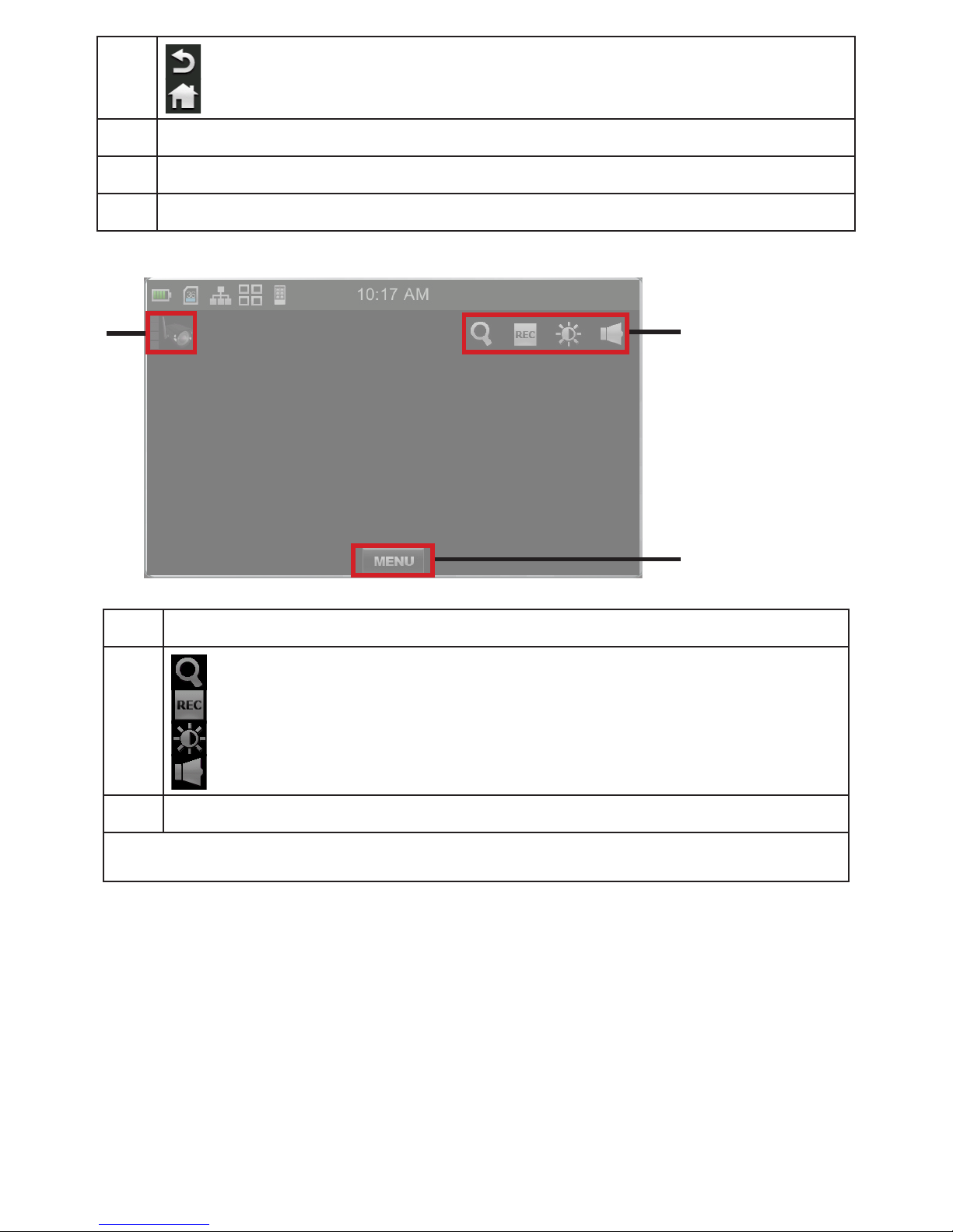
: Tap to go back to previous display
: Tap to go back to home display
Message bar
Main operation area
Group operation buttons
Camera view:
Active camera/Signal strength indicator
: Tap to digitally magnify the screen
: Toggle recording on/off
: Tap to adjust screen brightness
: Tap to adjust sound volume
Tap the MENU button to return to camera operation page
Note: In the camera live view, the lighting camera will turn on its light for better viewing if the
environment is too dark.
 Loading...