

LuxHome LHK100SU Instruction Manual
Wire Free
Alarm System
LHK100SU
Instruction Guide
For a Control Panel operated system please refer to the Operating
and Installation Instructions supplied with the Control Panel

2
Table of Contents
Kit Contents 3
Introduction and Overview 4
System Arming 4
Entry / Exit Delay 4
Alarm Lockout 4
Tamper Protection 4
Jamming Detection 4
Battery Monitoring 5
System House Code 5
Planning and Extending
your Wire Free Alarm System 6
Remote Control Unit 7
Setting the Remote Control 7
Testing the Remote Control 7
Passive Infrared (PIR)
Movement Detectors 8
Positioning the PIR Detector 8
Installing and Configuring
the PIR Movement Detector 9
Setting the PIR Detector 10
Testing The PIR Detector 11
Magnetic Contact Detectors 12
Positioning the
Magnetic Contact Detector 12
Installing and Configuring
the Magnetic Contact Detector 12
Setting the
Magnetic Contact Detector 13
Testing the
Magnetic Contact Detector 14
External Solar Siren 15
Choosing a Location for
the Solar Siren 15
Installing the Solar Siren 16
Setting the Solar Siren 16
Initial Power-Up of the Solar Siren 17
Siren Service Mode 18
Siren Operating Mode 18
Testing the System 19
Testing an Installed System 19
Operating Instructions 21
Arming the System 21
Disarming the System 22
Personal Attack (PA) Alarm 22
Device Tamper 22
Battery Monitoring 22
Maintenance 23
Solar Siren 23
Detectors and Remote Control 23
Batteries 23
Disposal and Recycling 24
Alarm Record 25
Troubleshooting 26
Extending your Alarm System 28
Accessories 28
Component Specification 29
3
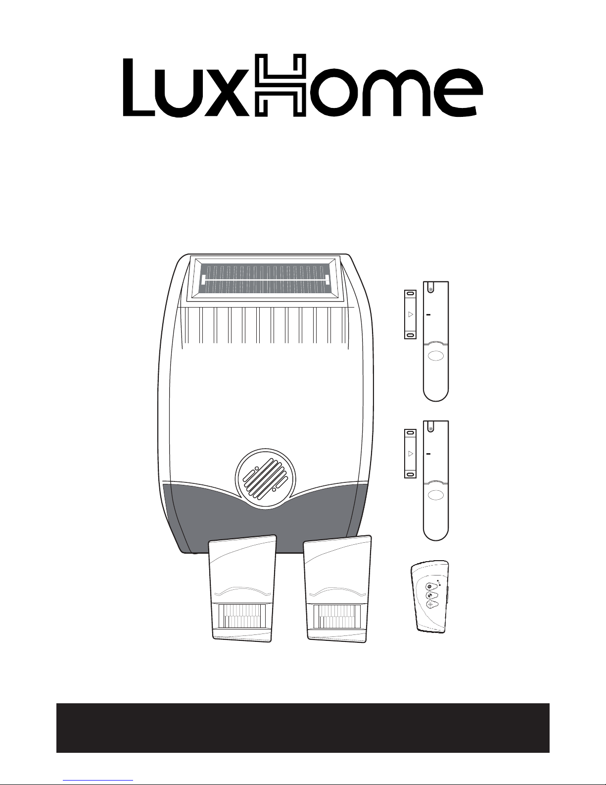
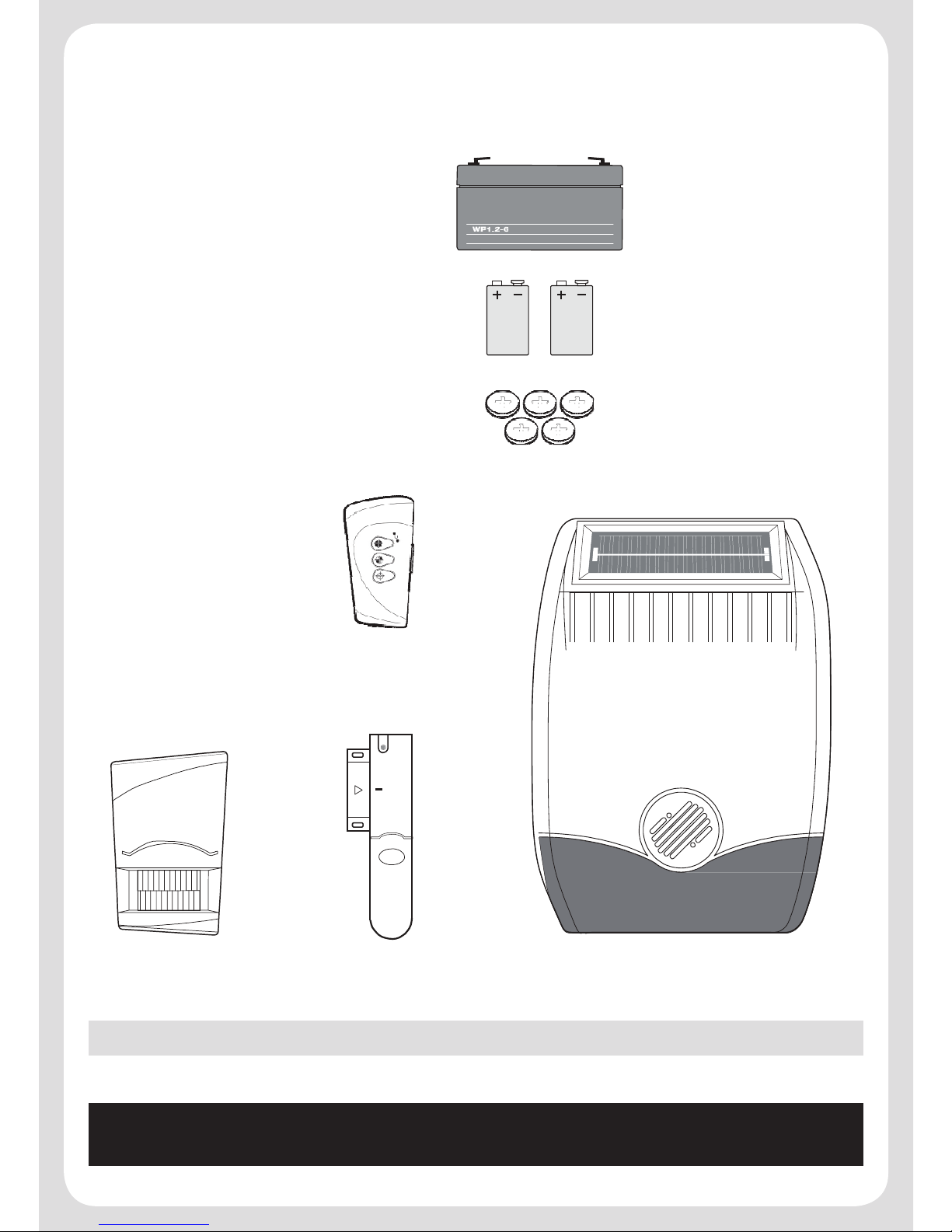
Kit Contents
Alarm Components:
1 x External Solar Siren
2 x PIR Movement Detectors
2 x Magnetic Contact Detectors
1 x Remote Control
Also included:
Instruction Guide
Fixing pack
PIR Movement
Detector
Magnetic Contact
Detector
Remote
Control
Batteries included:
1 x 6V/1.2Ah sealed lead
acid battery (for the Solar
Siren)
3 x 9V PP3 Alkaline battery
(for PIR Movement Detectors
and Solar Siren)
5 x 3V CR2032 Lithium cells
(for Remote Control and
Magnetic Contact Detectors)
External Solar Siren
Important: Please check all items listed above are included in the package.
Note: Diagrams are for illustration purposes only actual appearance may vary.
For a Control Panel operated system please refer to the Operating and
Installation Instructions supplied with the Control Panel

4
Introduction and Overview
System Arming
The system has an Instant-Arm and Delay-Arm mode. If the system is armed in Instant-Arm mode
then all detectors will immediately become fully armed. Any detector triggered while the system is
armed will immediately sound an alarm.
Entry / Exit Delay
If the system is armed in Delay-Arm mode this will activate the system with a 15 second entry/exit
delay period. This allows a 15 second period for the user to exit the property after setting the system
with the Remote Control. Any detector triggered while the system is armed will cause an alarm
condition after the 15 second entry/exit delay has expired. This allows time for the system to be
Disarmed before an alarm sounds when re-entering the property.
Note: To conserve power and maximise battery life the PIR Detector will only detect movement
if there has been no movement detected within the previous 2 minutes. Consequently the PIR
Detector will not become active until the protected area has been free from movement for more
than 2 minutes.
Alarm Lockout
If a detector is triggered while the system is armed, the alarm will sound. After the set alarm duration
has ended, the alarm will stop and the system will automatically reset. Subsequent detectors
triggered will again sound the alarm. If the alarm is triggered more than 3 times then it will become
‘Locked Out’ and any further alarm signals will be ignored until the system is re-armed.
Tamper Protection
All system devices (except the Remote Control) incorporate Tamper protection features to protect
against unauthorised attempts to interfere with the device.
Any attempt to remove the battery cover from any device (except a Remote Control) or to remove the
Siren from the wall will trigger an alarm (unless the system is in Service Mode), even if the system
is Disarmed.
Jamming Detection
In order to detect any attempts to illegally jam the radio channel used by your alarm system, a special
jamming detection function is incorporated in the Siren. If this feature is enabled, an alarm will be
triggered if the radio channel is jammed continuously for more than 30 seconds or if the system is
jammed for more than 3 periods of 10 seconds in a 5 minute period. (The Siren will emit a series of
rapid beeps for 5 seconds as a pre-alarm warning 10 seconds before a full alarm occurs).
The jamming detection circuit is designed to permanently scan for jamming signals. However, it is
possible that it may detect other local radio interference operating legally or illegally on the same
frequency. If it is planned to operate the jamming detection feature we recommend that the system
5
is monitored for false jamming alarms for at least 2 weeks prior to leaving the jamming detection
function permanently enabled.
Battery Monitoring
All devices powered by non-rechargeable batteries incorporate a battery level monitoring feature
which will warn of a low battery status. The batteries on any device indicating a low battery status
should be replaced immediately.
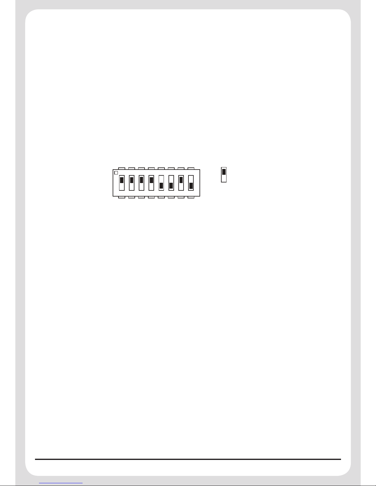
System House Code
In order to prevent any unauthorised attempt to operate or disarm your system, you must configure
your system to accept radio signals only from your own system devices. This is done by setting a
series of 8 DIP switches in all devices to the same ON/OFF combination (the House Code) selected
by the user/installer.
ON ECE
1 2 3 4 5 6 7 8
e.g.
Switch
= set to ON
position
The House Code is set up by moving each of the 8 DIP switches in each device to the same randomly
selected ON/OFF sequence. When setting the DIP switches, ensure that each switch ‘clicks’ fully into
position. Use the tip of a ballpoint pen or a small screwdriver to move each switch in turn.
All devices must be configured with the same House Code in order for the system to operate
correctly.
IMPORTANT: It is important that the system House Code is always changed to a code other than
the factory setting and that all devices are configured with the same House Code in order for the
system to operate correctly.
6
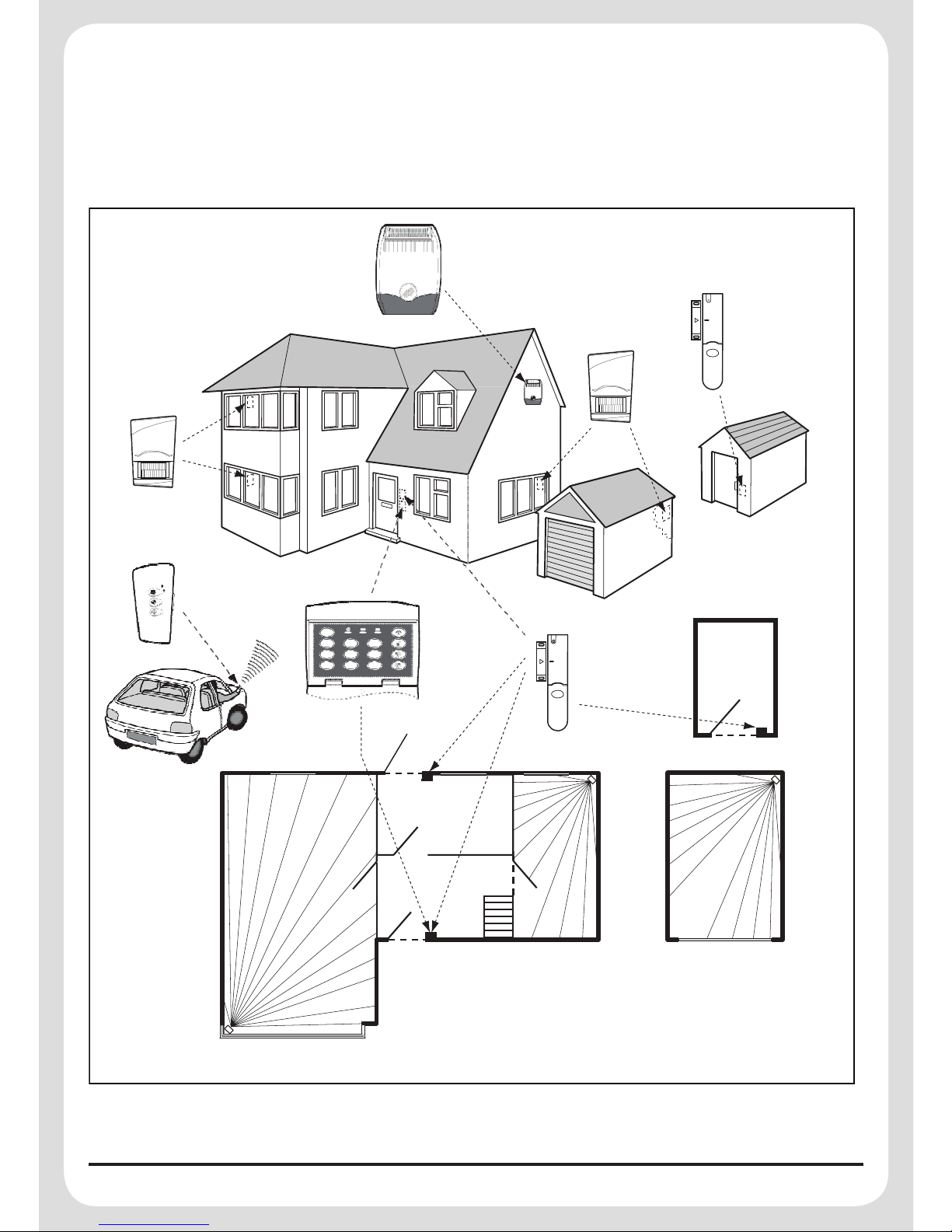
Planning and Extending your Wire Free Alarm System
The example below shows a typical property incorporating the suggested positions for the Remote
Keypad (optional accessory), PIR and Magnetic Detectors for optimum security. Use this as a guide
for your installation in conjunction with the recommendations contained in this manual for planning
your intruder alarm system.
0
1 2 3
4 5 6
7 8 9
External
Solar Siren
Magnetic Contact
Detector
PIR Movement
Detector
PIR Movement
Detector
Remote
Control
Remote
1
Keypad
2
Magnetic
Contact
Detector
SHED
Back Door
KITCHEN
HALL
DINING
ROOM
PIR
Movement
Detector
PIR
Movement
Detector
LOUNGE
GROUND FLOOR
GARAGE
PIR Movement
Detector
Before attempting to install your Alarm System it is important to study your security requirements
and plan your installation. The alarm system may be extended at any time to provide even greater
protection by fitting additional devices to meet your personal security needs.
7
Remote Control Unit
The Remote Control Unit is used to Arm and Disarm the system.
The Remote will activate the Instant-Arm, DelayArm or Disarm functions.
The Remote Control also incorporates a Personal
Attack Switch (PAS). Activating the PAS will
immediately initiate a Full Alarm condition whether
the system is Armed or Disarmed, (unless the
system is in Service, Test or Program mode).
Any number of Remote Controls can be used with
your system, providing they are all coded with the
same system House Code.
The Remote Control is powered by a CR2032 type Lithium Cell battery which under normal conditions
will have a typical life in excess of 1 year. Under normal battery conditions the LED on the Remote
Control will only illuminate when a button is pressed. However, under low battery conditions the LED
will flash every time the button is pressed. When this occurs the battery should be replaced as soon
as possible.
Setting the Remote Control
1. Remove the front cover by undoing the small screw on the rear of the Remote Control.
2. Located above the battery is a row of 8 DIP switches.
Select and record a random combination of ‘ON’ and
‘OFF’ positions for the DIP switches. This will be the
system House Code and must be set to the same ON/
OFF combination as the House Code DIP switches in
all other System Devices.
Important: The House Code for your system should
be changed from the factory default setting.
3. To utilise the panic facility on the Remote Control,
remove the Jumper Link. If ‘panic’ is not required
leave the Jumper Link in place.
4. Remove the battery from its packaging and insert it under the clip ensuring that the +v terminal
faces upwards away from the PCB.
5. Replace the front cover and fixing screw.
Testing the Remote Control
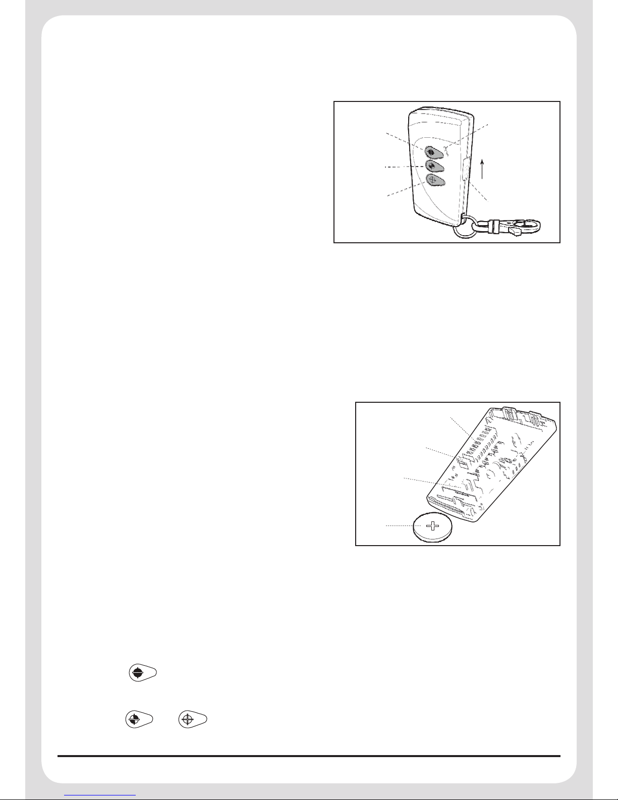
1. Press the button. The Transmit LED should illuminate while the button is pressed and
extinguish within 1 second of releasing the button.
2. Press the and buttons in turn to ensure that the Transmit LED illuminates as before.
Transmit LED
Arm
Delay-Arm
Slide up
to operate
Disarm
Personal Attack
House Code
Dip Switches
Jumper Link
Battery Clip
Battery
8
Passive Infrared (PIR) Movement Detectors
PIR Detectors are designed to detect movement in a protected area by detecting changes in infrared radiation levels caused, for example, when a person moves within or across the devices field of
vision. If movement is detected an alarm signal will be triggered, (if the system is armed).
Note: PIR Detectors will also detect animals, so ensure that pets are not in areas fitted with PIR
Detectors when the system is armed.
Any number of PIR Detectors can be used with your system providing they are all coded with the
system house code, and are mounted within effective radio range.
The PIR Detector is powered by a 9V PP3 alkaline battery. Under normal operating conditions this
will provide an expected life of up to 1 year. When the battery level becomes low the PIR Detector
will flash a red LED behind the lens. When this occurs the battery should be replaced as soon as
possible.
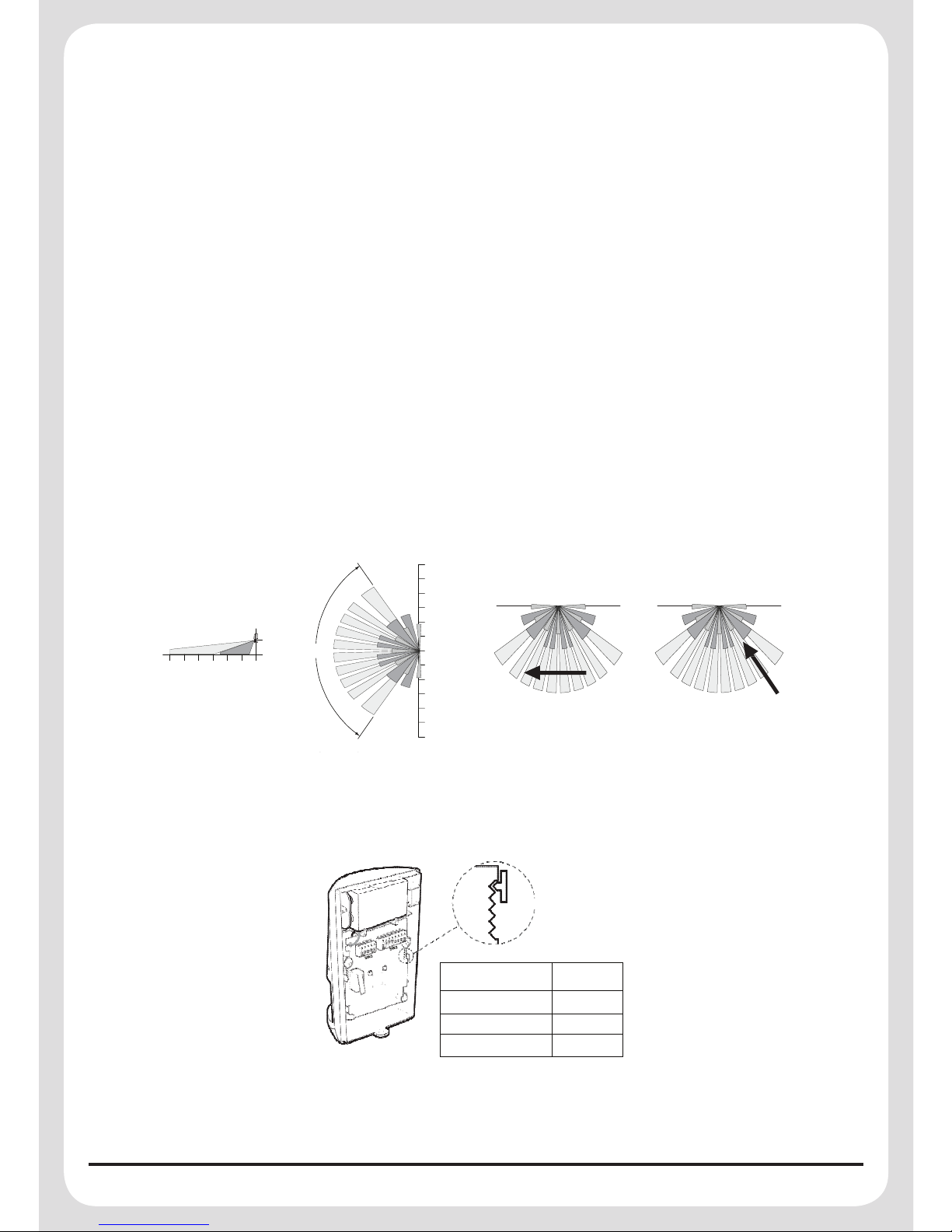
Positioning the PIR Detector
The recommended position for a PIR Detector is in the corner of a room mounted at a height of
between 2 and 2.5m. At this height, the PIR Detector will have a maximum range of up to 12m with
a field of view of 110°.
1210
Top View
8
6
4
2
2
0
110°
0
12 10 8
6
4
2
0
2
meters
Side View
4
6
8
10
12
meters
Movement direction and sensitivity
1210
Top View
8
6
4
2
2
0
110°
0
6
4
2
0
2
meters
Side View
4
6
8
10
12
meters
More Sensitive
Less Sensitive
The position of the PCB inside the PIR can be set to 5 different positions to adjust the range of
the PIR Detector. Setting the PCB in position 3 will reduce the range to 9m approximately, with
position 1 providing a range of 6m approximately. The recommended position setting for the PCB
is in position 5.
5
4
PCB Positions
3
Indicator
2
(positions 1-5)
1
PCB Position
Range
1
6m
3
9m
5
12m
Note: The range as indicated above refers to the linear distance in front of the PIR Detector.
9
When deciding upon the mounting position for the PIR Detector the following points should be
considered to ensure trouble free operation:
1. Do not position the PIR Detector facing a window or where it is exposed to or facing direct
sunlight. PIR Detectors are not suitable for use in conservatories or for external use.
2. Do not position the PIR Detector where it is exposed to draughts.
3. Do not position the PIR Detector directly above a heat source, (e.g. fire, radiator, boiler, etc).
4. Where possible, mount the PIR Detector in the corner of the room so that the logical path of an
intruder would cut across the fan detection pattern. PIR Detectors respond more effectively to
movement across the device than to movement directly towards it.
5. Do not locate the PIR Detector in a position where it is subject to excessive vibration.
6. Ensure that the position selected for the PIR Detector is within effective range of the System.
Note: When the system is armed, pets should not be allowed into an area protected by a PIR
Detector as their movement will trigger the PIR and generate an alarm.
Note: DO NOT fix the PIR Detector to metalwork or locate the unit within 1m of metalwork (i.e.
radiators, water pipes, etc) as this could affect the radio range of the device.
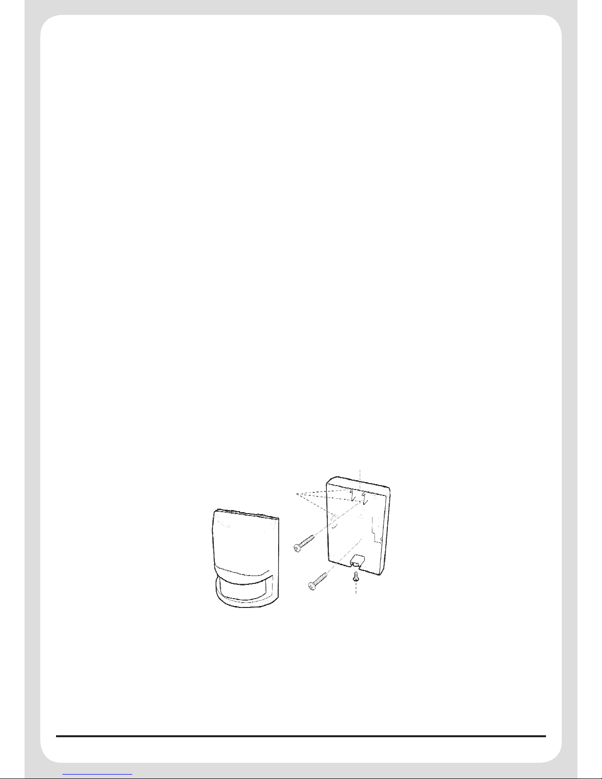
Installing and Configuring the PIR Movement Detector
Ensure that the system is in Service Mode
1. Undo and remove the fixing screw from the bottom edge of the PIR Detector. Carefully pull the
bottom edge of the PIR Detector away from the rear cover and then slide down to release the top
clips.
Mounting Hole
Positions
Rear Cover
Fixing Screw
2. Carefully drill the required mounting holes in the rear cover using a 3mm drill relevant to whether
the PIR Detector is being mounted in a corner or against a flat wall.
3. Using the rear cover as a template, mark the positions of the fixing holes on the wall.
4. Fix the rear cover to the wall using the two 18mm No.4 screws and 25mm wall plugs, (a 5mm
hole will be required for the wall plugs). Do not over-tighten the fixing screws as this may
distort or damage the cover.
 Loading...