

433MHz Wire Free
PIR Detector
LHD100SU
Instruction Guide
2
LuxHome
433MHz Wire Free
PIR Detector
These instructions should be read in conjunction with your System Installation
and Operating Instructions and be retained for future reference.
Introduction
The LuxHome PIR Detector is designed for use with LuxHome wire free Intruder Alarm
Systems operating on 433MHz only.
PIR Detectors are designed to detect movement in a protected area by detecting
changes in infrared radiation levels caused, for example, when a person moves within
or across the devices field of vision. If movement is detected an alarm signal will be
triggered (if the system and alarm zone is armed).
Note: PIR Detectors will also detect animals, so ensure that pets are not in areas fitted
with PIR Detectors when the system is armed.
Any number of PIR Detectors can be used with your system providing they are all
coded with the system house code, and are mounted within effective radio range.
The PIR Detector is powered by a PP3 alkaline battery. Under normal operating
conditions this will provide an expected life up to one year. When the battery level
becomes low the PIR Detector will flash a red LED behind the lens. When this occurs
the battery should be replaced as soon as possible.
Choosing a Position for the PIR Detector
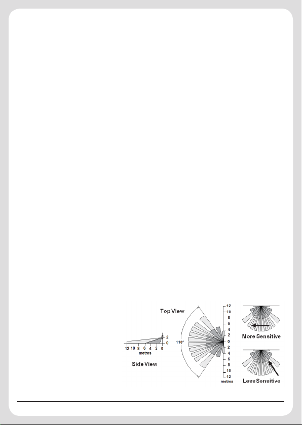
The recommended position
for a PIR Detector is in the
corner of a room mounted at
a height of between 2 and
2.5m. At this height, the PIR
Detector will have a maximum
range of up to 12m with a field
of view of 110°.
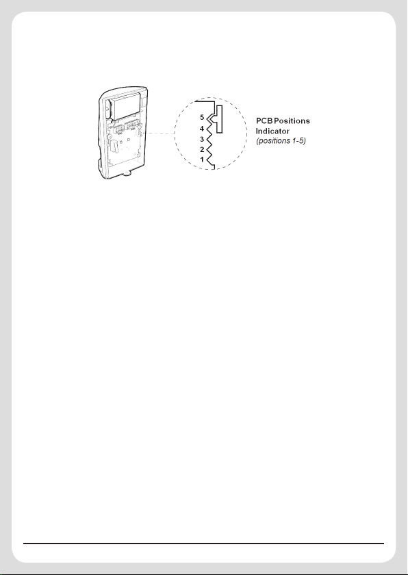
The position of the PCB inside the PIR can be set to 5 different positions to adjust
the range of the PIR Detector. Setting the PCB in position 3 will reduce the range
to 9m approximately, with position 1 providing a range of 6m approximately. The
recommended position setting for the PCB is in position 5.
Note: The range as indicated above refers to the linear distance in front of the PIR
Detector.
When deciding upon the mounting position for the PIR Detector the following points
should be considered to ensure trouble free operation:
1. Do not position the PIR Detector facing a window or where it is exposed to or
facing direct sunlight. PIR Detectors are not suitable for use in conservatories or for
external use.
2. Do not position the PIR Detector where it is exposed to ventilation facilities.
3. Do not position the PIR Detector directly above a heat source (e.g. fire, radiator,
boiler, etc).
4. Where possible, mount the PIR Detector in the corner of the room so that the
logical path of an intruder would cut across the fan detection pattern. PIR Detectors
respond more effectively to movement across the device than to movement directly
towards it.
5. Do not locate the PIR Detector in a position where it is subject to excessive
vibration.
6. Ensure that the position selected for the PIR Detector is within effective range of the
System.
Note: When the system is armed, pets should not be allowed to go into an area
protected by a PIR Detector as their movement will trigger the PIR and generate
an alarm.
3

4
Note: DO NOT fix the PIR Detector to metalwork or locate the unit within 1m of
metalwork (i.e. radiators, water pipes, etc) as this could affect the radio range of
the device.
Installing and Configuring the PIR Detectors
Ensure that the system is in Test or Service Mode
1. Undo and remove the fixing screw from
the bottom edge of the PIR Detector.
Carefully pull the bottom edge of the PIR
Detector away from the rear cover and
then slide down to release the top clips.
2. Carefully drill the required mounting
holes in the rear cover using a 3mm drill
relevant to whether the PIR Detector is
being mounted in a corner or against a
flat wall.
3. Using the rear cover as a template, mark
the positions of the fixing holes on the
wall.
4. Fix the rear cover to the wall using the two 18mm No.4 screws and 25mm wall
plugs (a 5mm hole will be required for the wall plugs). Do not over-tighten the fixing
screws as this may distort or damage the cover.
Note: The wall plugs supplied with the product are not suitable for plasterboard
walls, if mounting the PIR Detector onto plasterboard use appropriate wall plugs.
5. Configure the PIR Detector as described below. Remember that on initial installation
the device needs to be tested and should therefore be set in Walk Test Mode.
6. Check that the PIR Detector PCB is located and set in the correct position to give
the detection zone pattern required.
To adjust the PCB position, simply slide it up or down ensuring that the location legs
are aligned with the required position number marked on the board.
7. To refit the PIR Detector to the rear cover, offer it up to the rear cover and locate
the clips in the top edge into the rear cover. Push the lower edge of the PIR into
place and refit the fixing screw in the bottom edge to secure in position. Do not overtighten the fixing screws as this may damage the casing.

Setting the PIR Detectors
Located on the PCB of the PIR
Detector are two blocks of DIP
switches (SW2 and SW3). When
setting Dip Switches to House
Code, hold the PIR Detector ‘upside
down’ as shown in the diagram on
the right:
1. DIP switches SW2 (numbered
1-8) are used to set the House
Code for the PIR Detector and
must be set to the same ON/OFF
combination as the House Code
DIP switches in all other system
devices.
2. Set the alarm zone which the PIR
Detector will operate on, with DIP
switches 1-3 of SW3 as follows:
Setting for Siren only Alarm System
For a Siren only Alarm System, DIP switches 1-3 of SW3 must be set as follows:
DIP 1 DIP 2 DIP 3
ON ON OFF
Setting for an Alarm System with a Control Panel
If your system has a Control Panel, DIP Switches 1-3 of SW3 should be set as
follows:
DIP 1 DIP 2 DIP 3
Zone 1 OFF OFF OFF
Zone 2 OFF OFF ON
Zone 3 OFF ON OFF
Zone 4 OFF ON ON
Zone 5 ON OFF OFF
Zone 6 ON OFF ON
5

6
3. DIP 4 of SW3 is used to configure the PIR Detector for walk test mode, which allows
the operation of the Detector to be checked during installation without triggering a
Full Alarm.
DIP 4 of SW3 Mode Trigger reaction on LED
• LED single flash when
movement detected: implies
the sensor is set to high
ON
Walk
Test
sensitivity
• LED flashes three times and
illuminates once: implies
the sensor is set to low
sensitivity
OFF
Normal
Position
LED will not light up (unless the
battery in the PIR is low)
Note: On initial installation the PIR Detector should be set to Walk-Test mode ready
for testing.
4. The PIR Detector incorporates a sensitivity feature designed to compensate for
situations where the Detector may be affected by environmental changes, (e.g.
insects, air temperature, etc). This feature is called “Detection Sensitivity” and may
be set to Standard or High Sensitivity.
Note: The higher the sensitivity the less movement will be necessary before the
PIR Detector will trigger the alarm.
The recommended setting is Standard Sensitivity. If set to High Sensitivity, in some
cases extreme environmental problems could cause unexplained false alarms.
If this is experienced it may be necessary to reset the PIR Detector to Standard
Sensitivity.
Set the required detection sensitivity using DIP 5 of SW3 as follows:
OFF Standard Sensitivity
ON High Sensitivity
5. Connect the PP3 alkaline battery to the battery clip.
Note: When the 9V alkaline battery is connected, the LED behind the lens will flash
for 2-3 minutes until the PIR has warmed-up and stabilized. The LED will then stop
flashing and turn OFF.

Testing the PIR Detector
Before testing the PIR Detector ensure that the system is in Test mode (for a
Control Panel System) or Service Mode (for a Siren only System).
With the PIR Detector set in Walk Test mode (Switch 4) and mounted in position on
the wall, allow 2-3 minutes for the PIR Detector to stabilize before commencing the
Walk Test.
1. Walk into and move slowly around the protected area, each time the PIR Detector
senses your movement the LED behind the Lens will flash.
If necessary re-adjust the detection pattern by changing the mounting position of
the PCB within the PIR housing.
2. Reconfigure the PIR Detector for normal operation mode by setting DIP4 of SW3 to
OFF and refit in position.
Note: In normal operation, the LED behind the PIR Detector lens will not flash on
movement detection, (unless the battery is low).
Note: When the PIR Detector is fully installed i.e. battery cover is refitted; the
unit will not detect movement for approximately 45 seconds after each activation.
(This feature is present to conserve battery power and maximize the battery life).
7

Disposal and Recycling
Disposal of this product is covered by the Waste Electrical or Electronic Equipment
(WEEE) Directive.
It should not be disposed of with other household or commercial waste.
At the end of its useful life the packaging and product should be disposed of via
a suitable recycling center. Please contact your local authority or the retailer from
where the product was purchased for information on available facilities.
Guarantee
The product is guaranteed for one year from the date of purchase against faulty materials and
workmanship. No liability can be accepted for any problems caused by fair wear and tear, buyer’s
negligence, improper fitting or use, wilful or accidental damage, or any consequential loss or
damage howsoever caused. This guarantee does not affect your statutory rights and is valid for
the country or region of your purchase.
If you believe the product to be faulty or in the unlikely event of the product developing a fault
during the warranty period, then please contact your supplier for product assistance. Product
repair or replacement will be offered for faulty products only with our prior agreement. Should you
need to return a product then:
1. Contact your supplier and obtain a Return Authorisation Number.
2. Adequately package your product to prevent damage in transit and include the following:
a. A copy of your original invoice/receipt.
b. A covering letter giving your full contact details, including email address (if applicable).
c. A description of the fault or problem.
LuxHome Alarm Systems
Manufactured by Everspring
Copyright © 2013. All Rights Reserved.
Everspring Industry Co., Ltd.
Website: www.everspring.com
Service Support: sales@everspring.com
8
A501112101R V1.0 2013/06
 Loading...