

433MHz Wire Free
Keypad Control Panel
LHC110SU
Instruction Guide
2
LuxHome
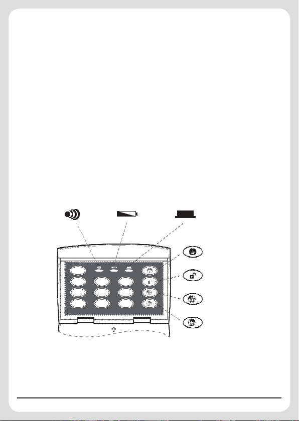
Transmit
Indicator
LED
0
Low Battery
Indicator
LED
Key Pressed
Confirmation
Indicator LED
Arm
Disarm
1
2 3
4 5 6
1
7 8 9
2
Part-Arm 1
1
or Delay Arm
Part-Arm 2
2
or Delay Arm
Fig. 1 Wireless Keypad Function Guide
433MHz Wire Free
Keypad Control Panel
These instructions should be read in conjunction with your
System Installation and Operating Instructions and be retained
for future reference.
Introduction
The LuxHome Wire Free Keypad Control Panel (hereafter referred
to as Keypad) is designed for use with LuxHome Wire Free Intruder
Alarm systems operating on 433MHz only.
The Keypad controls the system by using a four digit User Access
Code. The Keypad incorporates panic and anti-tamper protection

features that will immediately initiate a Full Alarm condition when
activated. Any attempt to open the casing of the Keypad will
immediately initiate a Full Alarm condition even if the system is
disarmed, (unless the system is in Service, Test or Programming
modes). In addition if a sequence of more than 16 incorrect key
presses are entered the Keypad will be disabled for one minute.
During this one minute period the LED will keep flashing slowly.
If consecutively disabled three times, the Keypad will emit the
tamper signal and initiate a Full Alarm condition.
The Keypad’s User Access Code is independent from any other
access codes.
The Keypad is powered by a 9V PP3 Alkaline battery. Under
normal operating conditions this will provide an expected life of
up to one year. When the battery level falls below an acceptable
level, the “LOW BATTERY” indicator on the front of the Keypad will
flash. When this occurs the battery should be replaced as soon as
possible.
Positioning the Keypad
The Keypad is rated IP44 and suitable for mounting outdoors. The
Keypad should be mounted in a position close to the main entrance
door so that the user access code can be entered easily.
Ensure that the position selected for the Keypad is within the
effective range of the Siren or Control Panel.
Note: DO NOT fix the Keypad to metalwork or locate the unit within
1m of metalwork (i.e. radiators, water pipes, etc) as this could affect
the transmission range of the Keypad.
3
4
Installing and Configuring the Keypad
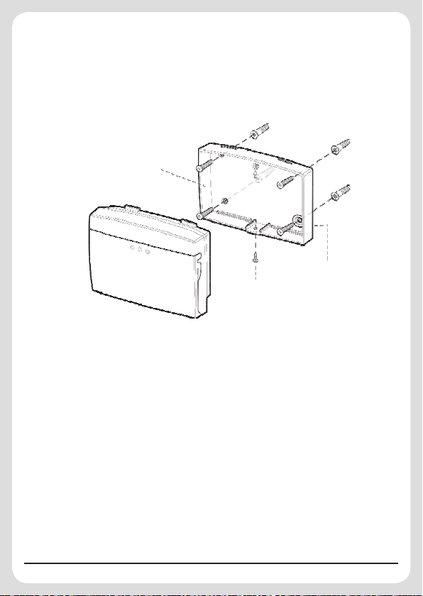
Fig. 2
Wall Mounting Plate
Fixing
Screw
Anti-Tamper
Protection
If you have a system with a main Control Panel, ensure it is in
Test or Programming Mode. If you have a system without a Control
Panel, ensure that the Siren is in Service mode.
1. Undo and remove the fixing screw from the bottom edge of the
Keypad and remove the wall mounting plate. (Fig. 2).
2. Using the mounting plate as a template to mark the positions of
the four fixing holes on the wall.
Note: To make the best use of anti-tamper protection you
must insert a wall plug and screw in the specified hole (as
illustrated).
3. Fix the mounting plate to the wall using the screws and wall plugs
provided, (a 5mm hole will be required for the wall plugs). Do
not over-tighten the fixing screws as this may distort or damage
the mounting plate.
Note: Installing the Keypad against a flat and smooth wall is of
great importance so as to avoid the tamper switch being falsely
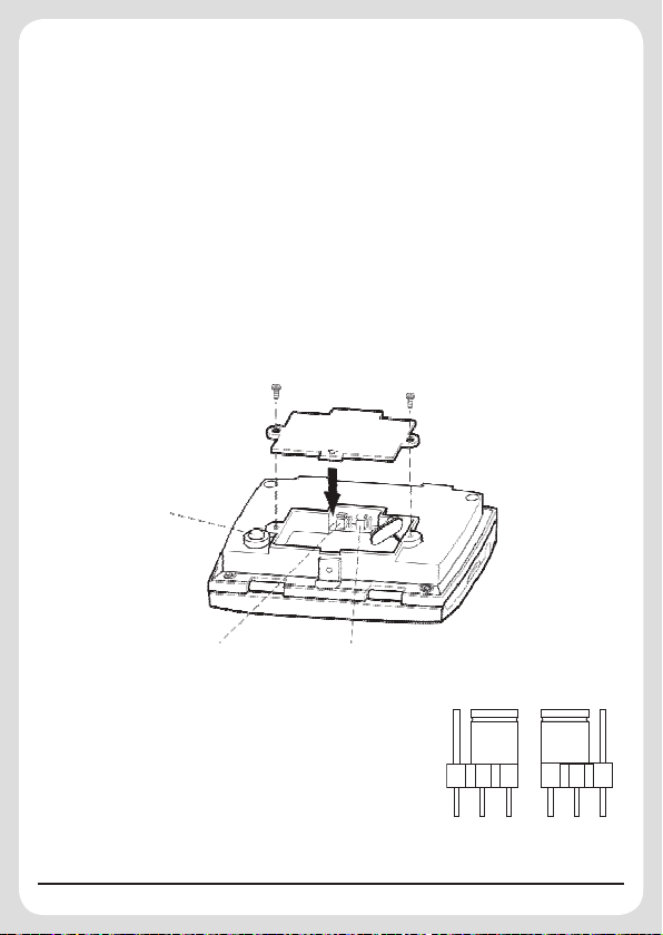
Fig. 3
Anti-Tamper
Switch
System Type
Jumper
Link J3
Reset
Jumper
Link J2
1 J 3
1
J 3
Fig. 4a Fig. 4b
1
J 3
triggered.
Note: The wall plugs supplied with the product are not suitable for
plasterboard walls. If mounting the Keypad on to a plasterboard
use appropriate wall plugs.
4. Undo and remove the two fixing screws in the rear of the Keypad
and remove the rear battery cover. (Fig. 3).
5. There are two jumper links located above the battery
compartment. (Fig. 3)
J2 jumper link: Reset to Factory default
J3 jumper link: System type selection
If the Keypad is to be used with a Siren
Controlled System, then the jumper link
J3 must be set as shown on Fig. 4a. If
your system has a separate Control
Panel, the jumper link J3 must be set as
shown on Fig. 4b.
5

6
To verify the compatibility of your system, follow two steps for
1
2
Fig. 5
testing: 1) Connect the PP3 battery. 2) Press
and
together for more than 2 seconds. The Keypad will send the
Panic signal to the Control panel/Siren. If the Control panel/
Siren does not react, adjust the jumper link J3 accordingly.
6. Seat the PP3 battery into the battery compartment.
7.
Replace the rear cover and refit fixing screws. Do not over-tighten
the fixing screws.
8. Refit the Keypad by slanting 45° onto the wall mounting plate.
Do not over-tighten the fixing screw. (Fig. 5).
Note: The Keypad is supplied with a default User Access Code
of: 1234. For security reasons, it is recommended that this
code is changed to another four digit number which only you and
other users of the system know.
Note: Use thumb and middle finger to hinge down the Keypad
cover. (Fig. 6) The Keypad has a back light illumination facility.
It will illuminate for 5 seconds when you open the Keypad cover
or press any key.

Fig. 6
Testing the Keypad
? ? ? ?
,
User Access Code
1
2
? ? ? ?
,
User Access Code
? ? ? ?
,
User Access Code
Ensure that the Control panel/Siren is in Test or Programming
Mode.
1. Press
2. Press and hold
and
approximately 2 seconds, an alarm will be initiated.
3. Press
Operating the Keypad
Arm:
Press
.
7
to arm the system.
buttons together, after
to disarm the system.

8
Part-Arm: (for Control Panel Systems)
? ? ? ?
,
User Access Code
1
? ? ? ?
,
User Access Code
2
? ? ? ?
,
User Access Code
1
? ? ? ?
,
User Access Code
2
? ? ? ?
,
User Access Code
1
2
Press
Press
for Part-Arm 1.
for Part-Arm 2.
Delay-Mode: (for Siren Only Systems)
To Arm the system in Delay Mode enter the User Access Code
followed by either of the ‘DELAYARM’ buttons on the Keypad:
OR
The Siren will acknowledge the signal by beeping once and then
again after the 15 second exit delay.
Disarm:
Press
.
Panic:
Default setting: On
Press and hold
and
buttons together for more than 2
seconds with LED flashing rapidly.
To enable or disable the panic function, follow the below steps in
sequence:

Enabling the Panic function:
? ? ? ?
,
User Access Code
1
!
2
? ? ? ?
,
User Access Code
1
!
2
1. Press 2.
2. Enter
.
3. Press 2; the LED will illuminate once and flash twice.
4. Press
5. Press
.
; the LED will illuminate once and flash three
times to confirm the setting has been accepted.
Disabling the Panic function:
1. Press 2.
2. Enter
.
3. Press 2; the LED will illuminate once and flash twice.
4. Press
5. Press
0
.
; the LED will illuminate once and flash three
times to confirm the setting has been accepted.
9

10
Inputting the House Code
? ? ? ?
,
User Access Code
? ? ? ?
,
In order to prevent any unauthorised attempt to operate or disarm
your system; you must configure your system to accept radio
signals only from your own system devices. This is done by setting
a series of eight miniature (DIP) switches in all devices to the same
ON/OFF combination (The House Code) selected by the user/
installer. This Keypad is designed to be fixed outdoors. For security
reasons, it does not include a DIP switch, but house code setting
is still required.
To input the house code, press the following keys in sequence:
1. Press .
2. Enter
.
3. Press ; the LED will illuminate once and flash twice.
4. Press
which is House Code to be set on
Keypad (up to 8 digits).
5. Press
; the LED will illuminate once and flash three
times to confirm the setting has been accepted.
Example: Dip switch settings for your House Code are Dip Switch
numbers 1, 2, 5, 7, 8 set to the “ON” position, while 3, 4, 6 are set to
the “OFF” position. The input for the House Code on the Keypad
is 12578.
Resetting to Factory Default
If you forget the User Access code, you can reset the User Access

code to factory default by following the steps below:
? ? ? ?
,
? ? ? ?
,
1 J 2
1
J 2
Fig. 7a Fig. 7b
1. Remove the battery.
2. Press and hold any key for more than 1
second.
3. Set the Jumper link J2 as shown on Fig.
7b.
4. Refit the battery and test it by pressing the default User Access
code of 1 2 3 4.
5. If the testing is ok, set the jumper link J2 as shown on Fig. 7a,
which is what the Keypad is set to normally.
Changing the User Access Code
Default Code: 1 2 3 4
When using the Keypad the keys must be pressed firmly and
within five seconds of each other. If you make a mistake, wait five
seconds and recommence programming from the beginning of the
sequence. To change the User Access Code, press the following
keys in sequence:
1. Press 1.
2. Enter the existing User Access Code
3. Press 1; the LED will illuminate once and flash twice.
4. Press your new User Access Code
11
.
.

12
5. Press
1
; the LED will illuminate once and flash three
times to confirm the setting has been accepted. If the LED
does not flash, wait five seconds and re-enter the programming
sequence from the beginning.
Disabling the Keypad
If a sequence of more than 16 incorrect key presses is entered
the Keypad will be disabled for 1 minute. If consecutively disabled
3 times, the Keypad will emit a Tamper signal to the control panel
with LED flashing slowly.
Note: When the Keypad is disabled for 1 minute, the LED will
flash slowly, indicating that the Keypad is shut down temporarily.
During this 1 minute, any key presses will be treated as invalid
pressing. After the elapse of 1 minute, correct inputting will be
accepted.
Replacing the Batteries
The “LOW BATTERY” indicator on the front of the Keypad will not
flash until the Keypad emits a radio signal. Therefore the “LOW
BATTERY” indication won’t be seen in normal circumstance. The
batteries should be replaced as soon as possible as follows:
1. Press the User Access code twice, and the two LEDs ( &
) will keep flashing for 20 seconds. During this 20 seconds
duration, no radio signal will emit and any inputting will not be
accepted. In this way, the Keypad won’t emit radio signal when
replacing the battery.
2. Undo the fixing screw at bottom of Keypad and remove from the
wall mounting plate.

3. Undo the two fixing screws in the rear cover and remove the
? ? ? ?
,
User Access Code
? ? ? ?
,
User Access Code
battery cover.
4. Replace battery with a new 9V PP3 Alkaline battery.
5. Replace and fix the rear battery cover and then refit and secure
the Keypad onto the wall plate.
Solar Siren Operating Mode
Solar Siren ON
To switch the Solar Siren into Operating Mode:
Press
(and hold) for approx 10
seconds until the siren emits a single long beep and long flash.
Solar Siren OFF
To switch the Solar Siren off:
Press
(and hold) for approx 10
seconds until the siren emits a single long beep and long flash.
The Disarm key should be released after the long beep.
Anti-tamper Protection
The Keypad incorporates anti-tamper protection features to guard
against unauthorised attempts to remove the Keypad from the wall.
If the Keypad is removed from the wall, a full alarm condition will
be initiated.
13

Troubleshooting
Status Possible Cause Remedy
No function 1. Battery too low
LED flash
2. Wrong coding
3. Battery low 3. Replace with a new battery
1. Replace with a new battery
2. Check if the HOUSE CODES are exactly the same
Disposal and Recycling
Disposal of this product is covered by the Waste Electrical or Electronic Equipment
(WEEE) Directive.
It should not be disposed of with other household or commercial waste.
At the end of its useful life the packaging and product should be disposed of via a
suitable recycling center. Please contact your local authority or the retailer from where
the product was purchased for information on available facilities.
Warranty
The product is warranted for two years from the date of purchase against faulty materials and
workmanship. No liability can be accepted for any problems caused by fair wear and tear, buyer’s
negligence, improper fitting or use, wilful or accidental damage, or any consequential loss or
damage howsoever caused. This warranty does not affect your statutory rights and is valid for the
country or region of your purchase.
If you believe the product to be faulty or in the unlikely event of the product developing a fault
during the warranty period, then please contact your supplier for product assistance. Product
repair or replacement will be offered for faulty products only with our prior agreement. Should you
need to return a product then:
1. Contact your supplier and obtain a Return Authorisation Number.
2. Adequately package your product to prevent damage in transit and include the following:
a. A copy of your original invoice/receipt.
b. A covering letter giving your full contact details, including email address (if applicable).
c. A description of the fault or problem.
LuxHome Alarm Systems
Manufactured by Everspring
Copyright © 2013. All Rights Reserved.
Everspring Industry Co., Ltd.
Website: www.everspring.com
14
A501112120R V1.0 2013/08
 Loading...