

Lux Elements CONCEPT-BA-EH ZA, CONCEPT-BA-EH ZB, CONCEPT-BA-EH Series, CONCEPT-BA-EH ZC Mounting And Operating Instructions
www.luxelements.com
LUX ELEMENTS®-CONCEPT-BA-EH ...
Mounting and operating instructions
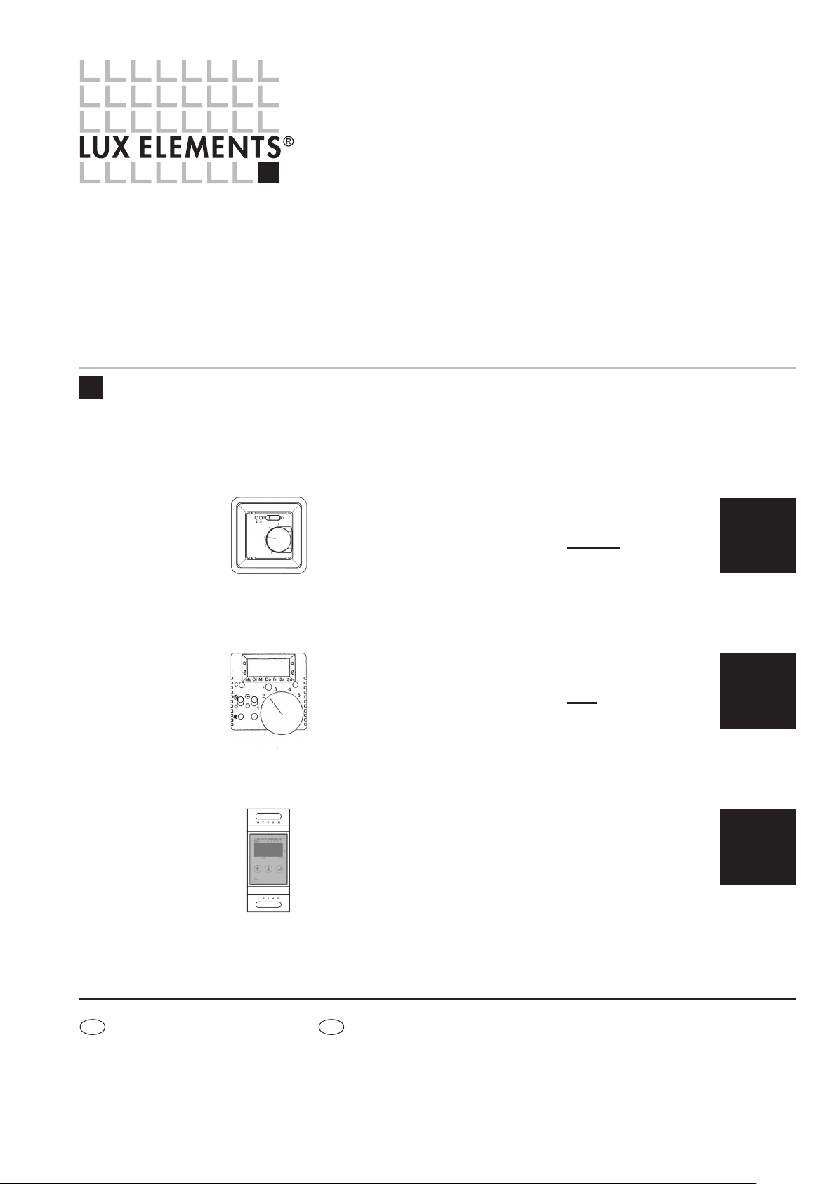
LUX ELEMENTS®-CONCEPT-BA-EH ZA
electronic temperature controller without timer
for flush mounting (12 A, 230 V AC)
... see page 2
LUX ELEMENTS®-CONCEPT-BA-EH ZB
electronic temperature controller with timer
for flush mounting (12 A, 230 V AC)
... see page 4
LUX ELEMENTS®-CONCEPT-BA-EH ZC
electronic temperature controller
for mounting in distribution cabinet (6A, 230 V AC)
... see page 7
ZA
ZB
ZC
DF
LUX ELEME NTS G mbH & Co. KG
An der Schusterinsel 7
D - 51379 Leverkusen-Opladen
Tel. +49 (0) 21 71/7212 -0
Fax +49 (0) 2171/7212 - 10
info@luxelements.de
www.luxelements.com
LUX ELEME NTS S .A.S
ZI- 31, rue d’Ensisheim
F - 68190 Ungersheim
Tél. +33 (0) 3 89 83 69 79
Fax +33 (0) 3 89 48 83 27
info@luxelements.fr
www.luxelements.fr
EN · 08/2017 · PROS3129
We reserve the right to make technical changes.
LUX ELEMENTS®-CONCEPT-BA-EH ZA
Electronic temperature controller without timer ( 12 A, 230 V AC)
LUX ELEMENTS®-CONCEPT-BA-EH ZB see page 4 / LUX ELEMENTS®-CONCEPT-BA-EH ZC see page 7
IMPORTANT NOTE
CAUTION: · Work on the 230 V mains supply may only be carried out by a qualified electrician.
· The national (Germany: VDE) and local electricity supply company safety regulations must be complied with when connecting the appliance.
CAUTION: · In the event of a fault, mains voltage may be present on the sensor cable. Connecting cables must be straight and the insulation stripped by about 6 mm.
· The sensor cable must be laid in a separate protective pipe and must not be laid together with cables that conduct mains voltage.
CAUTION: · Type of protection IP 30 = no protection against penetrating water!
· The controller must be protected from moisture and water vapour (relative air moisture < 60%).
Please refer to our data sheets. Valid data sheets and test certificates can be downloaded from www.luxelements.com.
ZA
TECHNICAL DATA
n
Operating range: 230 V/50 Hz
n
Control range: 10 ... 50 °C
n
Switching difference: approx. 1 K
n
Power consumption: approx. 1 VA
n
Temperature decrease: approx. 5K (fixed); (connection –> )
n
Contact: make contact, max. 230V~, max.16(2)A /
30,000 operating cycles
Certified by VDE for up to 12 (2) A /
100,000 operating cycles
n
External sensor: 2k, NTC acc. to. DIN 44574
(double-insulated) in compliance with DIN EN 60730-2-1
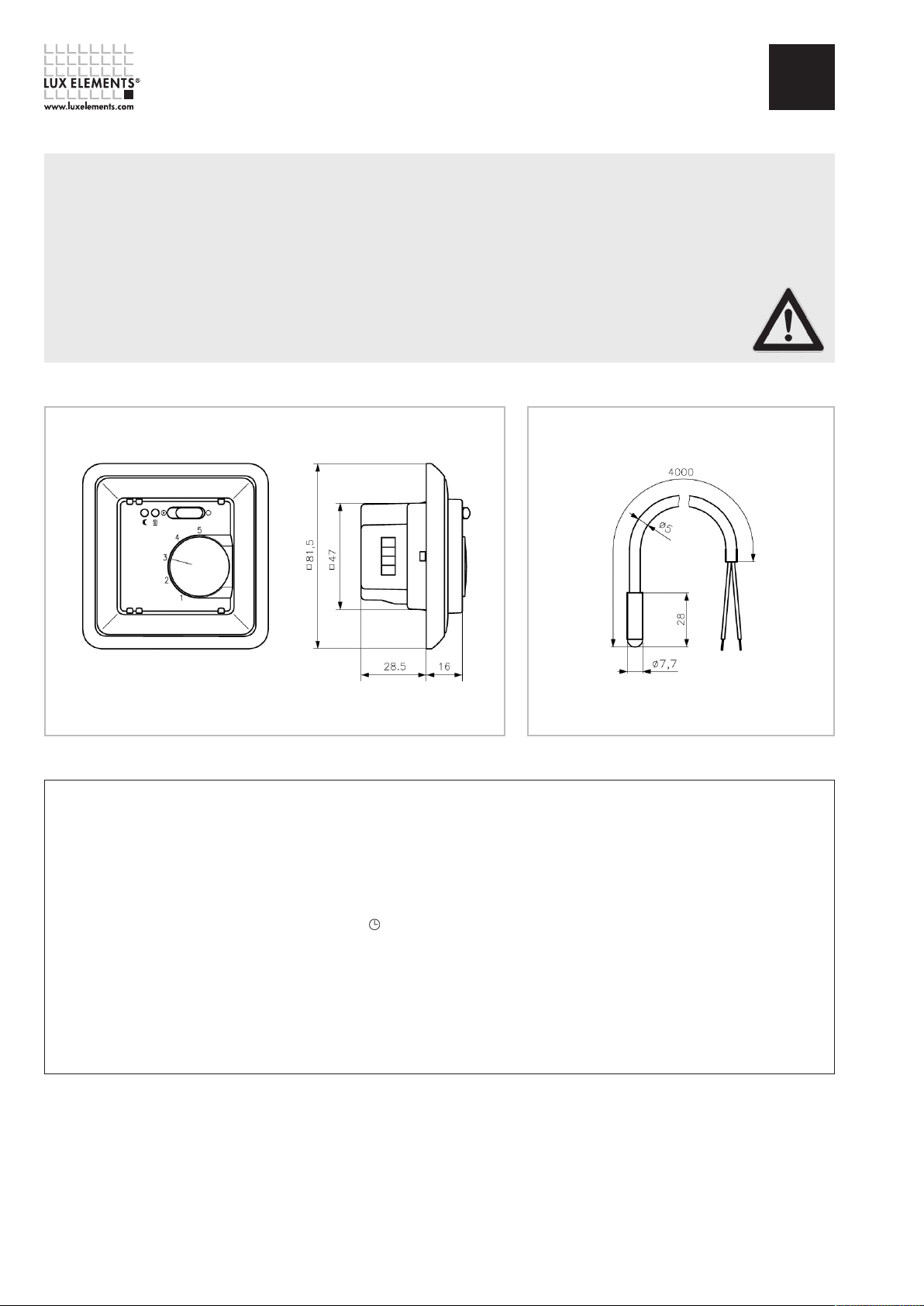
Dimensions in mm
Dimensions SensorDimensions Controller
n
Sensor breakdown detection: heating is turned off
n
Indicators: red LED for ‘heating‘ and green LED
for ‘night decrease mode‘
n
Terminal screws: 0,5 – 2,5 mm
n
Mounting: in an UP box (Ø 55 mm)
n
Degree of protection: IP 30
n
Protection class: II (after corresponding installation)
n
Ambient temperature: 0 ... 40 °C
n
Storage temperature: -20 ... +70 °C
n
Radio interference suppression: acc. to EN 50081-1 and EN 50082-1
2
Dimensions in mm
VDE = German Electrical Engineering Association
Page 2 – LUX ELEMENTS®-CONCEPT-BA-EH ZA
LUX ELEMENTS®-CONCEPT-BA-EH ZA
Electronic temperature controller without timer ( 12 A, 230 V AC)
LUX ELEMENTS®-CONCEPT-BA-EH ZB see page 4 / LUX ELEMENTS®-CONCEPT-BA-EH ZC see page 7
ZA
Area of application / functional method
Application example for the electric bench heating: The control variable is the bench temperature.
This is measured by means of the remote sensor at the heating mat level. The appliance comprises
the control module for setting the desired temperature and a temperature sensor which measures
the temperature and communicates the measured value to the control module
.
Functioning
The controller measures the temperature by means of a remote sensor which is placed inside
the building component. In case the temperature adjusted at the set value knob is underrun,
the contact with the heating is closed down (scale 1 ... 5 corresponds to ca. 10 ... 50 °C
temperature). The active state of the heating system is indicated by the red lamp. The heating
system can be deactivated with the switch. When connecting the phase to the terminal ,
the controller decreases the adjusted set value by approx. 5K. The green lamp indicates the
active state of this energy saving mode.
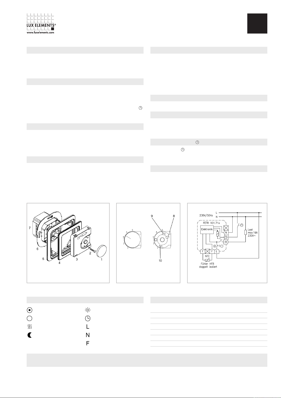
Opening the controller
·Lift out the thumb wheel (1) carefully using a screw driver
·Unscrew the fixing screw (2)
·Remove controller cover (3)
·Take off intermediate frame (4) and switch frame (5)
Installation controller
Caution, switch off mains voltage at all poles before installation!
·Electric connection according to ‘schematic diagram‘ with screw terminals
·Cross section of solid wire is load-dependant 1,5 ... 2,5 mm
·No protective conductor
·Install controller (7) in the flush-mounted box on the wall by means of a support ring (6)
and screws.
2
Installation sensor
·Between heating loops without contact
·Sensor lead inside protective tube
·Parallel laying with power cord prohibited
·Extension up to 50 m with 0.5 mm
·In the event of a fault or false connection, mains voltage may be present on the sensor.
Therefore, the sensor is double insulated according to EN 60730-2-1. Extension is only
permitted, using double insulation according to EN 60730-2-1.
2
(flexible conductors with cable end sleeve)
Close down device
·Close down of the device is effected in reverse order to opening.
Limitation of the setting range
·Remove pin (8)
·Turn red pin (9) for maximum temperature and blue pin for minimum temperature
·For fixation of the limits, plug-in the pin (8)
Connection of night decrease
If connected to terminal , night decrease is activated. This can be effected e.g. by a timer
or a watch regulator. (Caution! Two supplies) – if working at connector, the night decrease
is to be turned off as well.
Accessories
The controller is completely supplied with 4 m sensor sleeve (order designation HF-8/4-K2).
Explanation of symbols
Control ON (red)
Control OFF
Heating ON
Night decrease ON (green)
Limitation of the setting range Connection diagramMounting controller
Sensor characteristic curve
Heating connection
Connection Temperature decrease
Phase connection
Neutral conductor connection
Sensor connection
Temperature [°C] Resistance [k-Ohm] U [V]
10 3,66 2,49
20 2,43 2,22
25 2,00 2,08
30 1,65 1,92
40 1,15 1,63
50 0,82 1,35
Please refer to our data sheets. Valid data sheets and test certificates can be downloaded from www.luxelements.com.
LUX ELEMENTS®-CONCEPT-BA-EH ZA – Page 3
 Loading...