

Lux Elements CONCEPT-BA-EH ZA, CONCEPT-BA-EH ZB, CONCEPT-BA-EH, CONCEPT-BA-EH ZC Mounting And Operating Instructions
Page 1
www.luxelements.com
LUX ELEMENTS®-CONCEPT-BA-EH ...
Mounting and operating instructions
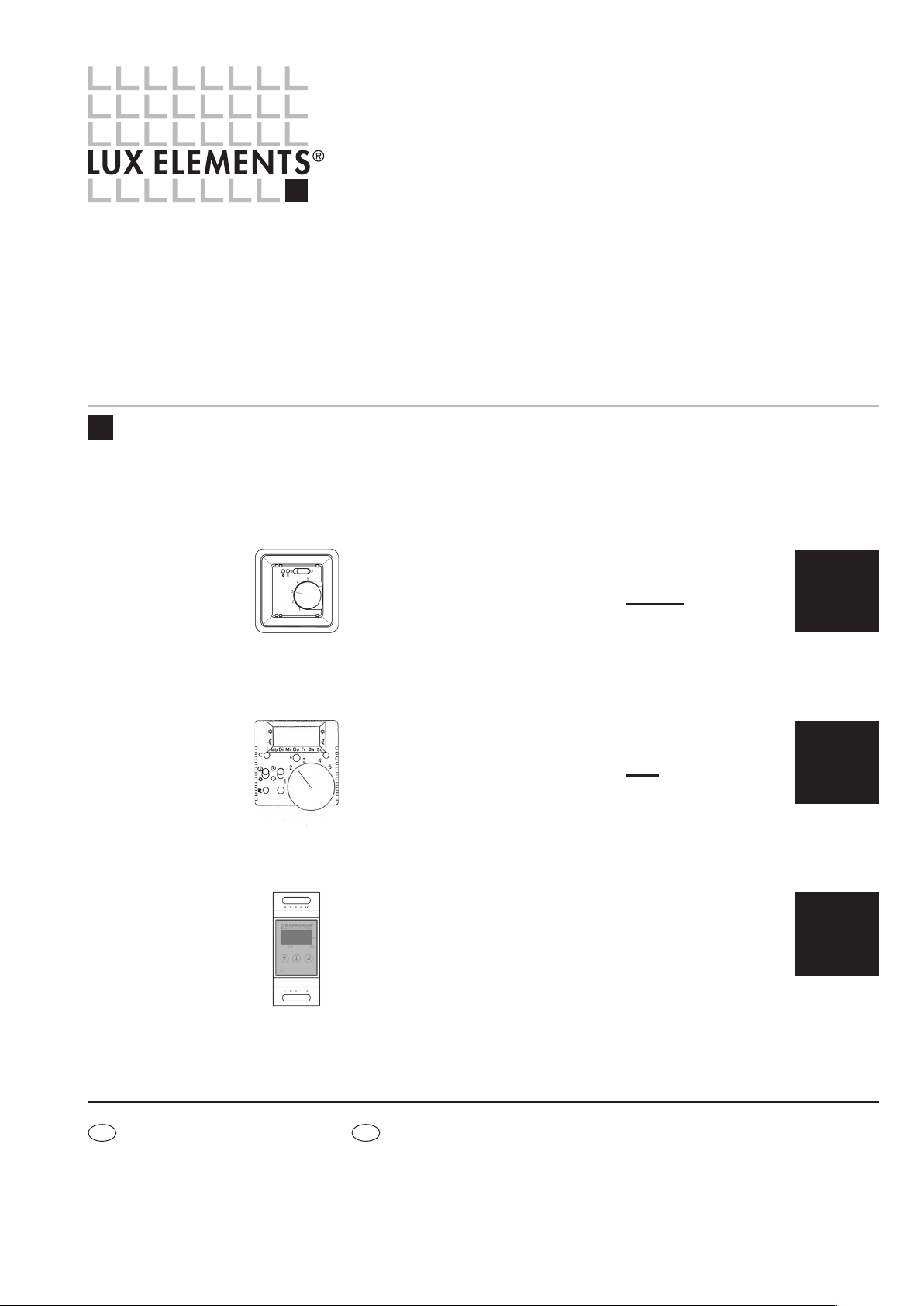
LUX ELEMENTS®-CONCEPT-BA-EH ZA
electronic temperature controller without timer
for flush mounting (12 A, 230 V AC)
... see page 2
LUX ELEMENTS®-CONCEPT-BA-EH ZB
electronic temperature controller with timer
for flush mounting (12 A, 230 V AC)
... see page 4
LUX ELEMENTS®-CONCEPT-BA-EH ZC
electronic temperature controller
for mounting in distribution cabinet (6A, 230 V AC)
... see page 7
ZA
ZB
ZC
DF
LUX ELEME NTS G mbH & Co. KG
An der Schusterinsel 7
D - 51379 Leverkusen-Opladen
Tel. +49 (0) 21 71/7212 -0
Fax +49 (0) 2171/7212 - 10
[email protected]
www.luxelements.com
LUX ELEME NTS S .A.S
ZI- 31, rue d’Ensisheim
F - 68190 Ungersheim
Tél. +33 (0) 3 89 83 69 79
Fax +33 (0) 3 89 48 83 27
[email protected]
www.luxelements.fr
EN · 08/2017 · PROS3129
We reserve the right to make technical changes.
Page 2
LUX ELEMENTS®-CONCEPT-BA-EH ZA
Electronic temperature controller without timer ( 12 A, 230 V AC)
LUX ELEMENTS®-CONCEPT-BA-EH ZB see page 4 / LUX ELEMENTS®-CONCEPT-BA-EH ZC see page 7
IMPORTANT NOTE
CAUTION: · Work on the 230 V mains supply may only be carried out by a qualified electrician.
· The national (Germany: VDE) and local electricity supply company safety regulations must be complied with when connecting the appliance.
CAUTION: · In the event of a fault, mains voltage may be present on the sensor cable. Connecting cables must be straight and the insulation stripped by about 6 mm.
· The sensor cable must be laid in a separate protective pipe and must not be laid together with cables that conduct mains voltage.
CAUTION: · Type of protection IP 30 = no protection against penetrating water!
· The controller must be protected from moisture and water vapour (relative air moisture < 60%).
Please refer to our data sheets. Valid data sheets and test certificates can be downloaded from www.luxelements.com.
ZA
TECHNICAL DATA
n
Operating range: 230 V/50 Hz
n
Control range: 10 ... 50 °C
n
Switching difference: approx. 1 K
n
Power consumption: approx. 1 VA
n
Temperature decrease: approx. 5K (fixed); (connection –> )
n
Contact: make contact, max. 230V~, max.16(2)A /
30,000 operating cycles
Certified by VDE for up to 12 (2) A /
100,000 operating cycles
n
External sensor: 2k, NTC acc. to. DIN 44574
(double-insulated) in compliance with DIN EN 60730-2-1
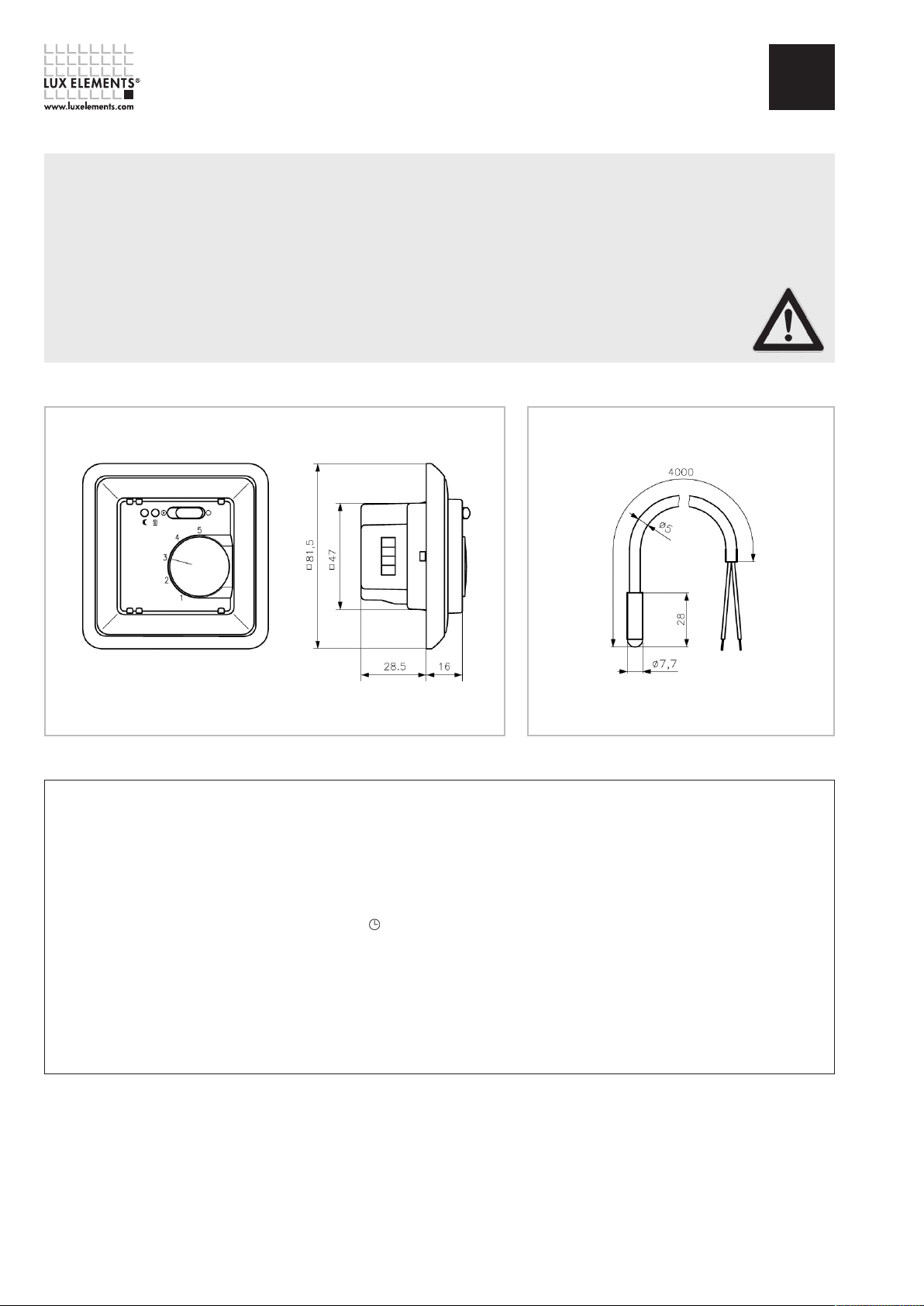
Dimensions in mm
Dimensions SensorDimensions Controller
n
Sensor breakdown detection: heating is turned off
n
Indicators: red LED for ‘heating‘ and green LED
for ‘night decrease mode‘
n
Terminal screws: 0,5 – 2,5 mm
n
Mounting: in an UP box (Ø 55 mm)
n
Degree of protection: IP 30
n
Protection class: II (after corresponding installation)
n
Ambient temperature: 0 ... 40 °C
n
Storage temperature: -20 ... +70 °C
n
Radio interference suppression: acc. to EN 50081-1 and EN 50082-1
2
Dimensions in mm
VDE = German Electrical Engineering Association
Page 2 – LUX ELEMENTS®-CONCEPT-BA-EH ZA
Page 3
LUX ELEMENTS®-CONCEPT-BA-EH ZA
Electronic temperature controller without timer ( 12 A, 230 V AC)
LUX ELEMENTS®-CONCEPT-BA-EH ZB see page 4 / LUX ELEMENTS®-CONCEPT-BA-EH ZC see page 7
ZA
Area of application / functional method
Application example for the electric bench heating: The control variable is the bench temperature.
This is measured by means of the remote sensor at the heating mat level. The appliance comprises
the control module for setting the desired temperature and a temperature sensor which measures
the temperature and communicates the measured value to the control module
.
Functioning
The controller measures the temperature by means of a remote sensor which is placed inside
the building component. In case the temperature adjusted at the set value knob is underrun,
the contact with the heating is closed down (scale 1 ... 5 corresponds to ca. 10 ... 50 °C
temperature). The active state of the heating system is indicated by the red lamp. The heating
system can be deactivated with the switch. When connecting the phase to the terminal ,
the controller decreases the adjusted set value by approx. 5K. The green lamp indicates the
active state of this energy saving mode.
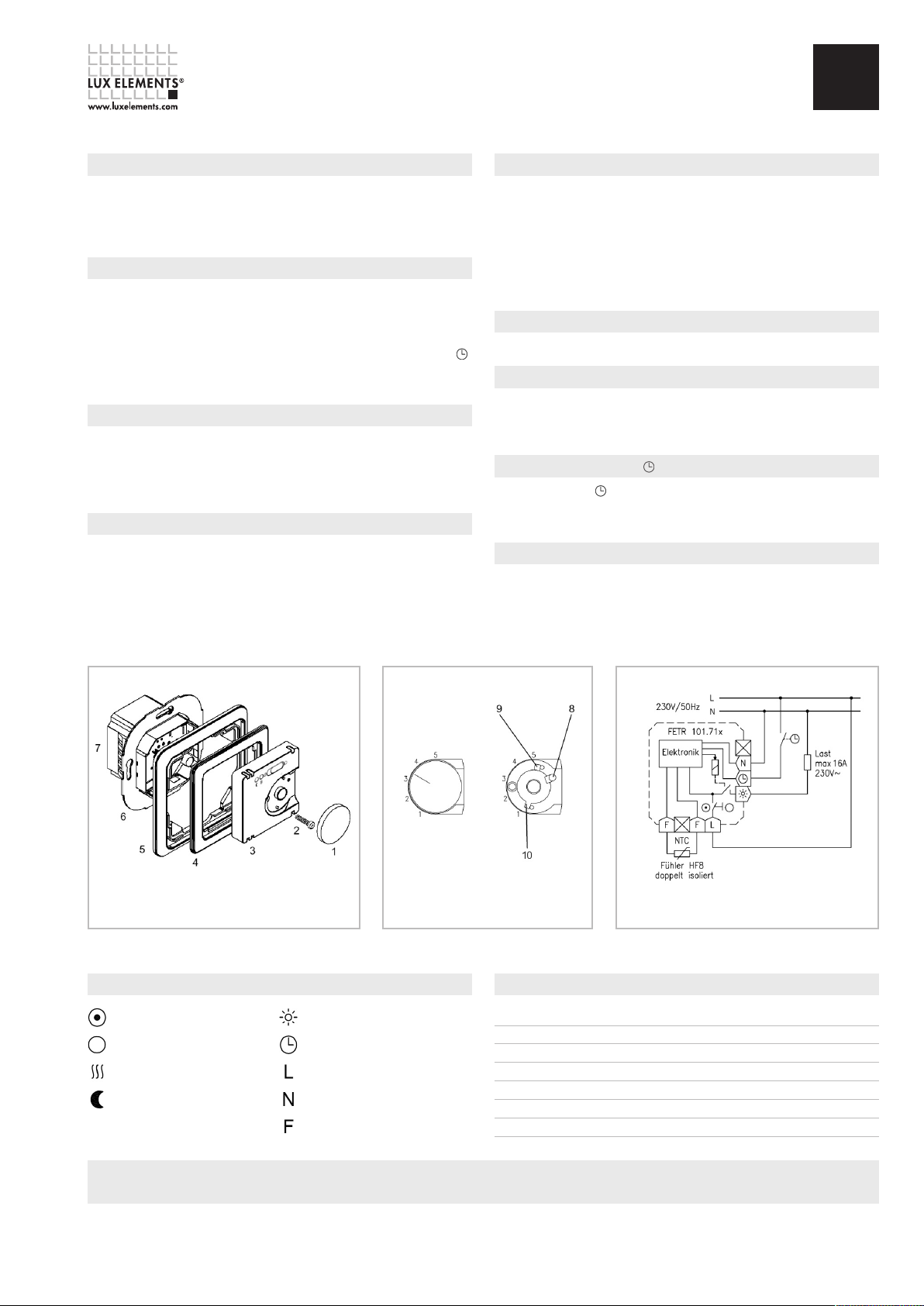
Opening the controller
·Lift out the thumb wheel (1) carefully using a screw driver
·Unscrew the fixing screw (2)
·Remove controller cover (3)
·Take off intermediate frame (4) and switch frame (5)
Installation controller
Caution, switch off mains voltage at all poles before installation!
·Electric connection according to ‘schematic diagram‘ with screw terminals
·Cross section of solid wire is load-dependant 1,5 ... 2,5 mm
·No protective conductor
·Install controller (7) in the flush-mounted box on the wall by means of a support ring (6)
and screws.
2
Installation sensor
·Between heating loops without contact
·Sensor lead inside protective tube
·Parallel laying with power cord prohibited
·Extension up to 50 m with 0.5 mm
·In the event of a fault or false connection, mains voltage may be present on the sensor.
Therefore, the sensor is double insulated according to EN 60730-2-1. Extension is only
permitted, using double insulation according to EN 60730-2-1.
2
(flexible conductors with cable end sleeve)
Close down device
·Close down of the device is effected in reverse order to opening.
Limitation of the setting range
·Remove pin (8)
·Turn red pin (9) for maximum temperature and blue pin for minimum temperature
·For fixation of the limits, plug-in the pin (8)
Connection of night decrease
If connected to terminal , night decrease is activated. This can be effected e.g. by a timer
or a watch regulator. (Caution! Two supplies) – if working at connector, the night decrease
is to be turned off as well.
Accessories
The controller is completely supplied with 4 m sensor sleeve (order designation HF-8/4-K2).
Explanation of symbols
Control ON (red)
Control OFF
Heating ON
Night decrease ON (green)
Limitation of the setting range Connection diagramMounting controller
Sensor characteristic curve
Heating connection
Connection Temperature decrease
Phase connection
Neutral conductor connection
Sensor connection
Temperature [°C] Resistance [k-Ohm] U [V]
10 3,66 2,49
20 2,43 2,22
25 2,00 2,08
30 1,65 1,92
40 1,15 1,63
50 0,82 1,35
Please refer to our data sheets. Valid data sheets and test certificates can be downloaded from www.luxelements.com.
LUX ELEMENTS®-CONCEPT-BA-EH ZA – Page 3
Page 4
LUX ELEMENTS®-CONCEPT-BA-EH ZB
Electronic temperature controller with timer (12A, 230 V AC)
®
LUX ELEMENTS
IMPORTANT NOTE
CAUTION: · Work on the 230 V mains supply may only be carried out by a qualified electrician.
· The national (Germany: VDE) and local electricity supply company safety regulations must be complied with when connecting the appliance.
CAUTION: · In the event of a fault, mains voltage may be present on the sensor cable (see fig. 1). Connecting cables must be straight and the insulation stripped by about 6 mm.
· The sensor cable must be laid in a separate protective pipe and must not be laid together with cables that conduct mains voltage.
CAUTION: · Type of protection IP 30 = no protection against penetrating water!
· The controller must be protected from moisture and water vapour (relative air moisture < 60%).
Please refer to our data sheets. Valid data sheets and test certificates can be downloaded from www.luxelements.com.
-CONCEPT-BA-EH ZA see page 2 / LUX ELEMENTS®-CONCEPT-BA-EH ZC see page 7
ZB
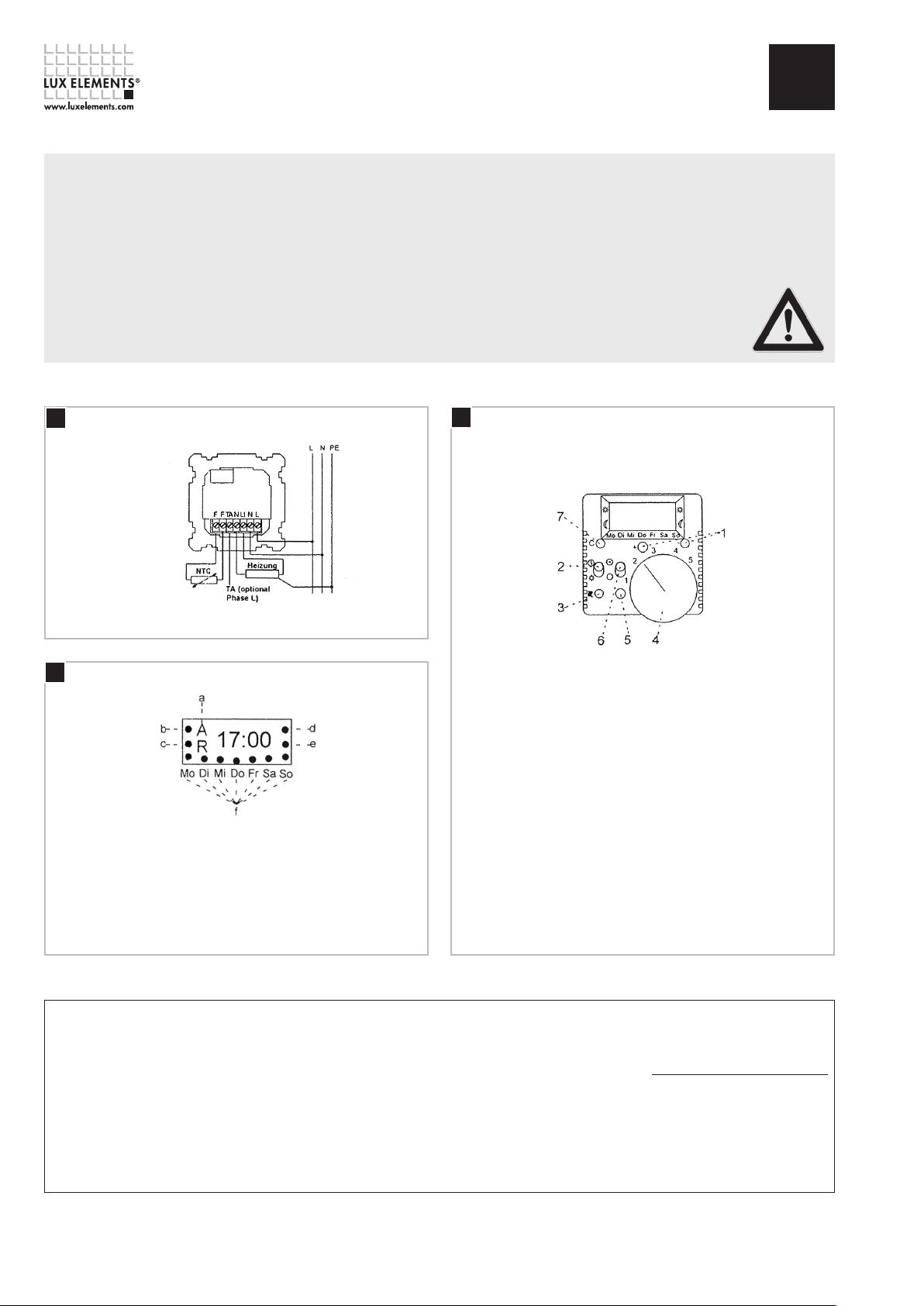
1
Temperature controller connection Overview of appliance (operating controls)
3
Display indications
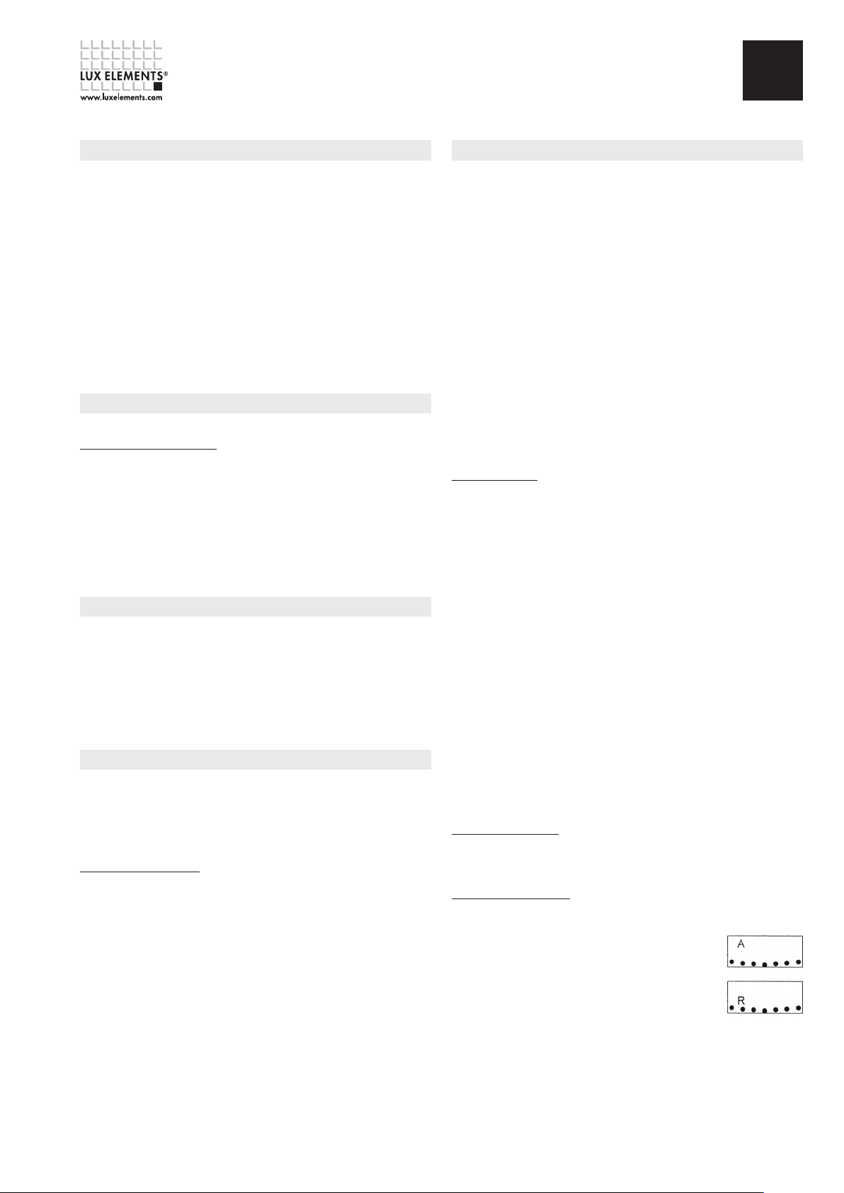
a. Day groups: A = weekdays, R = rest days (Sat & Sun)
b. 1st heating period
c. 1st temperature reduction period
d. 2nd heating period
e. 2nd temperature reduction period
f. Days of the week: Mon to Sun (from left to right)
2
Key to figure 2
1. ‘+’ and ‘-’ buttons = function: changing the setting variables
2. Sliding switch (‘party switch’) = function:
changing between timer programme and continuous operation
3. LED display = function: heating ON / OFF
4. Thumbwheel = function: temperature setting
5. RESET button = function: deleting time and day; heating
and temperature reduction periods remain unchanged
6. Sliding switc
5
. ‘C’ button = function: program sequence
NOTE: The factory setting is restored by pressing buttons ‘C’ (item 7),
‘+’ and ‘-’ (item 1) simultaneously.
h = function: heating ON / OFF
TECHNICAL DATA
n
Mains voltage:
230 V ⬃± 10 %, 50 Hz
n
Switching current for 6025:
approx. 16 A = 1, switching power 3,6 KW
n
Switching temperature difference: 0,7 K
Page 4 – LUX ELEMENTS®-CONCEPT-BA-EH ZB
n
Temperature sensor:
NTC (according to DIN 44574), length 4 m
n
Ambient temperature:
-10 to + 40 °C
n
Connecting cables: max. 2,5 mm
2
n
Sensor characteristic curve:
Temperature [°C] Resistance [k-Ohm]
10 3,66
20 2,43
30 1,66
40 1,15
50 0,82
Page 5
LUX ELEMENTS®-CONCEPT-BA-EH ZB
Electronic temperature controller with timer (12A, 230 V AC)
LUX ELEMENTS®-CONCEPT-BA-EH ZA see page 2 / LUX ELEMENTS®-CONCEPT-BA-EH ZC see page 7
ZB
Area of application / functional method
The electronic temperature controller with timer serves for the control of temperature. The appliance
comprises the control module for setting the desired temperature and a temperature sensor,
which measures the temperature and communicates the measured value to the control module.
Application example for the electric bench heating: the control variable is the b
This is measured by means of the remote sensor at the heating mat level.
The integrated digital clock enables switching from heating to reduced temperature twice per
day, i.e. up to two different heating and reduced temperature phases can be specified differently
for weekdays (e.g. Mon to Fri) and rest days (e.g. Sat, Sun). The assignment to weekdays/rest
days can be changed.
ing switch ‘On / Off’ (fig. 2, item 6) isolates one pole of the heating from the mains
The slid
supply and switches off the appliance completely except for the clock.
The sliding switch ’Timer programme/continuous operation’ (fig. 2, item 2) enables switching
from timer-controlled heating regulation to heating control without timer (e.g. continuous
operation for a party).
ench temperature.
Mounting
CAUTION! Switch off the mains voltage!
Mounting the temperature controller:
flush-mounted boxes x 55 mm (in accordance with DIN 49073, part 1). If additional intermediate
terminals are used, we recommend the use of a deeper switch boxes.
· Lift out the thumbwheel carefully using a screwdriver
· After unscrewing the fixing screw, remove the controller cover
· Refer to fig. 1 when connecting
· CAUTION! Position the support ring
the self-tapping flush-mounted box screw
· Then place the frame and the cover on the flush-mounted insert and screw it tight
· Finally push the thumbwheel (with the groove positioned correctly) onto the appliance
both controllers are installed in commercially available
on the wall and mount the controller in the box using
Limiting the temperature range
The temperature setting range of the controller can be mechanically limited by reducing the
angle of rotation of the thumbwheel. To do this, proceed as follows:
· Lever up the thumbwheel (see fig. 2, item 3) carefully using a screwdriver
· Pull out the stop pin (of the range limiter on the appliance cover) with the aid of a pair of
long-nosed pliers
· Turn the small gear wheel in order to limit the movement of the thumbwheel
· To fix the thumbwheel again, proceed in the reverse order
· The mains voltage need not be switched off to limit the temperature range
Commissioning
The controller is factory-programmed as follows:
- 6:00 to 21:59: heating period, temperature selection via thumbwheel
- 22:00 to 5:59: reduced temperature of 15 °C
- Weekdays (Mon to Fri)
- Rest days (Sat, Sun)
Commissioning/setting the time
If you wish to use the factory-set values, proceed as follows to commission the appliance:
· Press button ‘C’ and set the time using the buttons ‘+’ and ‘-’.
· The time will be shown on the display.
Press button ‘C’ again and set the day of the week using the buttons ‘+’ and ‘-’.
· The day of the week will be displayed (see fig. 3, item f)
The controller switches automatically to operating mode after 3 m
reviously (time and day of the week) will thereby be adopted. Commissioning is now complete
p
and the appliance is operating.
NOTE: To adapt the controller to your individual requirements, please proceed as described in
the chapter ‘Programming’.
inutes. The values entered
Programming
If you wish to use other values (see also chapter ‘Commissioning’), the controllers are programmed
in the following order (factory settings in brackets):
- Reduced temperature (15 °C)
for weekdays:
- Start of 1st heating period (06:00)
- Start of 1st reduced temperature period (22:00)
- Start of 2nd heating period (00:00)
- Start of 2nd reduced temperature period (00:00)
for rest days:
- Start of 1s
- Start of 1st reduced temperature period (22:00)
- Start of 2nd heating period (00:00)
- Start of 2nd reduced temperature period (00:00)
The following steps are necessary in order to program each individual category:
·Press button ‘C’ and set the new value using the buttons ‘+’ and ‘-’.
·The values/indications will be updated on the display.
·Press button ‘C’ to end programming
N
the ‘current’ time again automatically after three minutes and will continue to work with the
values entered.
Programming example:
In the following example, the reduced temperature and the first heating and first reduced
temperature period for the weekdays are to be changed; the settings for the rest days should
remain unchanged.
Proceed as follows to programme:
·Press button ‘C’
- the current time will be displayed
·Press button ‘C’ again
- the current day of the week will be displayed
·Press button ‘C’ again
·Set the reduced tempe
- the new reduced temperature, e.g. 15 °C, is displayed
·Press button ‘C’ again
- the symbol A and the weekdays are displayed
·Set the first heating period using ‘+’ and ‘-’
- the start of the new first heating period, e.g. 7:00, is displayed
·Press button ‘C’ again
- the symbol A and the weekdays are displayed
·Set the first reduced temperature period using ‘+’ and ‘-’
- the
·Press button ‘C’ again
·Do not make any further entries
·The controller works with the new values after 3 minutes
Restoring the factory setting:
The simplest way to restore the above-mentioned factory setting is as follows:
·Press the buttons ‘C’, ‘+’ and ‘-’ simultaneously (see fig. 2)
·After that please update the time and day of the week (see chapter ‘Commissioning’).
Definition of work and rest days
The factory-defined weekdays (Mon to Fri) and rest days (Sat, Sun) can be changed as
follows:
·Press the buttons ‘+’ and ‘-’ simultaneously
·Then press button ‘C’
- the symbols for all days of the week appear on the display
- the symbol ‘A’ and ‘Mon’ flash
·Press button ‘+’ to turn Mon into a rest day
- the symbol ‘A’ disappears and the symbol ‘R’ appears
- the symbol ‘Mon’ flashes
·Press button ‘C’ t
·Press buttons ‘+’ and ‘-’ simultaneously to return to normal controller mode
You can switch between ‘R = Rest days’ and ‘A = Workdays’ using buttons ‘+’ and ‘-’.
Confirm each change by pressing button ‘C’.
t heating period (06:00)
: P
rogramming can be ended at any time by pressing button ‘C’. The controller will display
OTE
rature using ‘+’ and ‘-’
start of the new first reduced temperature period, e.g. 22:00, is displayed
o activate the next day (Tue) and proceed in the same way
LUX ELEMENTS®-CONCEPT-BA-EH ZB – Page 5
Page 6
LUX ELEMENTS®-CONCEPT-BA-EH ZB
Electronic temperature controller with timer (12A, 230 V AC)
LUX ELEMENTS®-CONCEPT-BA-EH ZA see page 2 / LUX ELEMENTS®-CONCEPT-BA-EH ZC see page 7
ZB
Operation
Continuous operation
If you do not wish your heating to be controlled by the timer, switch the left sliding switch (fig. 2,
item 2) downwards to ‘Continuous operation’ (sun symbol). (The clock programming is not
affected by this. After switching back to the ‘Timer programme’ position, the controller continues
to work in accordance with the defined heating period pattern).
Switching off the heating
If you wish to specifically turn off your heating, please switch the right sliding switch (fig. 2,
item 2) downwards (circle symbol).
Switching on the heating
If you wish to specifically turn on your heating, please switch the right sliding switch (fig. 2,
item 2) upwards (circle/dot symbol).
NOTE: the LED display lights up only when heating is required.
Power cut
In the event of a power cut or an open or short circuit of the sensor cable, the heating is switched
off.
The display (fig. 2) starts to flash. The time will be displayed for approx. two more days.
The programmed values are retained, however. Reset the time if necessary (see chapter
‘Commissioning’).
CAUTION! In the event of a fault, mains voltage may be present on the sensor cable.
Please refer to our data sheets. Valid data sheets and test certificates can be downloaded from www.luxelements.com
Troubleshooting
Diagnosis Possible cause/remedy
Heating doesn’t work - Switch on/check the mains voltage
- Check the heating
- Check the sensor cable
- Check the set temperature
- Check the reduced temperature
Display is blank - Switch on/check the mains voltage
- Check the appliance
Controller switches too early/late to - Check work and rest day settings
heating/reduced temperature period - Press RESET, then carry out settings again
LED flashes - Sensor is not connected or is defective
Page 6 – LUX ELEMENTS®-CONCEPT-BA-EH ZB
Page 7
LUX ELEMENTS®-CONCEPT-BA-EH ZC
electronic temperature controller for mounting in distribution cabinet
LUX ELEMENTS®-CONCEPT-BA-EH ZA see page 2 / LUX ELEMENTS®-CONCEPT-BA-EH ZB see page 4
ZC
IMPORTANT NOTE
CAUTION: Work on the 230 V mains supply may only be carried out by a qualified
electrician. The national (Germany: VDE) and local electricity supply company
safety regulations must be complied with when connecting the appliance.
CAUTION: In the event of a fault, mains voltage may be present on the sensor
cable. Connecting cables must be straight and the insulation stripped by about 6 mm.
CA
UTION: Type of protection IP 20 = no protection against penetrating water!
The controller must be protected from moisture and water vapour (relative air
moisture < 60%).
Please refer to our data sheets. Valid data sheets and test certificates can
be downloaded from www.luxelements.com
General
The currently valid VDE and DIN regulations as well as the technical connection conditions (TAB)
from the local electricity supply company must be observed during the installation of control
units! Resistance measuring may only be carried out with a resistance tester. Insulation
measurements may not be performed.
Fitting the measuring probe
The standard probes have a length of 3 m. Get in touch with us prior if you are laying the probe
lines directly near power cables with frequent switching operations. Probe lines may be extended
by a maximum of 500 m.
A semiconductor (NTC) is used as a temperature probe; it is cast integral inside a 5 x 50 mm
protective sleeve and is connected using a flexible connecting lead 2 x 0.75 mm
silicon sheath. Temperature probes with silicone leads should be used for ambient temperature
exceeding 70 °C. These are connected either directly on the control unit or via a terminal box.
The location in which the temperature probe is mounted depends on the type of heating and the
task of the electric heater. The rule that generally applies is that the probe should be mounted
in the place that is most suitable for acquiring the reference temperature (system temperature).
For example, if the bench heating is to provide temperature equalisation for the surface, the
temperature probe should be installed in lines near the surface. In the case of pipe accompanying
heaters using a heating loop or between the heating circuits, these are offset by about 90 °C
with a simple parallel layout. The temperature probe is situated directly on the tube underneath
the
insulation.
If limitation transfer elements are used for pipe accompanying heaters, then the corresponding
temperature probe is fitted in parallel about 1 m from the heating line.
Fitting the measuring probe
All the measurements must always be taken while the probe lines are disconnected.
2
with a PVC or
57
86
48
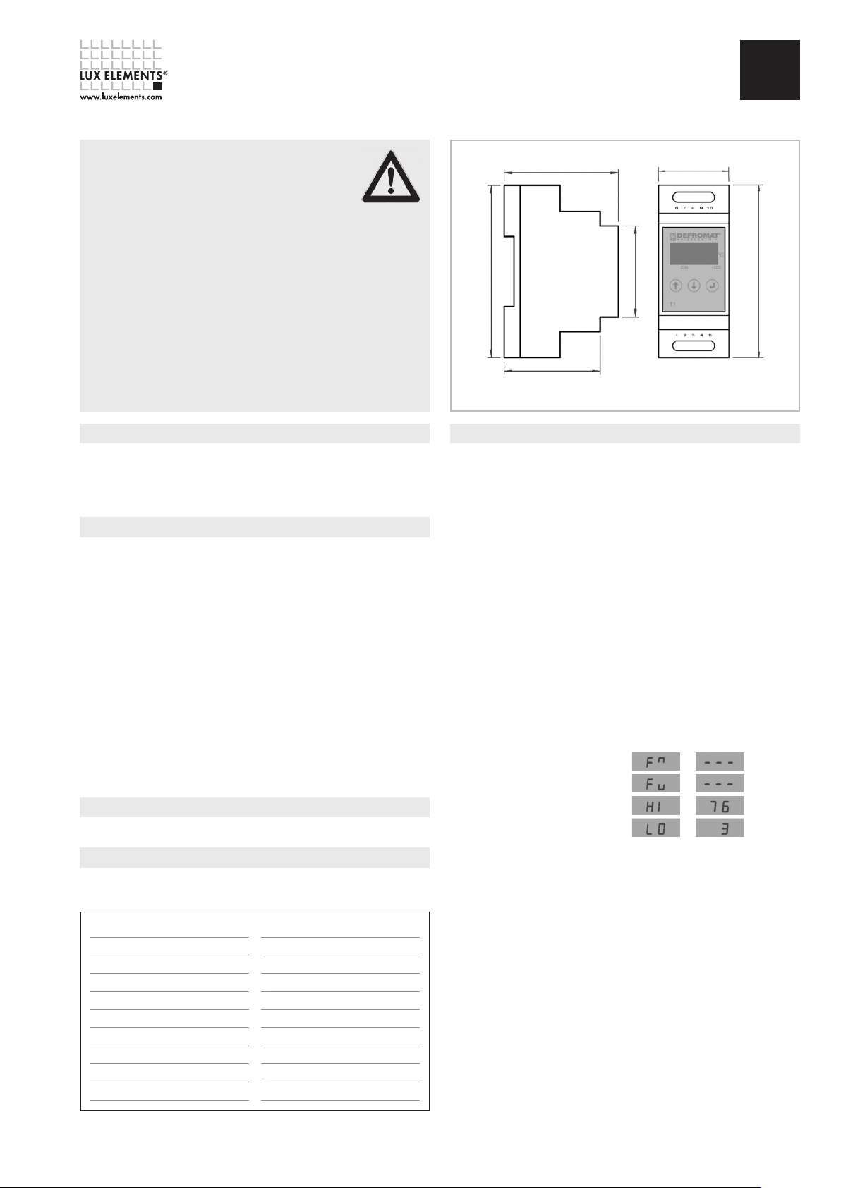
Housing dimensions
46
35
86
Commissioning
The functionability of the entire control equipment and control system is tested after the control
equipment and control system has been assembled and the installation of the control equipment
and the measuring probe(s). The temperature is cooled down using cooling spray to below the
required switching point or is carefully warmed up to the switch off point. That way, it is possible
to control at what point the heating switches on using a clip-on ammeter or voltmeter. If you
only want to test the function of the control equipment, the temperature can be simulated with
a corresponding resistance between terminal 9 and 10.
The control equipment is designed in such a way that there is a potential-free relay output
available (connection terminals 4 and 5). Switching is possible over the relay on the control
equipment up to a heating capacity of 1kW approx.
The control equipment is equipped with a potential-free fault alarm output. This is especially
intended for the mandatory monitoring of the temperature probe if sprinkler systems are being
heated. This can also be used to monitor whether separate threshold values are exceeded or fall
short.
The fault alarm output is closed when the control equipment is in an ON state between
connections 6 and 7; in the event of a fault, the relay opens and the type of fault and the
measured temperature are displayed alternately.
F
ault Display (alternating)
Missing power supply
Probe breakdown in temperature probe
Probe short in temperature probe
HI value exceeded
LO value not attained
None
Dimensions in mm
Test values on the temperature probe
The temperature probe that is used is characterised by a nonlinear, negative temperature resistance
curve. Use the following table to check this:
Temperature [°C] Resistance [k-Ohm]
-10 16,599
-5 12,699
0 9,795
5 7,617
10 5,970
15 4,713
20 3,747
25 3,000
30 2,417
Temperature [°C] Resistance [k-Ohm]
35 1,959
40 1,598
45 1,311
50 1,081
60 0,746
70 0,526
80 0,377
90 0,275
100 0,204
Repeat the commissioning procedure annual when preparing system for operation.
LUX ELEMENTS®-CONCEPT-BA-EH ZC – Page 7
Page 8
LUX ELEMENTS®-CONCEPT-BA-EH ZC
electronic temperature controller for mounting in distribution cabinet
LUX ELEMENTS®-CONCEPT-BA-EH ZA see page 2 / LUX ELEMENTS®-CONCEPT-BA-EH ZB see page 4
Displays and settings
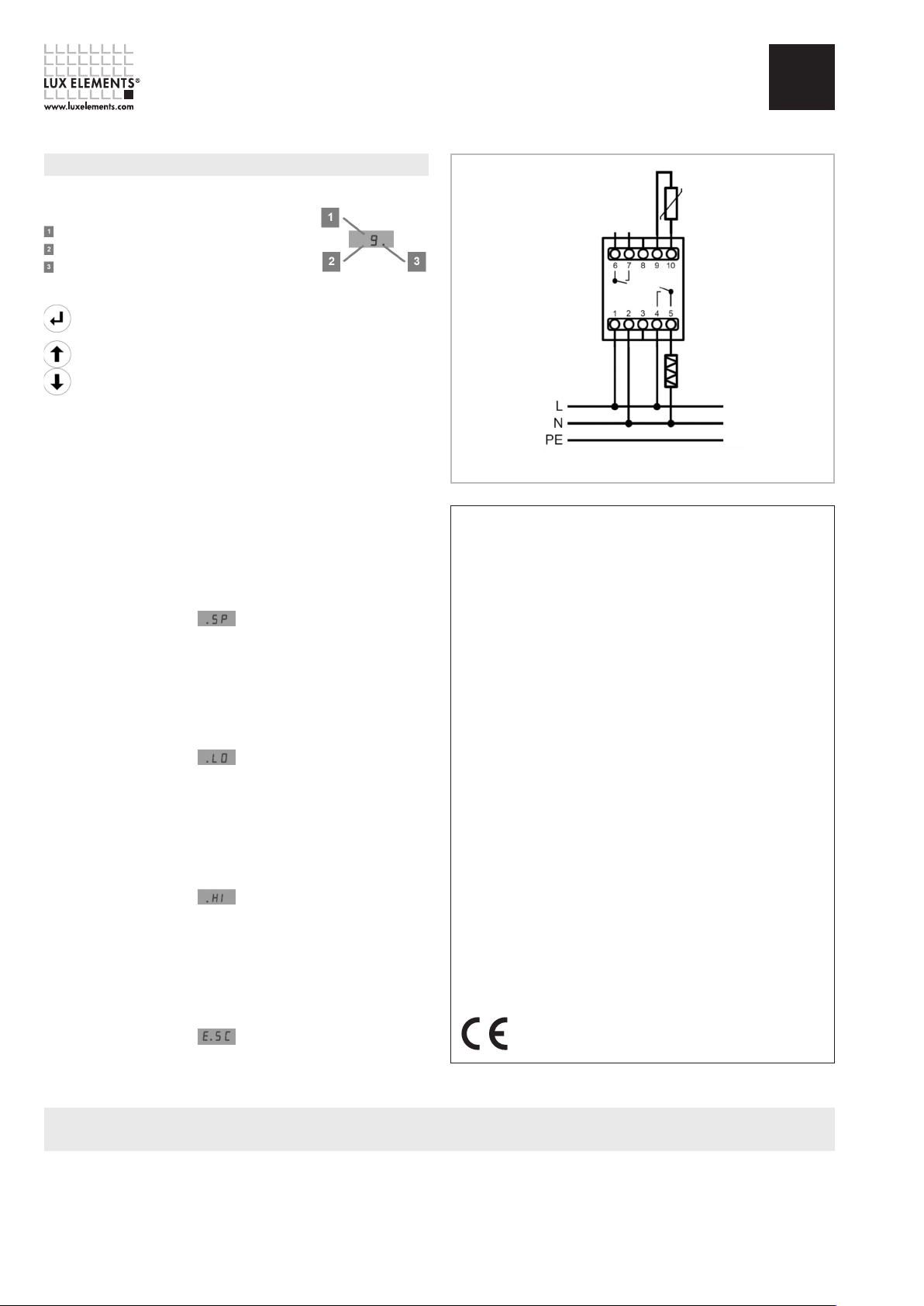
All the readings are shown on a three digit LED display
Standard display:
Temperature reading in °C
Edit (Decimal point on for first digit = Menu; off here)
Heating (Decimal point for last digit on = Heating on)
The following three keys are used for operation:
‘ENTER‘ key to leave standard display
and to change setpoints (Menu)
‘UP‘ and ‘DOWN‘ keys to call up
individual required se
(Scroll forwards /backwards, adjust plus /minus)
The control equipment is delivered with a basic setting The values for the temperature switching
point equal +3 °C, and OFF is set for the HI and LO switching point.
These switching points can be altered for every specific system using the menu. Restoring
the standard display is performed using the menu item ESC (confirm with ENTER) or occurs
automatically after approximately 30 seconds.
The menu is addressed with ENTER; the required menu item is selected with UP and DOWN.
To change the selected value, ENTER has to be pressed again; the value that is being changed
appears then. UP and DOWN are used to change the value (the longer you press the button, the
faster the values change). ENTER must be pressed to transfer the value that may have been
changed.
Menu Item Switching Point
Display and temper
Display
Setting range
Increments 1K
Basic setting 3 °C
Menu Item Alarm in case of temperature shortfall
A threshold value, at which the fault alarm output is opened in the case of a shortfall, can be set
in this menu.
Display
Setting range OFF, -30 °C ... SP-1K
Increments 1K
Basic setting OFF
Menu Item Alarm in case of excessive t
A threshold value, at which the fault alarm output is opened in the event temperature is exceeded,
can be set in this menu.
Display
Setting range
Increments 1K
Basic position OFF
Menu item Escape
This display is confirmed with ENTER, then you reach the standard display. This also occurs
automatically without pressing the button after approximately 30 seconds.
Display
ature setting at which heating switches if value falls short.
tpoints and actual values
-30 °C ... 110 °C
emperature
OFF, SP+1K ... 110 °C
ZC
Fault alarm
max. 5A
Connection diagram
TECHNICAL DATA
n
Type T1
n
Voltage supply 230V AC 50/60 Hz
n
Power consumption 5 VA (max.)
n
Ambient temperature -10 °C ... + 50 °C
n
Storage temperature - 40 °C ... + 80 °C
n
Measuring range -40 °C ... +120 °C
n
Output Make contact relay
250 VAC/150 VDC, 5A cos φ=1
n
Fault alarm output Make contact relay
250 VAC/150 VDC, 5A cos φ=1
n
Accuracy +/- 1K (-30 °C ... +100 °C)
+/- 2K (< -30 °C ; > +100 °C)
n
Weight about160 g
n
Connections Capacity 0,5 ... 2,5 mm²
n
Dimensions (approx.) W: 35 mm, H: 86 mm, D: 57 mm
n
Class of protection Protection class II
n
Type of protection IP 20
n
Assembly Snap on 35 mm DIN-Rail
Conformity in accordance with EMC Directive 2004/108/EEC
as well as Low Voltage Directive 2006/95/EU.
Temperature
probe
Heater
Please refer to our data sheets. Valid data sheets and test certificates can be downloaded from www.luxelements.com.
Page 8 – LUX ELEMENTS®-CONCEPT-BA-EH ZC
 Loading...