

Page 1
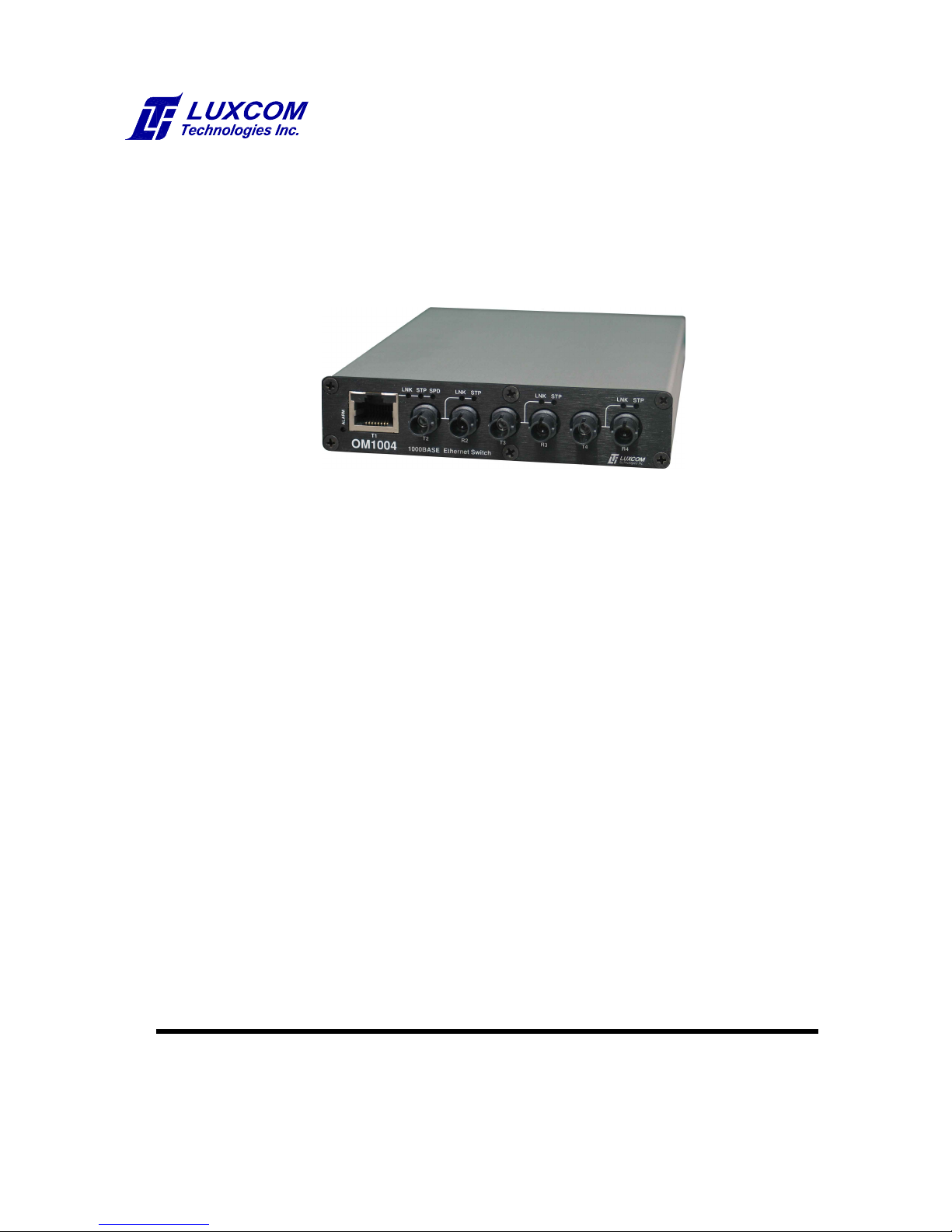
OM1004
Ethernet Switch
Three 1000BASE-X optical ports
One 10/100/1000BASE-T port
With Rapid Spanning Tree
OPERATING MANUAL
102 WALGREEN ROAD, OTTAWA, ONTARIO, K0A 1L0
Telephone (613) 831-7777 Fax (613) 831-7778
REV. 2.5
April 26, 2013
www. luxcom.com
email: [email protected]
Page 2

Table of Contents
Description........................................................................................................................1
Indicators..........................................................................................................................1
Dip Switches.....................................................................................................................2
Rapid Spanning Tree Protocol (RSTP)..........................................................................3
Configuration Interface...................................................................................................4
OM1004 Main Menu..........................................................................................................4
The main menu is shown below.....................................................................................4
Bridge RSTP Menu...........................................................................................................6
Software Menu..................................................................................................................7
Specifications*.................................................................................................................9
Ordering Information.....................................................................................................10
Certification....................................................................................................................10
Warranty..........................................................................................................................10
Page 3

Manual Revision History
Revision 1.0 Initial release
Revision 2.0 new format
Revision 2.1
Revision 2.2
Revision 2.3 Revise ALARM LED description
Revision 2.4 Update spec. for power supply
Revision 2.5 auxiliary power supply cube not supplied.
I
Page 4

Description
The OM1004 Ethernet switch has three 1000BASE-X optical ports and one 10/100/1000BASE-T
electrical port. Rapid Spanning Tree (RSTP) allows redundant connections between nodes. A
dip switch allows plug and play RSTP, while the serial console port allows for an RSTP
configuration tailored to specific needs. Optics for multimode, singlemode, and single fiber
applications are available. A universal AC power supply is built in, while an auxiliary 5V DC input
from an external power cube (not supplied) allows for power source redundancy. The OM1004
is enclosed in a rugged metal case for low radiated and conducted emissions. It does not
support jumbo packets.
Features
Description
Indicators
LNK Link On when a bidirectional optical or electrical LINK has been
STP Spanning Tree Green when the port is forwarding packets in RSTP mode.
RSTP algorithm allows redundant links
One 10/100/1000BASE-T electrical port
Three 1000BASE-X optical ports
Plug and play operation
Redundant power supply inputs
established with a remote Ethernet port.
Flashing when data is being transmitted or received.
Yellow when the port is blocking packets (is a standby link).
Note that only one end of a blocked link shows the blocking state;
however the remote link indicator will not flash which indicates it is
not passing data, and is therefore a backup link.
Green/Yellow when the port is in the transitory learning state.
Off when the port is not in RSTP mode.
Single or multimode fiber option
Single bidirectional fiber option
SC or ST optical connectors
Temperature range -10°C to 70°C
Distances up to 100 km
5 Year warranty
SPD Speed Green when electrical port is 1000BASE-T.
ALARM The switches on the back of the OM1004 control this indicator. It is
on when the link for a required port is off, or no link is present on
any port. When a port is required for proper network operation, the
corresponding switch should be up. The front panel Alarm indicator
will then come on (red) when a required link fails. This gives a
visual indication of link failure. This is especially important in a
redundant fiber configuration where the failure would not cause a
data transfer failure, and would hence go unnoticed. If the
electrical port is connected to a computer which is turned off at the
end of the day, switch five which controls that port should be down
(off) to avoid unnecessary alarms.
1
Page 5

Dip Switches
1 RSTP Up enables Rapid Spanning Tree Protocol (RSTP).
2 Mode Up (software) allows the RSTP to be configured using the Serial
Down (hardware) sets the RSTP to function in its default settings.
3 Unused
4 Unused
5 Port alarm 1 Up if port 1 (electrical port) is a required port. See Alarm in the
6 Port alarm 2 Up if port 2 (optical port) is a required port. See Alarm in the
7 Port alarm 3 Up if port 3 (optical port) is a required port. See Alarm in the
8 Port alarm 4 Up if port 4 (optical port) is a required port. See Alarm in the
Dip Switches
See the Rapid Spanning Tree section.
Configuration Interface.
Indicator section.
Indicator section.
Indicator section.
Indicator section.
2
Page 6
Rapid Spanning Tree Protocol (RSTP)
1
2 3
1
2
3
1
2 3
A
B
C
No Spanning Tree
1
2 3
1
2 3
1
2 3
1
2
3
4
5 6
D
A
B
C
When a connection between Ethernet switches exists, making a second connection
directly or indirectly (through a third switch) will disrupt the Ethernet network unless the
Rapid Spanning Tree Protocol (RSTP) is active. The RSTP will disable all redundant paths,
and transmit data only over the preferred path; if the preferred path fails, the next port on
the priority list will become enabled. When the OM1004 is in RSTP mode, and Hardware
(default) mode, and has redundant paths, the data path with the lowest cost (highest
throughput) becomes active, and the other path(s) are blocked. When alternate paths have
the same cost, the lowest number port (including the RJ45 port) is the preferred path.
Alternately the serial Configuration Port on the OM1004 can be used to set the priority of
the ports (SW2 up), however this is best avoided unless the user is familiar with RSTP.
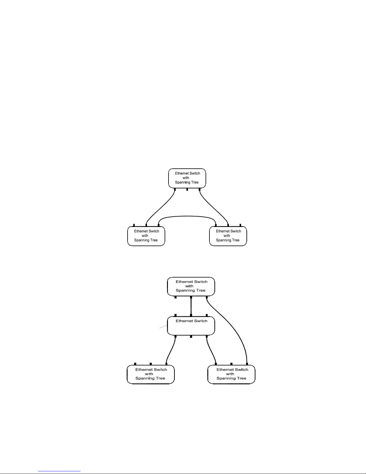
The following figure shows an an example of an acceptable OM1004 spanning tree
configuration when in the default plug-and-play mode. Note that each port connects to
one other spanning tree port.
Rapid Spanning Tree Protocol (RSTP)
The following figure shows an unacceptable spanning tree configuration when in the
default plug-and-play mode. Note that port 2 of switch A connects to switch B and C.
If it is desired to use the above topology, the OM1004 should be set for software
configuration, and configuration menu item e Set port admin p2p MAC should be set to
NO (the default of AUTO usually becomes YES). This will allow the above topology at the
expense of a longer recovery time when the topology changes.
3
Page 7

Importance of the Root Node
In RSTP, the root node is fundamental in determining the final topology of a network - i.e.
which redundant paths become blocked. RSTP first determines the root node, then the
other nodes determine the shortest and fastest path to that root node. Ideally the root node
connects directly to equipment (such as a server) which experiences the highest traffic
volume. The root node location cannot be controlled when all nodes are in the hardware
default settings; however in software configuration mode, the menu item 4 Set bridge
priority may be set to a low number (such as 0) which forces that node to be the root node.
The other nodes may be left in the hardware default mode.
Configuration Interface
This serial RS232 interface allows the user to configure the RSTP and monitor the
Ethernet statistics; its use is optional. The supplied cable must be connected between the
serial port of a PC and ths interface. A terminal emulation program must be used on the
PC. HyperTerminalTM which comes with the WindowsTM XP operating system is one
option.
To start HyperTerminalTM do the following:
Click on the START icon
Select Programs
Select Accessories
Select Communication
Select HyperTerminal
Rapid Spanning Tree Protocol (RSTP)
To configure HyperTerminalTM do the following:
Select File
Select properties
On drop-down called connect to
Select ..................direct to COM1
Select ..................configuration
Bits per Second . .= 38400
Data Bits..............= 8
Parity ...................= None
Stop Bits..............= 1
Flow control.........= Hardware
At this point pressing “enter” on the keyboard will bring up the OM1004 management
menu.
OM1004 Main Menu
The main menu is shown below.
OM1004 Main Menu
1 Ethernet menu
2 Bridge RSTP menu
3 Software menu
:>
1' selects the Ethernet menu, etc. Enter displays the current menu. In a sub-menu, Esc goes back
one menu level.
4
Page 8

The main menu is shown below.
Ethernet Menu
The Ethernet menu is shown below:
OM1004 Ethernet Menu
1 Show ethernet status
2 Show switch interface and port registers
3 Show switch global registers
4 Show port packet statistics
Esc Back
:>
This menu shows status and statistics for each port. The ports are plug and play, so there are no
configuration options. Ethernet menu item 1 shows the link status of all ports; items 2 and 3 are for
factory diagnostic use only; item 4 shows the traffic statistics for each port.
Here is a sample of the information available in this menu:
OM1004 Ethernet Menu
1 Show ethernet status
2 Show switch interface and port registers
3 Show switch global registers
4 Show port packet statistics
Esc Back
:> 1
Ethernet Status
Port 1 2 3 4
Switch Port P1 P4 P6 P5
Type Electrical Optical Optical Optical
Media Copper Fiber Fiber Fiber
Link Good Yes No No No
Auto-Negotiation Enabled Enabled Enabled Enabled
Speed 100BASE-TX 1000BASE-X 1000BASE-X 1000BASE-X
Duplex Full-Duplex Not available Not available Not available
MDI/MDI-X MDI NA NA NA
:> 4
Enter switch port (1 - 6): 1
Packet Statistics for Port P1 (cleared when read)
InGoodOctestsLo: 1686, InGoodOctestsHI: 0
InBadOctets: 0, OutFCSErr: 0
InUnicast: 0, Deferred: 0
InBroadcasts: 22, InMulticasts: 0
64Octets: 22, 65 to 127Octets: 8
128 to 256Octets: 0, 256 to 511Octets: 0
512 to 1023Octets: 0, 1024 to MaxOctets: 0
OutOctetsLo: 512, OutOctetsHi: 0
OutUnicast: 0, Excessive: 0
OutMultcasts: 8, OutBroadcasts: 0
Single: 0, OutPause: 0
InPause: 0, Multiple: 0
InUndersize: 0, InFragments: 0
InOversize: 0, InJabber: 0
InRXErr: 0, InFCSerr: 0
Collisions: 0, Late: 0
5
Page 9

Bridge RSTP Menu
The Bridge RSTP menu is shown below:
OM1004 Ethernet Bridge Menu
See IEEE Std 802.1D-2004 for variable descriptions
1 Show bridge status
2 Show port status
3 Set default configuration (reboot required)
4 Set bridge priority (BridgePriority)
5 Set bridge hello time (HelloTime)
6 Set bridge max age (MaxAge)
7 Set bridge forward delay (FwdDelay)
8 Set bridge protocol version (rstpVersion)
9 Set bridge transmit hold count (TxHoldCount)
a Set port priority (portPriority)
b Set port path cost (PortPathCost)
c Set port admin edge (AdminEdge)
d Set port auto edge (AutoEdge)
e Set port admin p2p MAC (adminPointToPointMAC)
f Port mode check
Esc Back
:>
Bridge RSTP Menu
This menu shows the status and configuration options for the Rapid Spanning Tree Protocol. It is
recommended that these parameters only be changed by someone with an understanding of IEEE
802.1D-2004. In most cases the default settings are adequate. The RSTP options are shown below.
The hardware /software default settings are shown in brackets to the right of each item.
1 Show bridge status Shows status which applies to all ports on the OM1004.
2 Show port status Shows status which applies to individual ports on the OM1004.
3 Set default configuration Restores the saved RSTP configuration to its default settings. Reboot
required.
4 Set bridge priority [32768] The number must be a multiple of 4096 between 0 and 61440.
A low number makes it more likely to be the RSTP root node.
5 Set bridge hello time [2] The interval in seconds when the root bridge broadcasts a packet with
topology information.
6 Set bridge max age [20] If another bridge in the RSTP does not send out a hello packet in this
time (in seconds), it is assumed to be dead.
7 Set bridge forward delay [1] The time in seconds for the bridge to be in the Learning state before
the Forwarding state is entered. This delay causes a new bridge on a
network to look at some traffic before participating.
8 Set bridge protocol version [2] 1 = old Spanning Tree Protocol, 2 = new Rapid Spanning Tree
Protocol.
9
Set bridge transmit hold count
[6] The transmit hold count.
a Set port priority [128] This number must be a multiple of 16 between 0 and 240. A low
number makes it more likely to be a forwarding port (as opposed to a
blocking port).
6
Page 10

Bridge RSTP Menu
b Set port path cost [0] Zero causes the path cost to be based on the link speed (automatic
mode). This number is 2x10¹³/data rate in bps. A low number means the
port is more likely to be chosen. The maximum number is 200 000 000.
c Set port admin edge [n] No causes the bridge detection state machine to initially assume
operEdge is false. Yes causes it to initially assume operEdge is true.
d Set port auto edge [n] No disables auto edge detection. Yes enables auto edge detection.
e Set port admin p2p MAC [auto] Yes causes the port to be treated as if it is connected to a “point-to
point” LAN. This allows the port to move into the forwarding state faster,
but there must be only one Ethernet RSTP bridge directly connected
to that port (e.g., the port cannot connect to an Ethernet switch with two
or more additional RSTP bridges connected). Auto causes
operPointToPointMAC to be set based on the duplex mode of the MAC
which is normally full duplex.
f Port mode check Causes the bridge to transmit RSTP BPDUs in order to test the
hypothesis that non RSTP bridges have been removed from the LAN
connected to the port, and if that is the case, the remaining bridges will
switch back to RSTP mode.
Software Menu
The software menu is shown below:
OM1004 Software Menu
1 Show stored files
2 Upload new BACKUP
3 Swap BACKUP and PRIMARY
4 Reset/Reprogram with new PRIMARY
Esc Back
:>
This menu allows new software files for the OM1004 to be uploaded with the Xmodem protocol and
installed. There are two stored files: PRIMARY and BACKUP. A new upload replaces the previous
BACKUP. The PRIMARY file is used for reprogramming the OM1004. BACKUP and PRIMARY can
be swapped with the `3' command.
A sample session is shown below:
OM1004 Software Menu
1 Show stored files
2 Upload new BACKUP
3 Swap BACKUP and PRIMARY
4 Reset/Reprogram with new PRIMARY
Esc Back
:> 1
PRIMARY MCU software file
Model: OM1004 Ethernet Switch
Card: Ethernet Card 1.1 Mar 24 2010 13:33:32
BACKUP MCU software file
Model: OM1004 Ethernet Switch
Card: Ethernet Card 1.0 Mar 5 2010 12:17:10
7
Page 11

:> 3
BACKUP file is now PRIMARY file
:> 2
Delete BACKUP file (y/n): y
Start Xmodem transfer (Send File)
CCCCCC
File upload successful
233984 bytes uploaded
:> 3
BACKUP file is now PRIMARY file
:> 4
Luxcom Technologies Inc.
OM1004 Ethernet Bridge BootLoader (Rev 1.0)
Erasing flash...
Writing flash...............................
Starting application...
Luxcom Technologies Inc.
OM1004 Ethernet Bridge Application (Rev. 1.1)
FreeRTOS.org V5.2.0 - Copyright (C) 2003-2009 Richard Barry.
lwip - Copyright (c) 2001-2003 Swedish Institute of Computer Science.
rstp - Copyright (c) 2007 EMC Corporation.
Software Menu
OM1004 Main Menu
1 Ethernet menu
2 Bridge RSTP menu
3 Software menu
:>
After the OM1004 requests the user to start the Xmodem transfer, the user must select the Xmodem
protocol and the upload file (e.g., using HyperTerminal's Transfer/Send File menu option). The
OM1004 send C's for thirty seconds. This is an indication to the terminal program to use the Xmodem
CRC protocol. After thirty seconds, the OM1004 switches to sending NAK characters every ten
seconds for another 100 seconds. This is an indication to the terminal program to use Xmodem
checksum mode. Thus, a user has approximately 130 seconds to select the upload file. Usually, it
doesn't matter whether the transfer occurs in CRC or checksum mode, however, some terminal
programs don't switch automatically from CRC to checksum mode. In that case, it may be necessary
to select the upload file in the first thirty seconds, or defer selecting the upload file until the OM1004
has switched to checksum mode.
8
Page 12

Specifications*
Optical
Specifications*
Model Light Fiber Optical Optical Optical Connectors
Source Size Output Sensitivity
1
Range
2
Minimum Maximum
SX 850 nm laser 50/125 µm -9 dBm -18 dBm 550 m SC or ST
SX 850 nm laser 62.5/125 µm -9 dBm -18 dBm 275 m SC or ST
LX 1310 nm laser 50/125 µm -9 dBm -20 dBm 1 km SC or ST
LX 1310 nm laser 62.5/125 µm -9 dBm -20 dBm 1 km SC or ST
LX 1310 nm laser 9/125 µm -9 dBm -20 dBm 10 km SC or ST
LXE 1310 nm laser 9/125 µm -3 dBm -23 dBm 40 km SC or ST
BU 1310 nm TX laser 9/125 µm -9 dBm -20 dBm 20 km SC or ST
BD 1550 nm TX laser 9/125 µm -9 dBm -20 dBm 20 km SC or ST
S8031550 nm laser 9/125 µm 0 dBm -23 dBm 80 km SC or ST
S10031550 nm laser 9/125 µm 0 dBm -32 dBm 100 km SC
Electrical
Data I/O levels ........................................................................ IEEE 802.3 compatible
Data I/O connector .................................................................. RJ-45
Auxiliary power input (cube not supplied) ............................... 4.8 - 5.2V DC
Mains powers supply .............................................................. 100 - 240V AC, 50-60 Hz
Power supply certification........................................................ UL, GS, CE
Power consumption ................................................................ < 4 Watts
General
Operating temperature ............................................................ -10°C to 70°C
Humidity (RH) ......................................................................... 10% to 95%
MTBF ...................................................................................... > 50,000 hours
Dimensions ............................................................................. 6.5 x 1.8 x 10 cm
Notes:
*Specifications are subject to change without notice.
1 Optical sensitivity measured at 10-10 BER.
2 The optical range values are for typical fiber.
3 Operating temperature range is 0°C to 70°C.
9
Page 13

Ordering Information
Ordering Information
OM1004-XX-XX
SC = Optical connectors
ST = Optical connectors
SX = 1000BASE-SX 850 nm multimode optics
LX = 1000BASE-LX 1310 nm single/multimode optics
LXE = 1000BASE-LX 1310 nm single/multimode optics
BU = 1000BASE-BX 1310 nm TX single-fiber bidirectional optics†
BD = 1000BASE-BX 1550 nm TX single-fiber bidirectional optics†
S80 = 1550 nm single-mode optics
S10 = 1550 nm single-mode optics
† The single-fiber models must be used as upstream/downstream pairs (one BU and one BD).
Mounting accessories for the OM1004 can be found at www.Luxcom.com
Certification
Luxcom Technologies Inc. certifies that this equipment met its published specification at
the time of shipment from the factory.
Warranty
This Luxcom product is warranted against defects in materials and workmanship for a
period of five years from the date of shipment. Luxcom will, at its option, repair or replace
products that prove to be defective during the warranty period provided they are returned to
Luxcom . Repairs necessitated by misuse of the product are not covered by this warranty.
NO OTHER WARRANTIES ARE EXPRESSED OR IMPLIED, INCLUDING, BUT NOT
LIMITED TO , THE IMPLIED WARRANTIES OF MERCHANTABILITY AND FITNESS
FOR A PARTICULAR PURPOSE. LUXCOM TECHNOLOGIES INC. IS NOT LIABLE
FOR CONSEQUENTIAL DAMAGES.
Repackaging For Shipment
Before returning the item, paperwork indicating the name, department, company and
telephone number of the sender, model and serial number of the product and a brief
description of the problem should be enclosed. As well, the sender must also request a
Return Authorization number from Luxcom Technologies Inc. See front cover for shipping
address.
10
 Loading...