

Page 1
WARRANTY & REPAIRS PART NUMBERS
Warranty
OM102P-XX-XX
This Luxcom Technologies Inc. product is war-
100BASE-TX to 100BASE-FX
ranted against defects in materials and workman-
Ethernet Media Converter
ST = ST optical connector
ship for a period of five years from the date of
SC = SC optical connector
with
shipment. Luxcom Technologies Inc. will, at its
LC = LC optical connector
48V PoE Output
option, repair or replace products which prove to
MM = 1300 multi-mode optics
be defective during the warranty period, provided
SM = 1300 singlemode optics
that they are returned to Luxcom Technologies Inc.
Repairs necessitated by misuse of the product are
Operating Manual
Monitor Port Cable ................................ 91-325-0
not covered by this warranty. No other warranties
are expressed or implied, including, but not limited
Mounting Plate ...................................... MB-1
to, the implied warranties of merchantability and
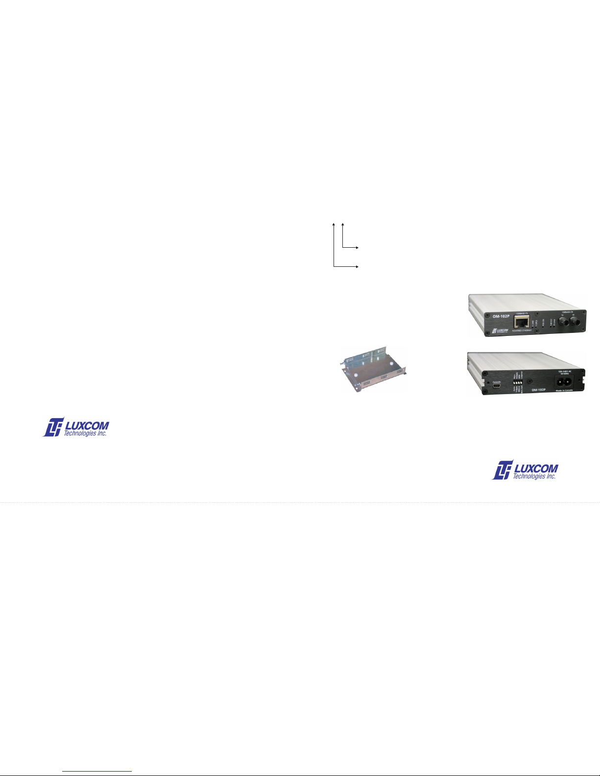
The OM102P may be desktop mounted, or it may be
fitness for a particular purpose. Luxcom
mounted in Luxcom's MB-1 mounting plate shown below.
Technologies Inc. is not liable for consequential
The modem slides into the plate and is held in place with two
damages.
thumb lock screws.
Claims
FRONT
If physical damage to the modem is found when
the product is received, notify the carrier and
Luxcom Technologies immediately. Luxcom
Technologies will arrange for repair or
replacement.
REAR
LUXCOM Technologies Inc.
102 Walgreen Rd., Ottawa, Ontario, Canada
K0A 1L0
www.luxcom.com
Certification
Tel: +1 (613) 831-7777
Fax: +1 (613) 831-7778
Luxcom Technologies Inc. certifies that this
REV. 1.7
modem met its published specification at the time
Sept. 06, 2011
email: [email protected]
of shipment from the factory.
Repacking For Shipment
If the modem needs to be shipped by commercial
transportation for service or repair, the sender
MB-1 Mounting Plate
must request a Return Material Authorization
number ( RMA ) from Luxcom Technologies Inc.
Before returning the item, paperwork indicating the
name, department, company and telephone
number of the sender, model and serial number of
the product and a brief description of the problem
must be enclosed.
98-223-0
OM102POM102P
Page 2

STRAIGHT THROUGH CABLE
1 RD+
3
TD+
6
TD-
2
RD-
1 RD+
RD-
TD-
TD+
3
6
2
DESCRIPTION SPECIFICATIONS POWER CONNECTION SWITCHES
The OM102P media converter has one optical and one Connect the power to the 100-240V, 50-60 Hz mains.
Optical
Auto/Man: Auto enables auto-negotiation and auto
electrical port. It supports full and half-duplex 100BASE-TX
MDI/MDI-X on the electrical port. This is
Light source ......................... 1300 nm LED MM version
electrical connections. The 100BASE-FX port connects to a
FIBER CABLES
the preferred mode.
1300 nm LASER SM version
LAN over a pair of optical fibers. Two OM102Ps can be
Man enables manual configuration. This
Optical output (62.5/125 fiber) MM version .......... -19 dBm
connected back-to-back to interconnect networks. The
The OM102P media converter normally works with 62.5µ allows connection to devices which do not
Optical output (9/125) SM version........................ -18 dBm
OM102P can supply 48 Volts to attached equipment for PoE
core fibers, terminated with ST ,SC or LC connectors. support auto-negotiation.
Photo detector...................................................... PIN Si
applications. Auto-negotiation and auto MDI/MDI-X provides
Fibers with 100µ core will work, however some optical
-10
Optical sensitivity (10 BER) ................................ -32.5 dBm
plug-and-play operation. Alternately, the copper port can be F-Dplx / H-Dplx: In Man mode, F-Dplx forces full-duplex;
attenuation may have to be added to insure the receiving
Optical connectors ............................................... SC ,ST, LC
manually configured with switches to force duplex and cross-
H-Dplx forces half-duplex.
modem is not overloaded (-14dBm max). Fibers with 50µ
Distance MM version............................................ 2 Km
over. A serial port allows performance and configuration
In Auto mode, F-Dplx advertises full-
core will also work, however the smaller core allows 4 dBs
Distance SM version ............................................ 15 Km
monitoring. duplex;
less light into the fiber which lessens the link margin.
Distance half-duplex (802.3 limitation) ................. < 412 m
H-Dplx advertises half-duplex.
Power-over-Ethernet (PoE) eliminates power-cube clutter
Electrical
MONITOR PORT
MDI-X / MDI: In Man mode, MDI-X causes pins 1/2 to be
since the Ethernet cable carries both power and data to the
Data & PoE standards ...................... IEEE 802.3u/802.3af
the input, and pins 3/6 to be the output.
device. The OM102P can supply up to 15.4 Watts on the
An optional cable can be ordered from Luxcom which allows
Data I/O connector............................ RJ45
In Man mode, MDI causes pins 3/6 to be
electrical port. This is the maximum allowed in the 802.3af
monitoring of the port configuration and PoE status. This
Power source (internal)..................... 100-240V, 50-60Hz
the input, and pins 1/2 to be the output.
specification. An IP phone typically uses about 6 Watts.
port reads status only; it cannot change port configuration or
OM102P power consumption ........... < 3 W
In Auto mode, the I/O pins are determined
access data in the Ethernet packets. This cable connects to
OM102P PoE max output power ..... 15.4 W (802.3af limit)
automatically.
The OM102P can supply power over either the signal lines or
a DB9 serial port on a computer. Typically HyperTerminal ™
General
the spare lines (but not both). The OM102P is normally
is used; it should be configured to 9600 baud, 8 data bits, no
802.3ah/Legacy: Up allows connection to Cisco legacy
shipped so that power is supplied over the signal pairs.
Operating temperature...................... -40°C to +75°C
parity, 1 stop bit, and no flow control.
phones (non 802.3af compliant); otherwise
However, it can be shipped configured to supply power over
Humidity (RH) ................................... 0% to 95%
set to down. Only set the 802.3ah /
the spare pairs. Contact the factory if you require this special
MTBF ................................................ > 50,000 hrs
Legacy switch to up when using a
LED INDICATORS
configuration.
Dimensions ....................................... 6.5 * 1.8 * 10 cm
legacy phone.
The OM102P contains a number of status indicator LEDs,
APPLICATIONS
INSTALLATION
ELECTRICAL SIGNAL I/O
the functions of which are as follows:
100 Mbps communication systems
1. Connect the OM102P to the mains supply. The PoE OK
O-LINK: ON indicates a RX optical link; flashing
The RJ45 female I/O connector pin-outs correspond to the
indicator should be on.
indicates activity.
IP telephones
IEEE 802.3u standard. Cisco Legacy phones require a
straight-through cable. Newer Cisco phones and other
Wireless LANS
2. Connect the TX fiber connector of the OM102P to the
FAR-FLT: ON indicates a far-end fault on the optical
802.3af devices can use a straight-through or cross-over
Noisy RFI environments - factory floor
RX fiber connector of the switch/hub. Connect the RX
link (partner must support far-end-fault).
cable. The figure below shows both cable types. Once the
Secure data environments
connector of the OM102P to the TX connector of the
cable is connected the E-LINK indicator should turn on.
E-LINK: ON indicates a good electrical link; flashing
switch/hub; the O-LINK indicator should come on.
Category 5 cable is recommended; the cable must be 100
indicates activity.
FEATURES
meters or less.
3. Connect the OM102P to the twisted-pair port of the
Ethernet device, preferably using Category 5 cable. The
F-DPLX: ON indicates full-duplex on the electrical link.
Low packet latency
E-LINK indicator should come on. If it doesn't, either the
Supports jumbo packets (8 KB)
PoE OK: Continuous flashing indicates a problem
cable is faulty, or the remote end does not support auto-
Supplies power for PoE applications
delivering PoE power. This occurs because
negotiation. In the later case the OM102P can be forced
100BASE-TX 802.3u compatible
the device being powerd is faulty, or because
into a particular mode using the switches. When two
Internal power supply
the Legacy switch is up and the OM102P is
OM102Ps are connected back-to-back with fiber, both
Single or multi-mode fiber option
not delivering power. Only use the
electrical ports have to be configured to operate in the
Heavily shielded case
802.3ah/Legacy switch when using a
same duplex mode. When connecting to a hub rather
legacy phone. The OM102P will drive a
Wide temperature range (-40°C to +75°C)
than a switch, the maximum operating distance of the
powered or unpowered Ethernet device.
Auto or manual configuration
OM102P is reduced to the maximum collision domain
Supports Cisco’s legacy IP phones
diameter allowed for 100 Mb/s Ethernet networks; this is
5 year warranty
typically 200-300 m.
4. Once the E-LINK and O-LINK indicators are on, the
modem is fully functional.
1
2
3
6
RD+
RD-
TD+
TD-
TD+
TD-
6
3
RD+
RD-
2
1
CROSS OVER CABLE
 Loading...