

Page 1
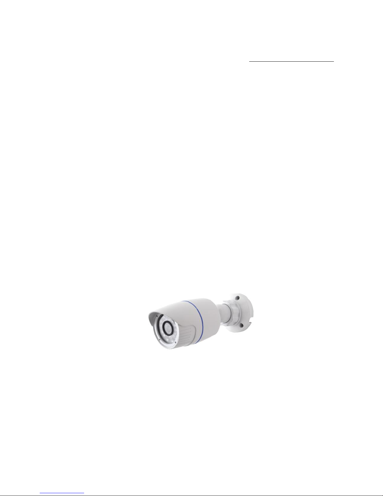
1.3 Mega Pixel
Water-Proof Network Camera
User Manual
Please read this instruction carefully for correct use of the product
Page 2

Before use this product
Before operation, we strongly advise users to read this manual and keep it
properly for using later.
This is product instructions not quality warranty. We may reserve the rights
of amending the typographical errors, inconsistencies with the latest version,
software upgrades and product improvements, interpretation and
modification. These changes will be published in the latest version without
special notification.
When this product is in use, the relevant contents of Microsoft, Apple and
Google will be involved in. The pictures and screenshots in this manual are
only used to explain the usage of our product. The ownerships of trademarks,
logos and other intellectual properties related to Microsoft, Apple and Google
belong to the above-mentioned companies.
Page 3

IP CAMERA USER MUANUAL
Table of Contents
1 Introduction…………………………………………………………………………….1
1.1 Summarization .........................................................................................................................................1
1.2 Check Package Content............................................................................................................................1
1.3 Connection ...............................................................................................................................................1
2 Installation………………………………………………………………………………2
2.1 Install IP-CAM to Ethernet Network ...............................................................................................2
2.2 Install CMS ......................................................................................................................................2
3 IE Remote Access……………………………………………………………………….5
3.1 LAN .................................................................................................................................................5
3.1.1 Access through IP-Tool ............................................................................................................5
3.1.2 Directly Access through IE .......................................................................................... 7
3.2 WAN ................................................................................................................................................8
4 Remote Preview………………………………………………………………………..10
4.1 The Remote Preview Interface ................................................................................................ .......10
4.2 Record Playback ............................................................................................................................10
4.3 Right-click Function ...................................................................................................................... 11
4.4 Snap Pictures ................................................................................................................................. 11
5 Remote Live Surveillance……………………………………………………………..13
5.1 System Configuration ....................................................................................................................13
5.1.1 Basic Information ..................................................................................................... 13
5.1.2 Date & Time Configuration ....................................................................................... 14
5.2 Video Configuration ......................................................................................................................14
5.2.1 Camera Configuration ............................................................................................... 14
5.2.2 Video Stream ........................................................................................................... 15
5.2.3 Time Stamp ............................................................................................................. 15
5.3 Alarm Configuration ......................................................................................................................16
5.3.1 Motion Detection Area .............................................................................................. 16
5.3.2 Motion Detection Trigger .......................................................................................... 16
5.3.3 Motion Detection Schedule ........................................................................................ 17
5.4 Network Configuration ..................................................................................................................18
5.4.1 Port ........................................................................................................................ 18
5.4.2 Wired ..................................................................................................................... 18
5.4.3 NET Traversal Configuration ..................................................................................... 19
5.4.4 Server Configuration ................................................................................................. 20
5.4.5 IP Notify ................................................................................................................. 20
5.4.6 DDNS Configuration ................................................................................................ 21
5.4.7 RTSP ...................................................................................................................... 23
5.4.8 UPNP ..................................................................................................................... 24
5.4.9 Mail Setting ............................................................................................................. 24
5.4.10 FTP ........................................................................................................................ 25
5.5 Advanced Configuration ................................................................................................................26
5.5.1 User Configuration ................................................................................................... 26
Page 4

IP CAMERA USER MUANUAL
5.5.2 Onvif Configuration.................................................................................................. 27
5.5.3 Security Configuration .............................................................................................. 28
5.5.4 Configure Backup & Restore ..................................................................................... 28
5.5.5 Reboot Device ......................................................................................................... 29
5.5.6 Upgrade .................................................................................................................. 29
6 Mobile Surveillance…………………………………………………………………...30
6.1 Network Configuration ..................................................................................................................30
6.2 By Phones with Windows Mobile OS ............................................................................................30
6.3 By Phones with iPhone OS ................................ ................................ ............................................34
6.4 By Phones with Android OS ..........................................................................................................44
6.5 By Phones With Blackberry OS .................................................................................................48
7 Use method for IP-TOOL…………………………………………………………….50
8 Q & A…………………………………………………………………………………..53
9 Specification…………………………………………………………………………...55
Page 5
Page 1
IP CAMERA USER MUANUAL
1 Introduction
1.1 Summarization
This IP-CAMERA (short for IP-CAM) is designed for high performance CCTV
solutions. It adopts state of the art video processing chips. It utilizes most advanced
technologies, such as video encoding and decoding technology, complies with the
TCP/IP protocol, SoC, etc to ensure this system more stable and reliable. This unit
consists of two parts: the IP-CAM device and central management software (short for
CMS). The CMS centralizes all devices together via internet or LAN and establishes a
sound surveillance system to realize unified management and remote operation to all
devices in one network.
This product is widely used in banks, telecommunication systems, electricity power
departments, law systems, factories, storehouses, uptowns, etc. In addition, it is also an
ideal choice for surveillance sites with middle or high risks.
1.2 Check Package Content
The pictures below are only for reference. Please make the object as the standard.
IP-CAMERA
Quick Start Guide
CD
Accessories
Description
IP-CAMERA
The device without Lens
Quick Start Guide
The Brief instructions of the product
CD
CD-ROM with software and manual
1.3 Connection
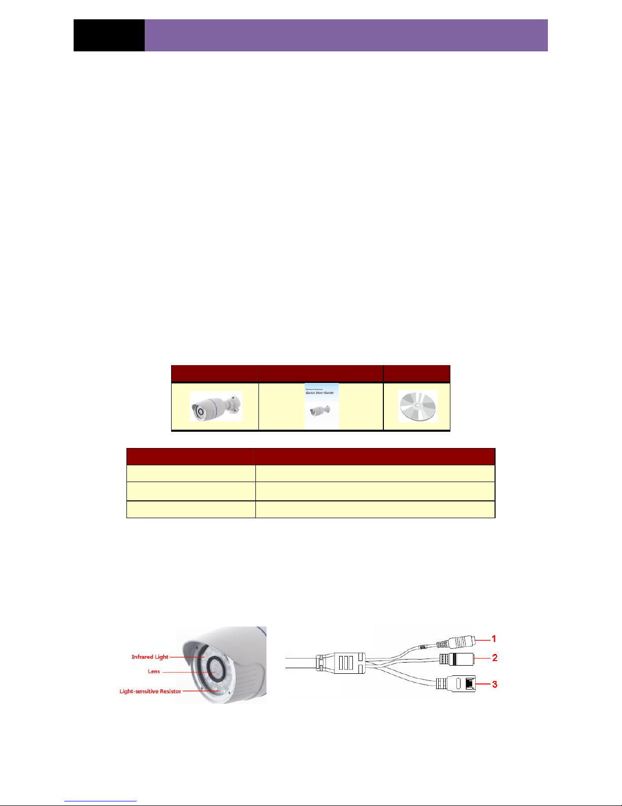
The IP-CAM supports 10m~15m IR distance. The below figures will introduce the
appearance and function of interfaces.
1. MIC: connect to MIC
2. DC12V: connect to power supply
3. LAN: network port; support PoE power supply
Page 6
Page 2
IP CAMERA USER MUANUAL
2 Installation
2.1 Install IP-CAM to Ethernet Network
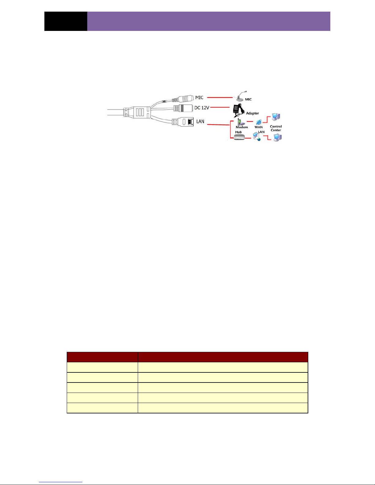
The connection of digital video server is show below.
Figure 2-1 Connection
User can connect the PC and IP-CAMERA in accordance with above picture. Before
connecting, please connect external devices, and then connect the power.
The connection steps are as shown below:
Step 1: Connect IP-CAM firstly.
Step 2: Internet line connect to Internet transfer equipment or devices
Step 3: Connect power cable to a power outlet.
2.2 Install CMS
After the CDD IP-CAM connected to the Ethernet, user can remote monitoring and
managing the device by using client software or IE browser. This chapter is the client
software, which is the quick install guide of the CMS, the operation and monitor setting
details please refers to CMS user manual in CD.
Note: Before to install control center software in user’s computer, please make sure
all anti-virus software in the computer closed so that CMS can install correctly.
System requirement
Supported Operating System:
Operating system
Comments
Windows XP
Windows XP SP2 or most updated patch; Direct 9.0c or above
Windows Vista
Windows Vista; Direct 10. c
Window 7
Window 7 Ultimate
Windows 2003
Windows 2003 serve or Directx 9.0c or above
Windows 2000
Windows 2000 SP4 or Directx 9.0c or above
Computer hardware requirement
Please make sure the software running well and the computer is compatible :
Recommended PC Specification – 4 channels
Page 7
Page 3
IP CAMERA USER MUANUAL
Item
Specification
CPU
Intel Pentium 3.0 GHz or AMD 3000+
Memory
1GB
HDD
160GB
Recommended PC Specification -9 channels:
Item
Specification
CPU
Intel Core 2 Duo 1.8 GHz or AMD Dual core 3800+
Memory
1GB
HDD
250GB
Recommended PC Specification -16 channels:
Item
Specification
CPU
Intel Core 2 Duo 2.2 GHz or AMD Dual core 3800+
Memory
2GB
HDD
250GB
Notice:
The mentioned specifications are provided considering CIF real-time resolution.
The AMD chip hyper-3800+ and X64 series are not tested.
For real-time view at CIF, max 25 channels can be played concurrently.
For real-time view at D1, max 6 channels can be played concurrently.
Installation Process
1. We would recommend that the anti-virus software is disabled before initiating the
installation. In addition, the setting of your IE browser must be enabled to download
ActiveX components.
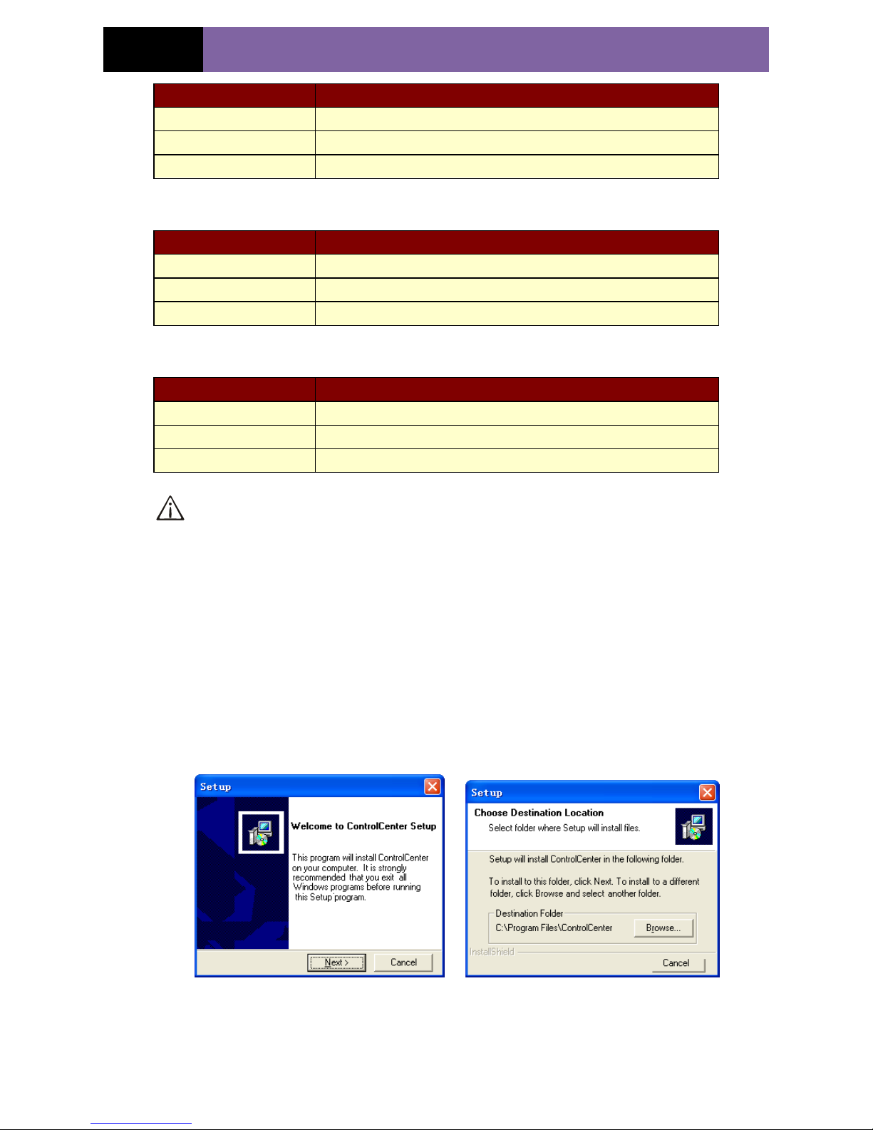
2. Run the „Setup.exe‟ from software CD. Then the next menu will pop up.
Figure 2-2 Welcome menu Figure 2-3 Choose the installation destination
3. The default installation destination folder is “C:\Program Files”, user could click
“Browser” button to change it. After selecting the destination, click “Next” to enter the
Page 8
Page 4
IP CAMERA USER MUANUAL
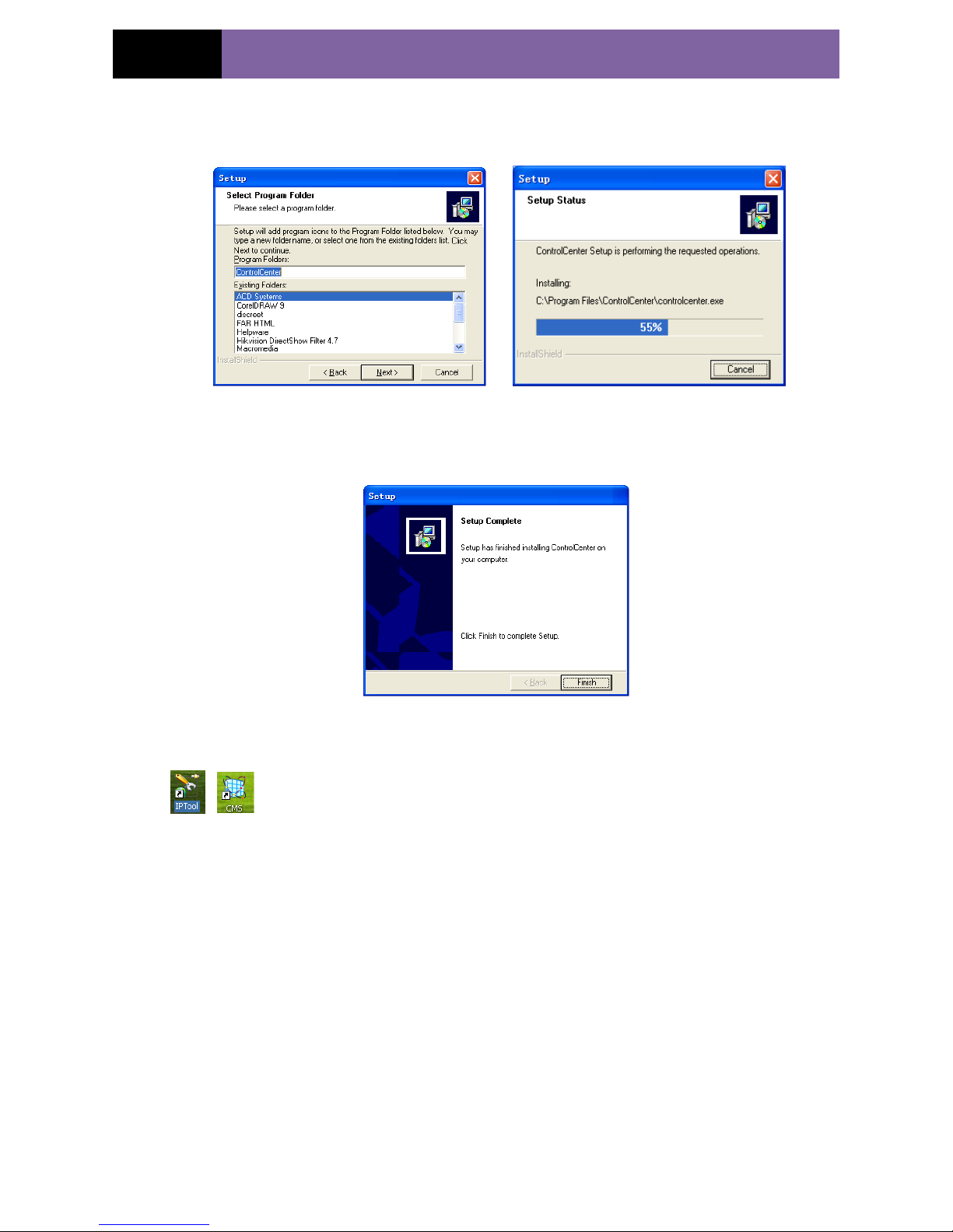
next step as Fig 2-4:
4. Click “Next” to start installing as Fig 2-5:
Figure 2-4 Select a folder to install Figure 2-5 The rate of installation progress
5. The installation is completed as Fig 2-6:
Figure 2-6 Completed menu
6. Click “Finish” to complete setup, then user can see the icon of “Control Center”
on the desktop.
7. Double click CMS icon to start the software, the initial user name is “system”, and
password is “123456”, user can change it in the corresponding chapter, the detail
introduction refers to “user manager” in user manual.
If you just want to user IP-tool, there is no necessary to install CMS software. You can
open the CD and find the IP-tool icon and double click it to run.
Page 9
Page 5
IP CAMERA USER MUANUAL
3 IE Remote Access
User can connect IP-Cam through LAN or WAN. Here only take IE browser (6.0)
for example. The details are as follows:
3.1 LAN
In LAN, there are two ways to access IP-Cam: 1. access through IP-Tool; 2. directly
access through IE browser.
3.1.1 Access through IP-Tool
Step 1: Make sure the PC and IP-Cam are connected to the LAN and the IP-Tool is
installed in the PC from the CD.
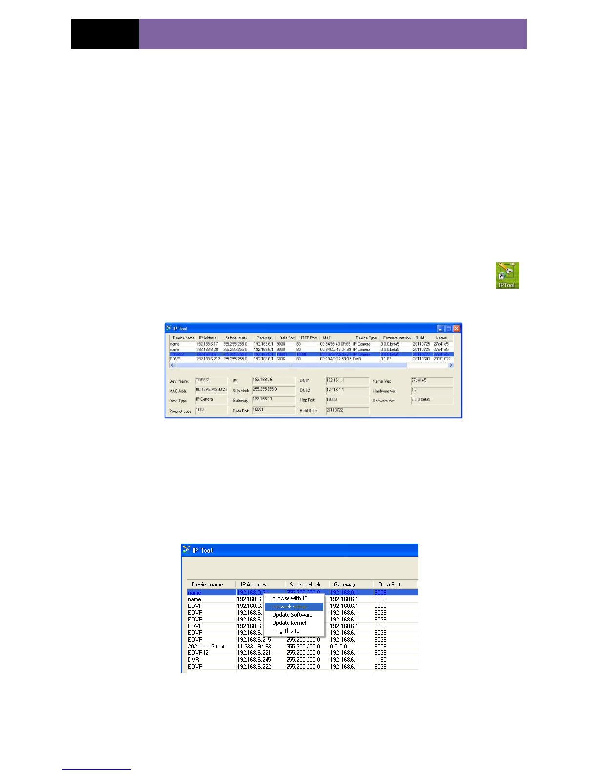
Step 2: Use IP-Tool to modify the network of IP-Cam. Then, double click the
icon on the desktop to run this software as shown below:
After starting IP-Tool and clicking the IP-Cam in the list, user can check the information
of IP-Cam. If user cannot confirm which one is himself, please shut off the electricity of
the IP-Cam and then power on it. When shutting off the power, the device information
will disappear. When powering on, the device information will emerge. Well, this device
is the used device. Right click the device information and select “network setup”. Then
the network setup window will pop up as shown below:
Page 10
Page 6
IP CAMERA USER MUANUAL
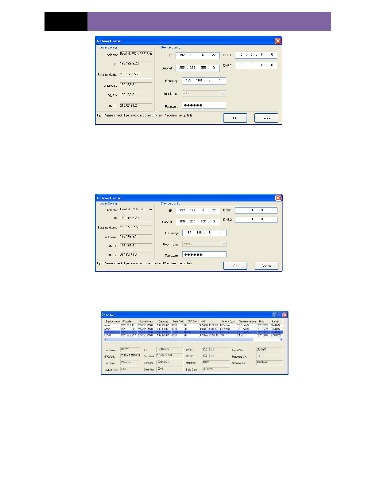
For example, the network segment of this computer is 192.168.x under the local config
table. So, please modify the IP address, Subnet Mask, Gateway of IP-Cam which must
be in the same network segment with the computer. Take 192.168.6.22 for example.
After modifying, please input the user name and password and then click “OK” button
to save the setting.
Note: The default user name is: admin. The default password is: 123456.
The new IP address of this device will display as follows after modification.
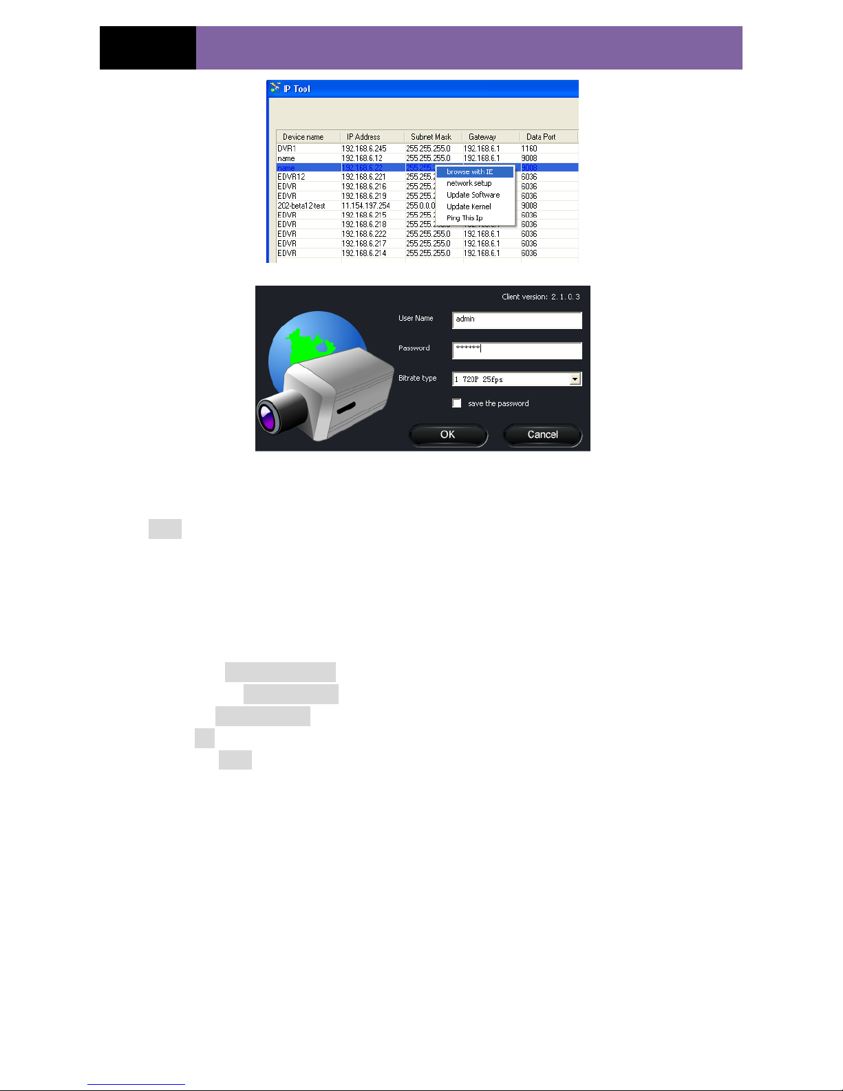
Step 3: Use the IP-Tool to login the IP-Cam.
Right-click the IP address and select “browse with IE”. Then the system will pop up the
IE browser to connect IP-Cam as shown below. IE browser will auto download the
Active X control. If the IE browser cannot download the Active X control, please refer
to Q4 of Chapter 8. Finishing the installation of the Active X control, a login window
will pop up.
Page 11
Page 7
IP CAMERA USER MUANUAL
Input User name and password and then click “OK” button to login.
Note: User also can use the modified IP address of the IP-Cam. Input the IP address in
the IE browser bar and then click “Enter” to access IP-Cam. The default user name is
admin. The default password is 123456.
3.1.2 Directly Access through IE
The network service is default as shown below:
IP address: 192.168.226.201
Subnet Mask: 255.255.255.0
Gateway: 192.168.226.1
HTTP: 80
Data port: 9008
When use the IP-CAM for the first time, please connect the device with the above
default settings.
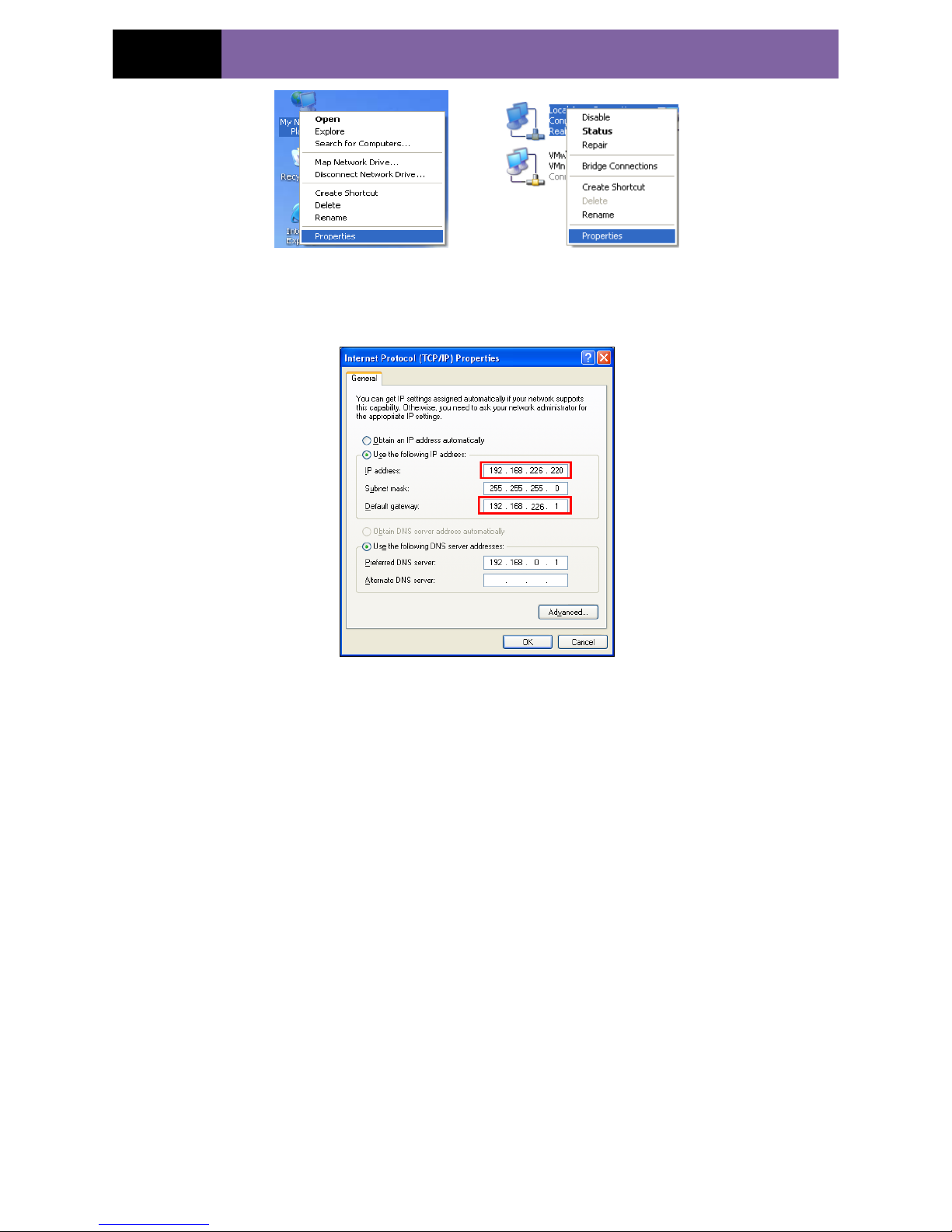
Step 1: Manual setup the IP address of the PC, the network segment should be as same
as the default settings of IP-CAM. Right click “My Network Places” icon on the
desktopselect “properties” as shown in the left figure. Right click “Local Area
Connection” at the pops up window, and then select “property” as shown in the right
figure.
Page 12
Page 8
IP CAMERA USER MUANUAL
Select “Internet Protocol (TCP/IP)” in the “General” tabsclick “properties”manual
input network address information of the PC in the pop up window.
Step 2: Open the IE Browser, input the default address of IP-CAM and confirm, the IE
browser will download Active X control automatically. If IE browser can‟t download
Active X control, please refer to Q4 of chapter 8.
Step 3: After downloading Active X control, the login dialog box will pop up as below:
Step 4: input user name and password in the login dialog box and click “OK” button to
enter into the live interface refer to the following figure. User can manage and setup the
IP-CAM, such as change IP address etc.
3.2 WAN
a. Access through router or virtual server
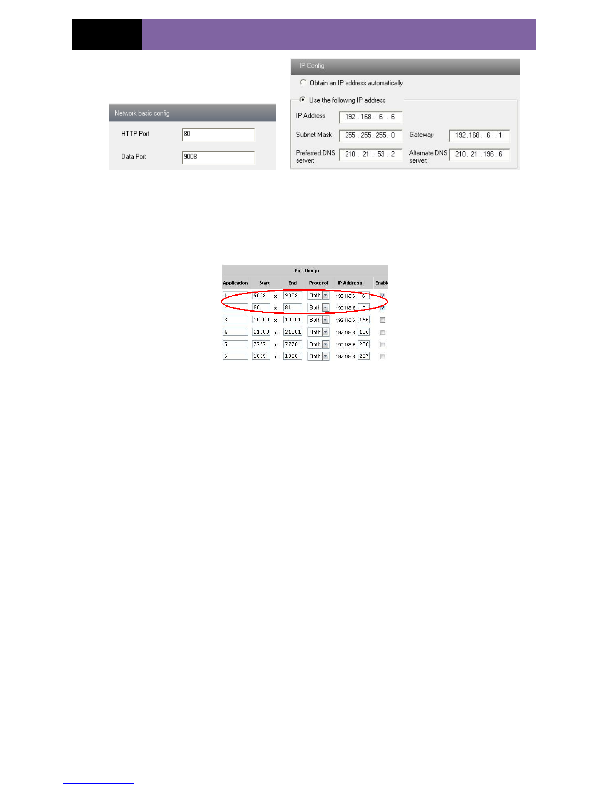
Step1: Connecting according to above steps in LAN; enter into System
ConfigurationNetwork configurationBasic configuration to setup the port number
as shown in Fig 3-1:
Step 2: Enter into System ConfigurationNetwork configurationIP configuration to
change IP address as shown in Fig 3-2:
Notice: The steps above should be saved after the change of the port and IP address.
Log back in the device with the saved setting.
Page 13
Page 9
IP CAMERA USER MUANUAL
Fig 3-1 Port setup Fig 3-2 IP setup
Step 3: Enter into the router‟s management interface through IE browser; remap the IP
address and port of IP-CAM in the “virtual server”. The name depends on the router.
Please refer to Fig 3-3:
Fig 3-3 IP remap
Step 4: Open the IE browser and input its WAN IP and http port to access. The
following steps are as same as “Step 2, 3 and 4” of Chapter 3.1.2 in LAN.
Page 14
Page 10
IP CAMERA USER MUANUAL
4 Remote Preview
4.1 The Remote Preview Interface
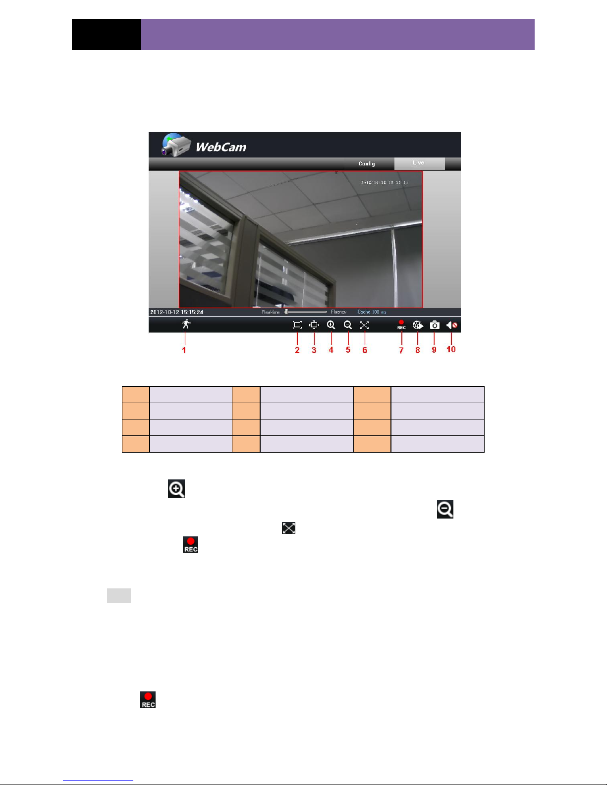
Fig 4-1 Remote Preview
When motion detection alarm is triggered, the people icon turn red.
Click icon, user can zoom in the preview image to suitable size, drag the
cursor on the enlarged image to view suitable preview area; click icon, user can
zoom out the enlarged image; click icon, user can full-screen the live image.
Clicking icon will appear a save path window and the record file can save on
user‟s PC.
Note: On Window 7 and Window Vista, user can not record or snap pictures until UAC
function is disabled. Please refer to following steps: Start—Control panel—User
accounts—Change user account control settings in which user needs to drag the scale to
Always notify end and then click “OK” button to save.
4.2 Record Playback
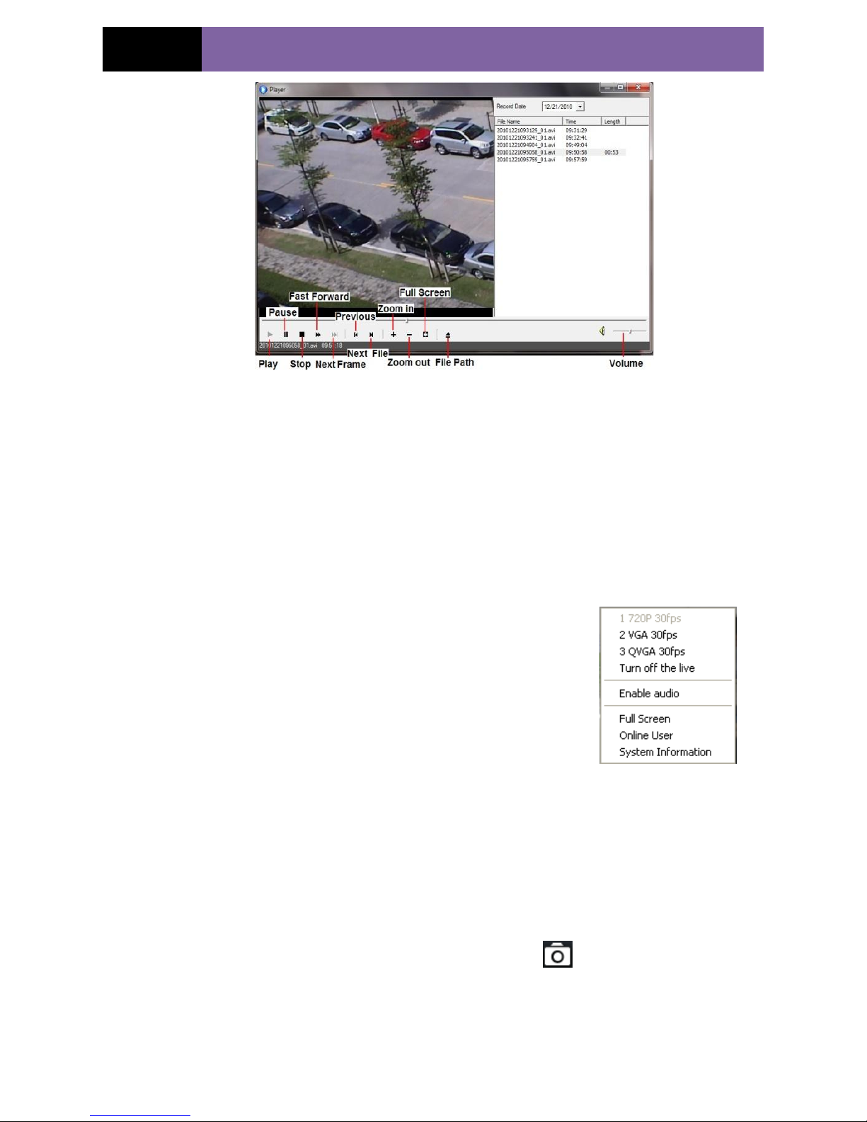
Click icon and refer to Fig 4-2:
1
People icon
2
Fix size
3
Zoom in
4
Zoom in
5
Zoom out
6
Full screen
7
Start record
8
Playback
9
Snap
10
Enable audio
Page 15
Page 11
IP CAMERA USER MUANUAL
Fig 4-2 record playback interface
After selecting the record date, the record files will be displayed in the record file list
box. User can double click a
certain record file to playback or check a certain file. Then click Play button to do
playback. User can do relating operation according to some buttons in the playback
interface.
4.3 Right-click Function
Clicking right mouse will appear a pull-down list as below:
Stream: 720P, VGA, QVGA, QQVGA.
Turn off the live: Click this item will close present live
preview.
Enable audio: Enable remote audio transmission. Users can
hear the audio from the IP-CAM.
Full screen: The live preview picture will full-screen display.
Double click or click right mouse to return to the previous
interface. Fig 4-3 Right key sub-menu
Online user: Display user‟s list connect to the device.
System information: Display the device information: device name, firmware version,
software build date, kernel version and hardware version.
4.4 Snap Pictures
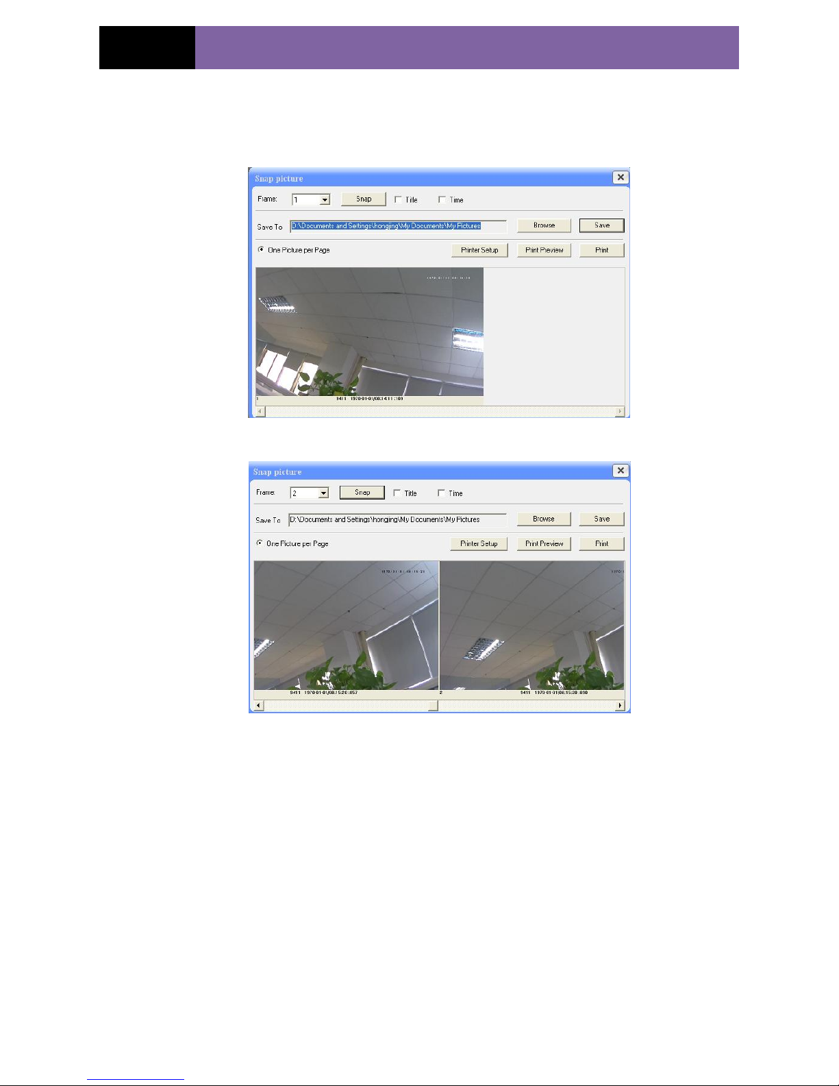
1. Select the picture number, and then click “Snap” icon as shown in the Fig
4-4:
2. User can snap multiple pictures. Select the picture number from Frame pull down
list box, such as 3, and check “Title” and “Time” to show capture title and time on the
snap pictures simultaneously. Refer to Fig 4-5:
Page 16
Page 12
IP CAMERA USER MUANUAL
3. Click “Browse” to set saving path; Click “Save” to save pictures to HDD on the
computer; Click “Printer setup” to set the printer and print the snap pictures; drag the
scroll bar to view all snapped pictures.
Fig 4-4 Single Snap
Fig 4-5 Multi-picture Snap
Page 17
Page 13
IP CAMERA USER MUANUAL
5 Remote Live Surveillance
User can remote setup the parameters of the device. Functions of remote configurations
include: System Configuration, Video Configuration, Alarm Configuration, Network
Configuration and Advanced Configuration. User should firstly select the menu on the
left, and then setup the relative parameters. When a user setup parameters of a certain
device, other users can not setup this device.
5.1 System Configuration
The “System configuration” includes two submenus: Basic Information and Date &
Time.
5.1.1 Basic Information
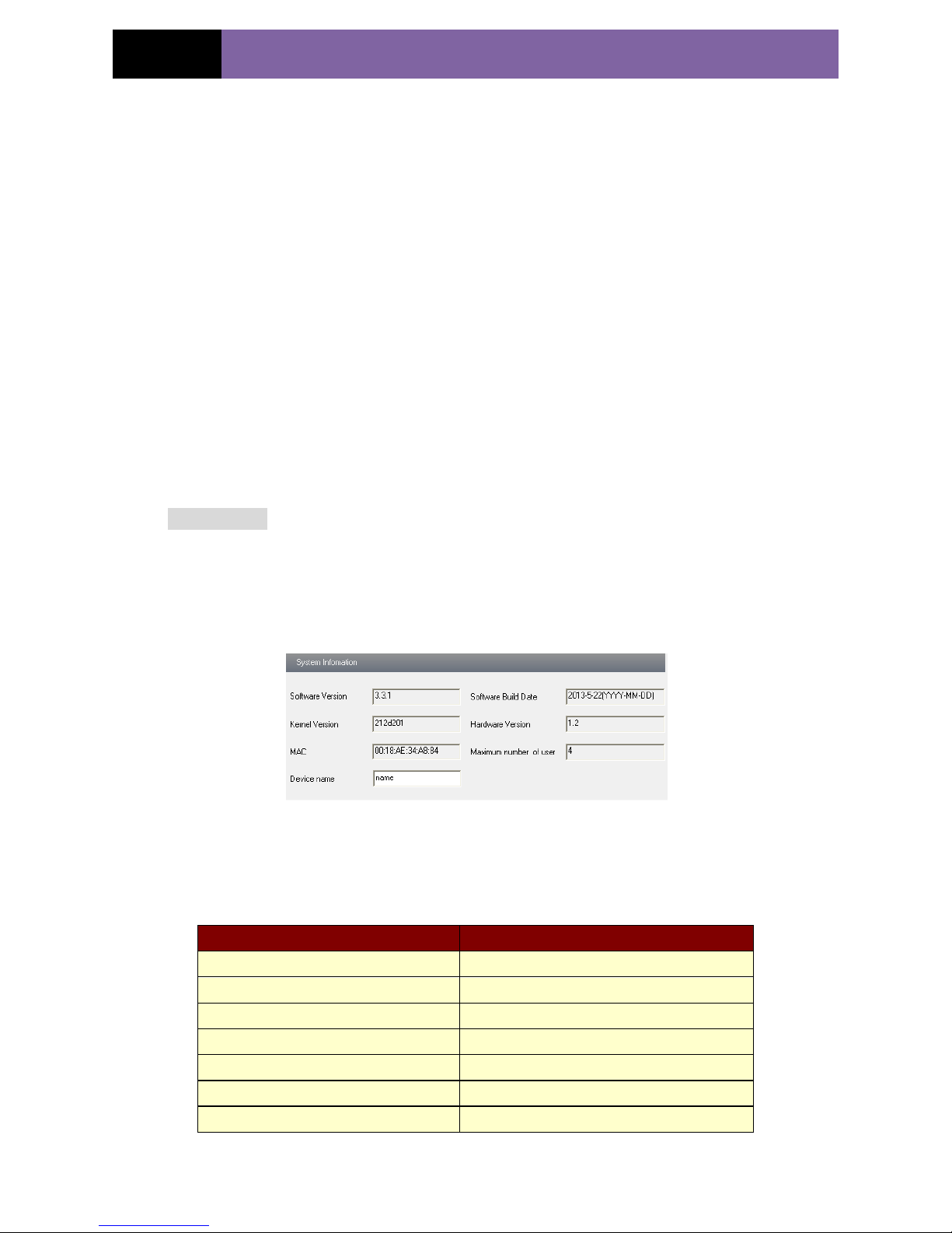
In the “Basic Information interface, user can setup the device name and also can check
the relative information of the server
Setting steps:
1. Clicking the "Config" icon will appear the menu list.
2. Clicking the “Basic Information "will pop up a window as shown in Fig 5-1:
3. Input the name of the device in the "Device name" text box.
4. Press the "Save" button to save the settings.
Fig 5-1 Basic Information Config
Please refer to the following table for parameters and instructions of server basic
configuration.
Parameter
Meaning
Software version
The software of the device
Software build date
The software build date of the device
Kernel version
The kernel version of the device
Hardware version
The hardware version of the device
Mac Address
MAC address of device
Maximum number of user
Support max 4 users to access
Device name
Name of the device.
Page 18
Page 14
IP CAMERA USER MUANUAL
5.1.2 Date & Time Configuration
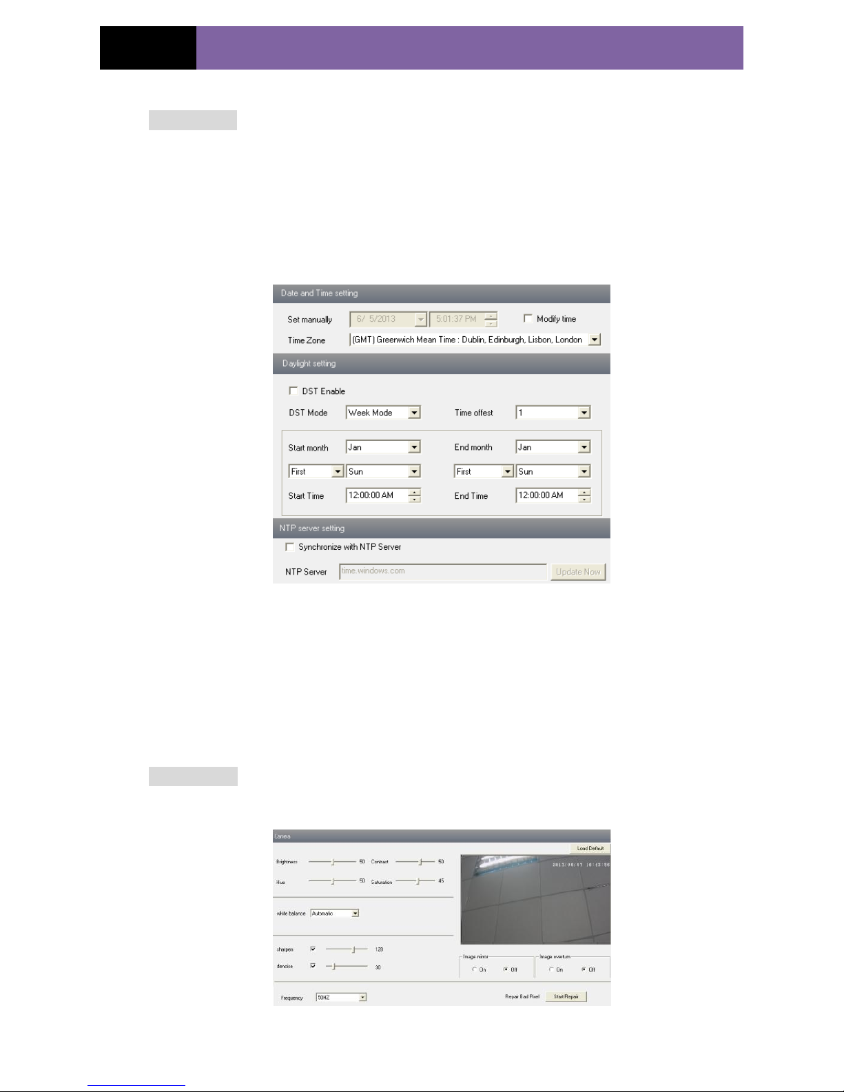
Setting steps:
1. Enter into "System Configuration" “Date & Time”. Refer to Fig 5-2:
2. Select “Modify Time ", user can self-define time. Choose the right "Time Zone"
according to user‟s location.
3. User can also enable DST and set DST mode and time.
4. User can setup time by select the “Synchronize with NTP Server”.
5. Press the "Save" button to save the settings.
Fig 5-2 Date &Time Config
5.2 Video Configuration
Camera Configuration includes three submenus: Camera Configuration, Video Stream
and Time Stamp.
5.2.1 Camera Configuration
Setting steps:
1. Enter into "Video Configuration " "Camera" interface as shown in Fig 5-3:
Fig 5-3 Basic Configuration
Page 19
Page 15
IP CAMERA USER MUANUAL
2. User can adjust Brightness, Contrast, Hue and saturation of the picture.
3. Select white balance mode.
4. Sharpen, denoise and frequency are adjustable.
5. User also can enable the image mirror and image overturn function.
6. Press the "Save" button to save the settings.
5.2.2 Video Stream
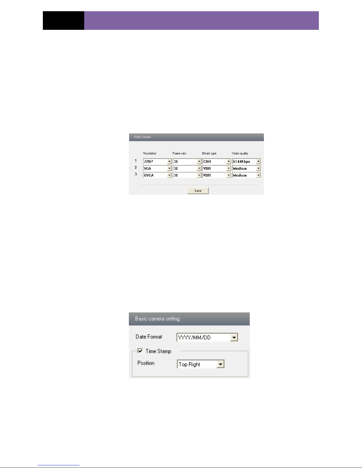
1. Enter into "Video configuration" "Video Stream" to see a interface shown as Fig
5-4:
Fig 5-4 Video Stream
2. Select the resolution of the single frame image at the "Resolution" pull down list.
3. Select the quantity of video per second at the "Frame rate" pull down list.
4. Select the data stream type at the "Bit rate type" pull down list.
5. Set the video quality at the "Video quality" pull down list.
6. Press the "Save" button to save the settings.
5.2.3 Time Stamp
Enter into "Video configuration""Time Stamp" to display the interface as shown
in Fig 5-5:
Fig 5-5 Time Stamp
1. Select Date Format to show in the live image.
Time stamp: time displayed in the live preview pictures. Four items can choose from:
top left, top right, bottom left and bottom right.
2. Press the "Save" button to save the settings.
Page 20
Page 16
IP CAMERA USER MUANUAL
5.3 Alarm Configuration
Alarm configuration includes three submenus: Motion Detection Area, Motion
Detection Trigger and Motion Detection Schedule.
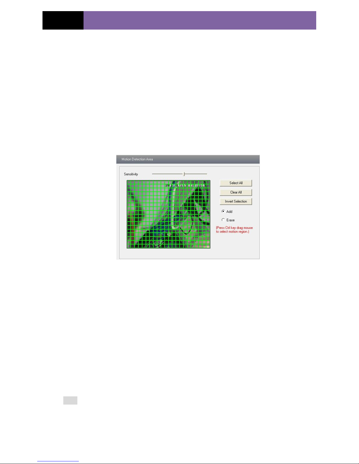
5.3.1 Motion Detection Area
1. Enter into “Alarm configuration""Motion Detection Area" to see a interface shown
as Fig 5-6:
2. Move the "Sensitivity" scroll bar to setup the motion trace sensitivity.
3. Check the "Add”, press the "Ctrl" button and move mouse to select the motion
detection area; Select “Erase” and move the mouse to clear all motion detection area.
4. Press the "Save" button to save the settings.
Fig 5-6 Motion Detection Area
5.3.2 Motion Detection Trigger
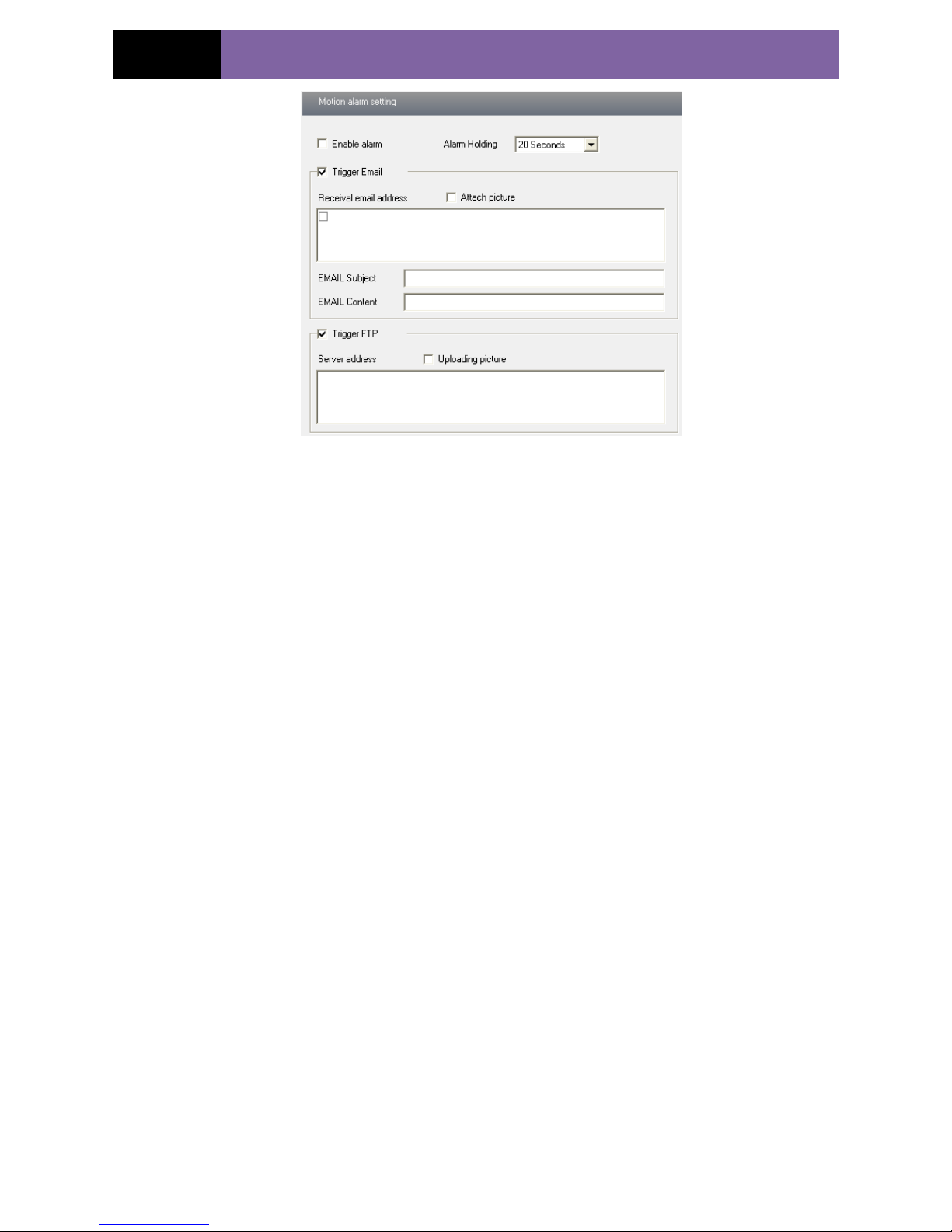
1. Enter into “Alarm Configuration" "Motion Detection Trigger" to display a
interface as shown in Fig 5-7:
2. Check "Enable alarm" check box. Then all functions under this interface will be
activated.
4. Trigger Email: Check “Attach picture” and select email addresses in the “Receival
email address” text box(Email address shall be set first in the Mail config
interface).Then the triggered snap pictures will be sent into those address. User also can
define the subject and content of the email.
5. Trigger FTP: Check “Uploading picture”. Then the triggered snap pictures will be
sent into FTP server address.
Note: Please refer to FTP configuration chapter for more details.
6. Press the "Save" button to save the settings.
Page 21
Page 17
IP CAMERA USER MUANUAL
Fig 5-7 Motion Alarm Trigger
5.3.3 Motion Detection Schedule
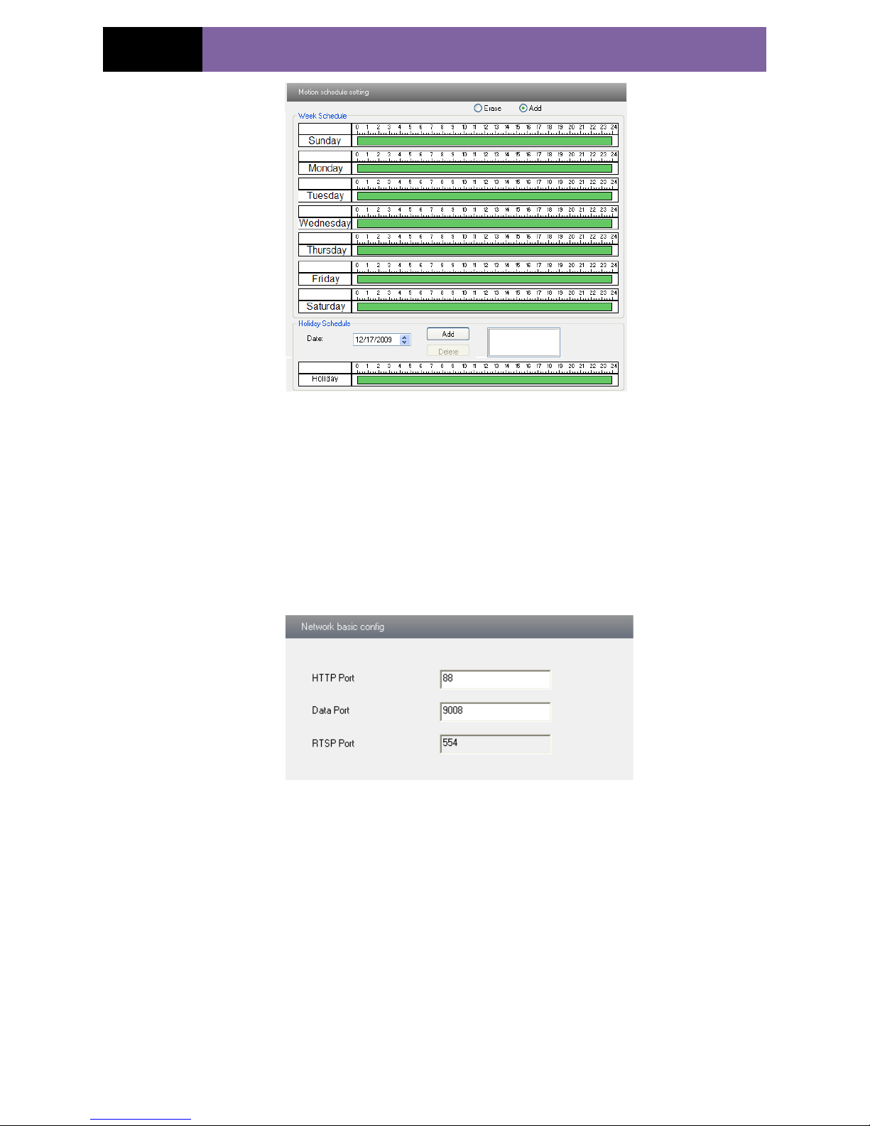
Enter into “Alarm configuration" "Motion Detection schedule" interface as shown in
Fig 5-8:
Week schedule
User could set the alarm time from Monday to Sunday for alarm everyday in one week.
Note: The lengthwise means one day of a week; the rank means 24 hours of a day.
Mouse clicks on the pane to set the alarm hours. Green means selected area. Blank
means unselected area.
2."Add": add the schedule for a special day.
3."Erase": delete holiday schedule
Day schedule
User could set alarm time for alarm in some time of special day, such as holiday.
1. Select a date at the "Date" pull down list, press "Add" button to add that date to the
list box on the right side and then move the scroll bar to set the schedule of that day.
2. Select a date in the list box on the right side, and press "Erase" to remove the
schedule on that day.
Press the "Save" button to save the settings.
Note: Holiday schedule is prior to Week schedule.
Page 22
Page 18
IP CAMERA USER MUANUAL
Fig 5-8 Motion Detection Schedule
5.4 Network Configuration
Network configuration includes ten submenus: Port, Wired, NET traversal Config,
Server Configuration, IP Notify, DDNS Config, RTSP, UPNP, Mail Setting and FTP.
5.4.1 Port
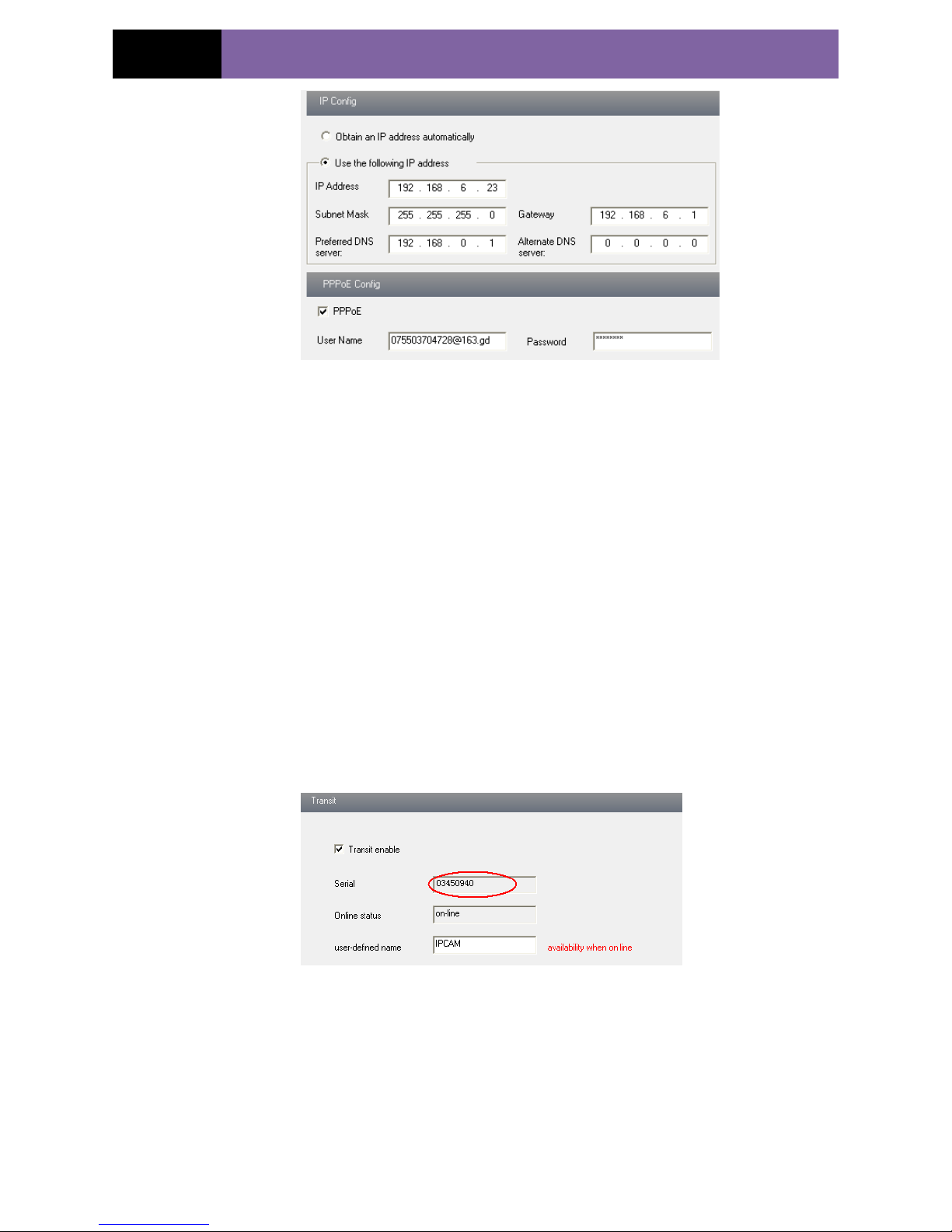
1. Enter into "Network config""Port" to see the interface as shown in Fig 5-9:
Fig 5-9 Port Config
2. Input port number for IE access in the "HTTP Port" textbox.
3. Input the port number for audio & video transmission in the "Data Port" textbox.
5.4.2 Wired
1. Enter into "Network Configuration""Wired" to see a tab shown as Figure 5-10:
Page 23
Page 19
IP CAMERA USER MUANUAL
Fig 5-10 Wired Config
2. There are two Options for setup IP: obtain an IP address auto by DHCP protocol and
use the following IP address, user can choose one of options for requirements.
3. Use the following IP address: display the IP address, subnet mask, gateway and DNS
of the device.
4. PPPOE: User needs to manual input the user name and password for dial-up internet.
Firstly, user needs to login IE clients, then enter into user name and password of PPPoE,
save the setting and exit. Secondly, setup IP address change notice. Thirdly, connect
with Modem, then the device will dial-up internet automatically.
6. Press the "Save" button to save the settings.
5.4.3 NET Traversal Configuration
In this interface, user can access to network without dynamic domain name and port
forwarding by enabling NET transit.
1.Enter into “Network Configuration” “NET traversal Config”. Refer to Fig 5-11:
Fig 5-11 Transit
2. Check “transit enable”. Then save the setting.
3. Input www.upnpicp.com in IE address; download and install Active X. Then a window
shows up as Fig 5-12:
Page 24
Page 20
IP CAMERA USER MUANUAL
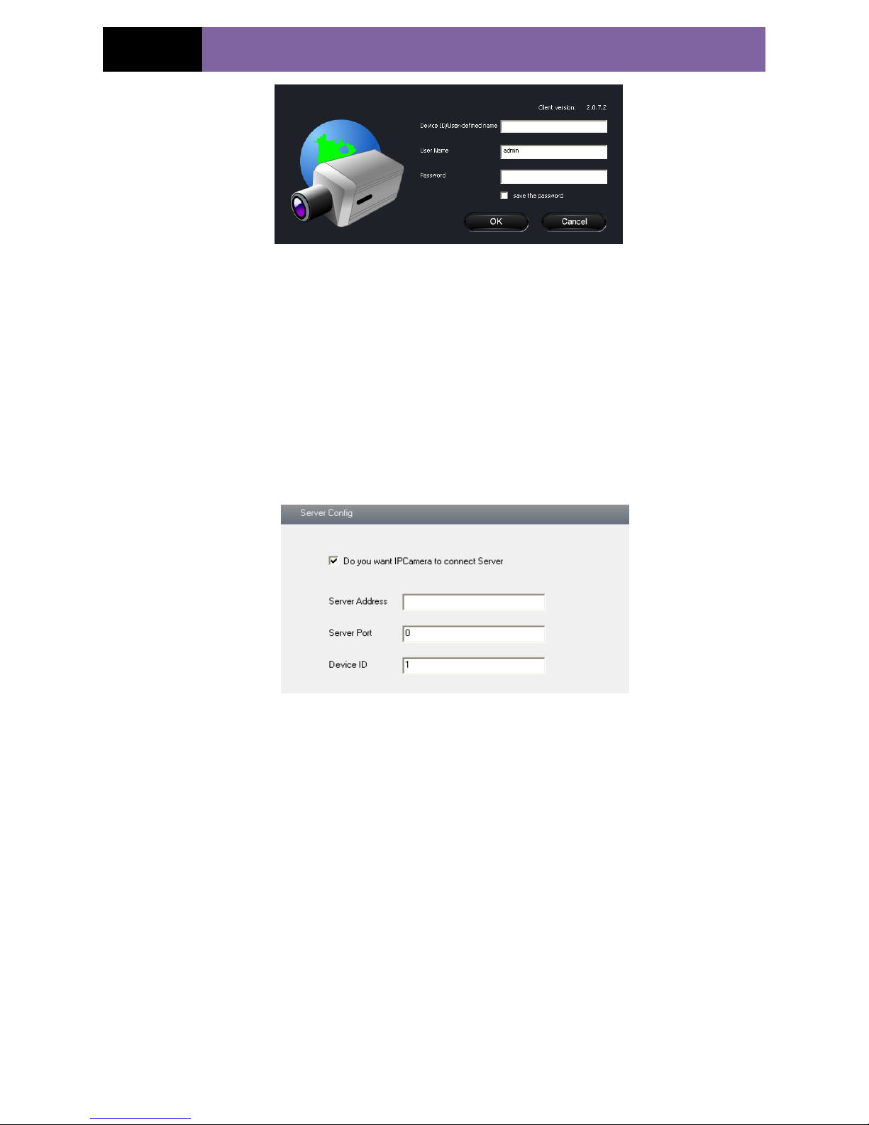
Fig 5-12 Login
4. Input the only device ID of the IP-CAM or user-defined name. And then input user
name and password.
Note: The default user name and password are “admin” and “123456”
respectively.
5.4.4 Server Configuration
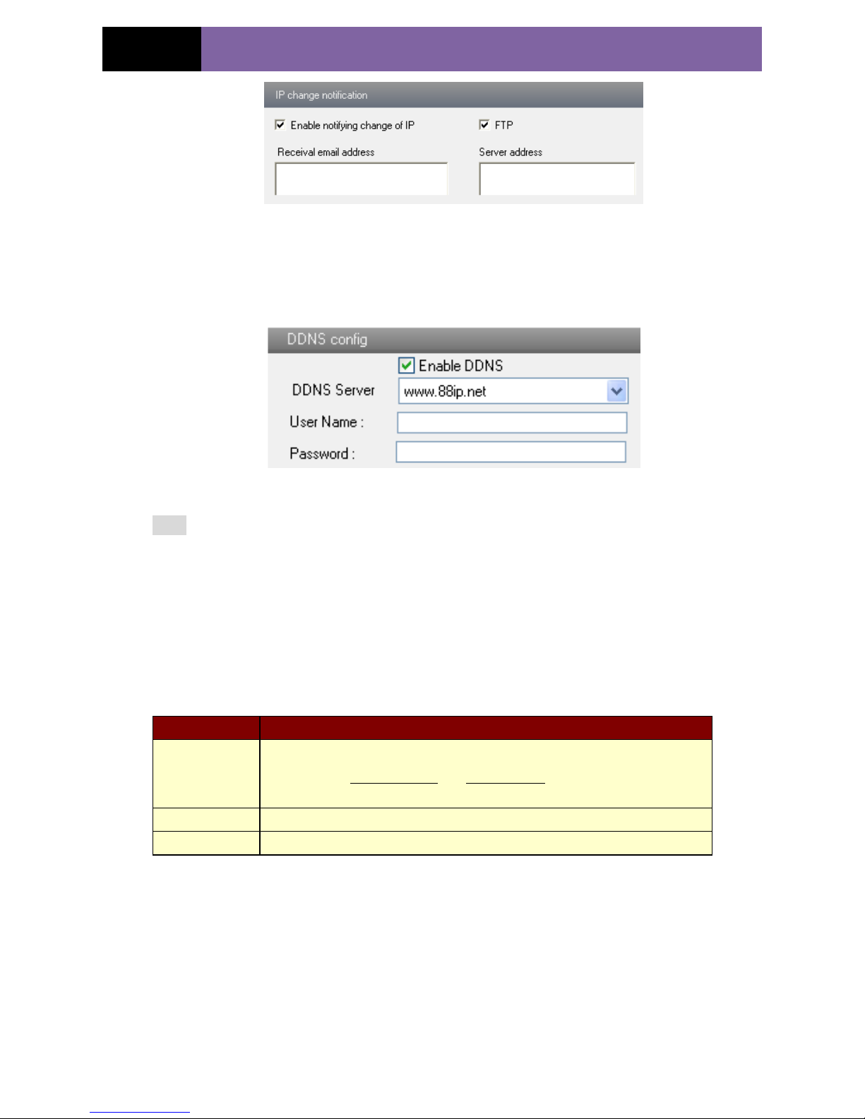
Enter into “Network Configuration” “Server Config”. Please refer to Fig 5-13:
Fig 5-13 Server Configuration
1. Check “Do you want IP Camera to connect Server.
2. Check the IP address and port of the transfer media server in the ECMS/NVMS. Then
enable the auto report in the ECMS/NVMS when adding a new device. Then input the
remaining information of the device in the ECMS/NVMS. After that, the system will
auto allot a device ID. Please check it in the ECMS/NVMS.
3. Input the above-mentioned server IP, server port and device ID in the responding
boxes. Click “save” button to save the settings.
5.4.5 IP Notify
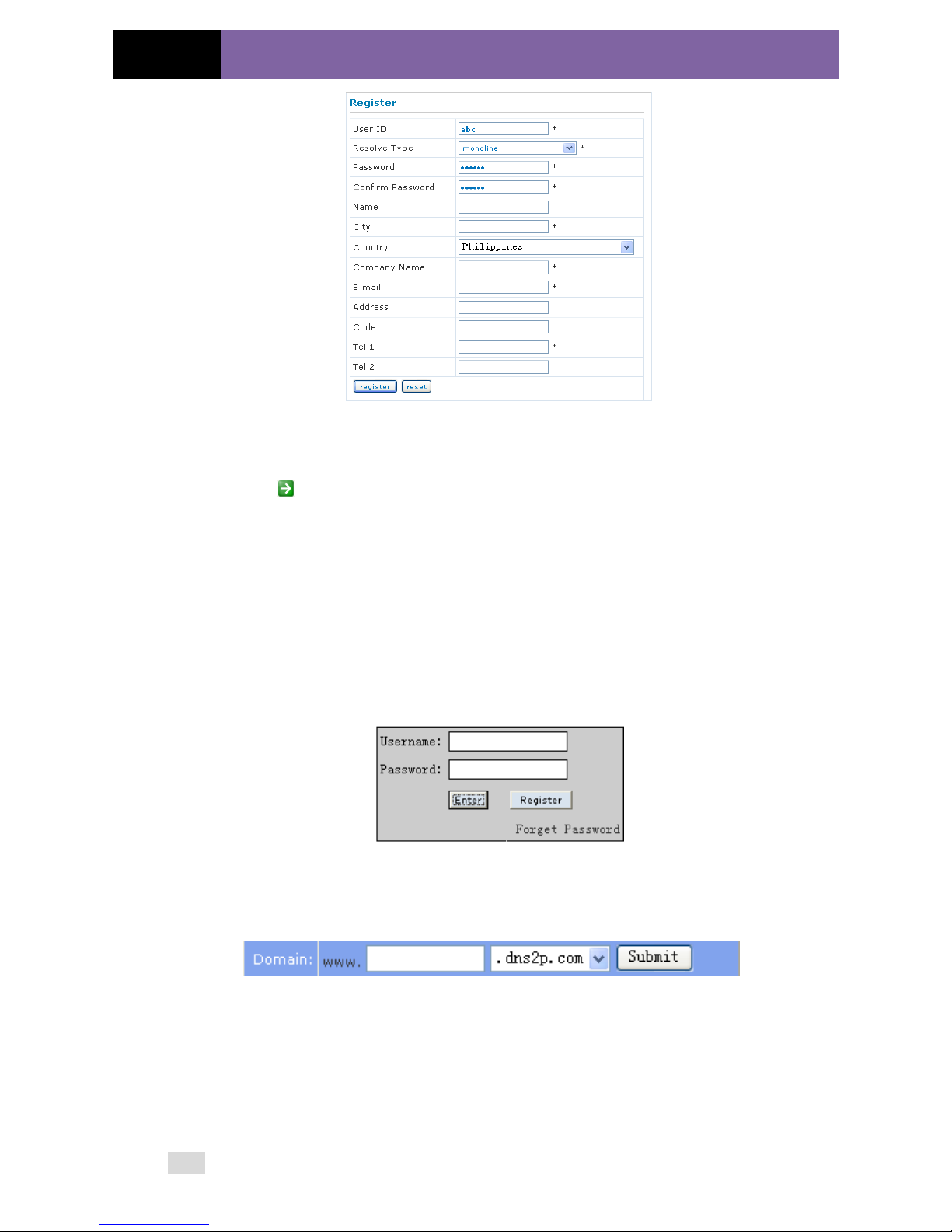
1. Enter into “Network Configuration””IP Notify” to see a tab as shown in Fig 5-14.
2. If the “Enable notifying change of IP” is selected, when the IP address of the device
is changed, a new IP address will be sent to the appointed mailbox automatically; If
“FTP” is selected, when the IP address of the device was changed, a new IP address will
be sent to FTP server.
Page 25
Page 21
IP CAMERA USER MUANUAL
Fig 5-14 IP Notify Config
5.4.6 DDNS Configuration
1. Enter into "Network Configuration""DDNS Configuration" tab as shown in Fig
5-15:
Fig 5-15 DDNS Config
Note: The steps to band a domain name for video surveillance server are as follows.
Firstly, register a user name and a password to log on the website of service supplier,
and then apply for a domain name online for the server. After that, users can visit the
server through inputting the domain name at IE terminal.
2. Press the "Save" button to save the settings.
Please refer to the following table for parameters and instructions of DDNS
configuration.
Parameter
Meaning
DDNS server
Address of the website which provided by domain name supplier. The
optional: www.dns2p.net , www.88ip.net ,www.meibu.com ,
www.dyndns.com,www.no-ip.com,www.3322.org and mintdns type.
User name
Log in the website of domain name supplier
Password
Log in the website of domain name supplier
1. Apply the Domain Name (Take dns2p for example)
(1) Register in the Web
Page 26
Page 22
IP CAMERA USER MUANUAL
Register dialog box
Step 1: Fill in the blank of IE address with „www.dns2p.com‟.
Step 2: Click to enter the website.
Step 3: Click "New User" in the right of homepage to register. For example: User ID is
„abc‟, and password is „123456‟. The register dialog display as below:
(2) Login
Step 1: Return to homepage after registering successfully.
Step 2: Click "Account Manager" on the right of homepage to login.
Step 3: Input the username and password with the information that you have registered.
Step 4: Click "Enter" key after filling in the textbox.
Log in
(3) Domain Setup
Step 1: Click "Domain Management" on the left to set the domain.
Domain setup
Step 2: Input the domain in the textbox. For example, you set „IP-CAMERA‟ as the
domain.
Step 3: Click "Submit" button, the system will pop up a dialog box to show that the
domain is added successfully.
Note: Time of probationary period is one month. If user wants to use it continuatively
Page 27
Page 23
IP CAMERA USER MUANUAL
after one month, please Step 4: click "Buy Now" in the right of homepage to pay for it.
2. Setup in the IP-CAMERA
⑴ DOMAIN
Domain is set in „1. Apply the Domain Name‟. According to the example above, the
domain is „WWW. IP-CAMERA.dns2p.com‟.
⑵ USER ID
Username of registered which is set in „(1) Register in the Web‟. According to the
example above, user ID is „abc‟.
⑶ PASSWORD
Password is set in „(1) Register in the Web‟. According to the example above, password
is „123456‟.
Note: If the connection fails, press the "INFO" button. Now the system will display:
„DDNS NONE‟. Then you need to check network and information above and try again.
3. Application
Connect IP-CAMERA to the Network Client.
Step 1: After popping up the login interface, fill in "Server" textbox with „*.dns2p.com‟
to visit the Network Client of the IP-CAMERA. The domain set in „(3) Domain Setup‟.
According to the example above, fill in "Server" textbox with
„IP-CAMERA.dns2p.com‟.
Step 2: Click "save" button to save the above setting.
5.4.7 RTSP
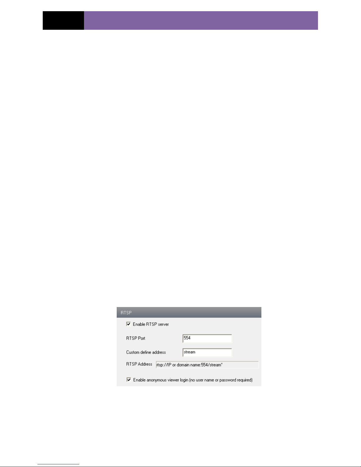
Enter into “Network Configuration” “RTSP” interface as shown in Fig 5-16:
Fig 5-16 RTSP
1. Select “Enable RTSP server.
2. RTSP Port: Access Port of the streaming media. The default number is 554.
3. Custom define address: User can self-define.
4.RTSP Address: An example of the RTSP address inputted in the media player.
Page 28

Page 24
IP CAMERA USER MUANUAL
5. You can also choose to enable anonymous viewer login
5.4.8 UPNP
Enter into “Network Configuration” “UPNP” interface as shown in Fig 5-17.
Select “Enable UPNP” and then input friendly name.
Fig 5-17 UPNP
Enable UPNP
Double-click the “My Network Places” icon on the desktop in PC and select “Show
icons for networked UPnP devices” in the “Network Tasks” list box. Then a
information window will pop up. Click “YES” button to see a “Windows Components
Wizard” dialog box pop up as shown below. Then press “Next” to continue. After
finished the installation of configuring components, the UPnP icons will display. Users
can double-click certain icon to connect the remote surveillance login interface through
IE.
If “Show icons for networked UPnP devices” can‟t display in the “Network Tasks” list
box, please follow the below operation:
Click “Tools”-- “Folder options”
Check the “Show common tasks in folders” in the “Tasks” check box, UPnP icon
will display.
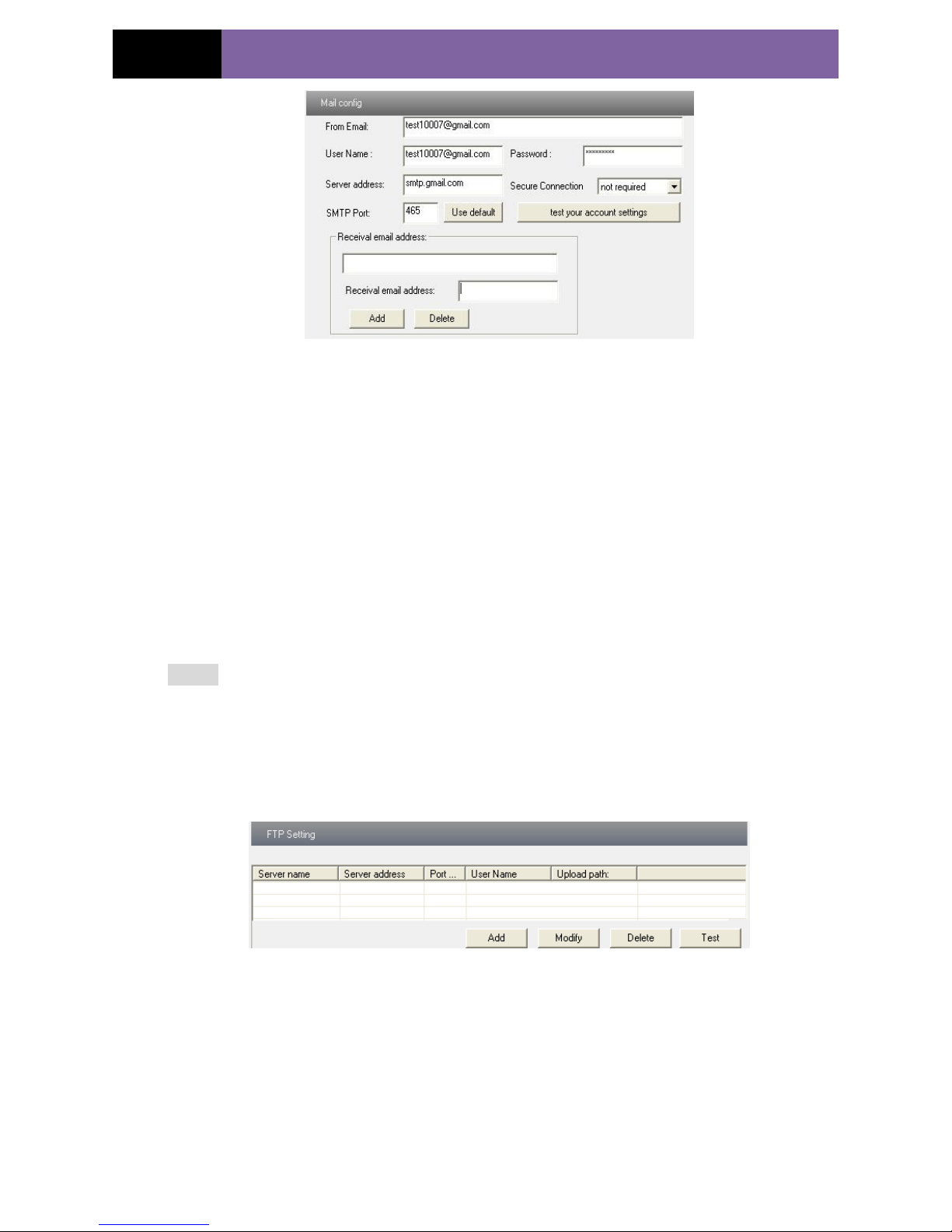
5.4.9 Mail Setting
Enter into “Network Configuration” “Mail Setting” interface. Please refer to Fig
5-18.
Page 29
Page 25
IP CAMERA USER MUANUAL
Fig 5-18 Mail Setting
1. From Email: sender‟s e-mail address
2. User name and password: sender‟s user name and password
3. Server address: SMTP name of sender
4.Select the secure connection type at the Secure Connection pull down list according to
user‟ actual needs
5. Receival email address list: add email address into the list
6. Receival email address: receiver‟s e-mail address
7. After all parameters setup, user can click “Test your account settings”. If email sent
successful, a “Test Successful” window will pop up, if not, users can try other email
addresses or check the setting.
Notice: If user change the static IP into PPPoE and select mailbox, there will be an
e-mail sent to users‟ mail box for notify a new IP address.
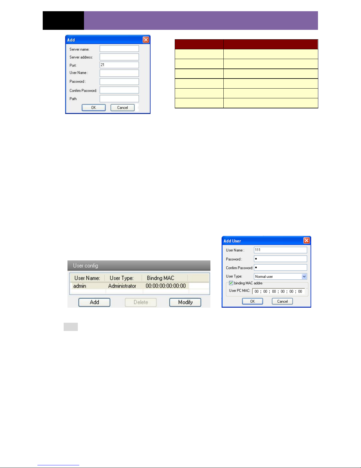
5.4.10 FTP
Enter into Network ConfigurationFTP interface; please refer to Fig 5-19:
Fig 5-19 FTP Setting
1. Add: Click Add button to input FTP server‟s server name, address, port number, user
name, password, and upload path, click OK to confirm the setting. Refer to Fig 5-20:
2. Modify:User can click this button to change some information of the FTP server
3. Delete:Select certain FTP account; Click this button to delete this account
4. Test :Select certain FTP account; Click this button to test its valid or not.
Please refer to the following table for parameters and instructions of FTP configuration.
Page 30
Page 26
IP CAMERA USER MUANUAL
Fig 5-20 Add
5.5 Advanced Configuration
Advanced configuration includes five submenus: User Configuration, Onvif
Configuration, Security Configuration, Configure Backup & Restore, Reboot and
Upgrade.
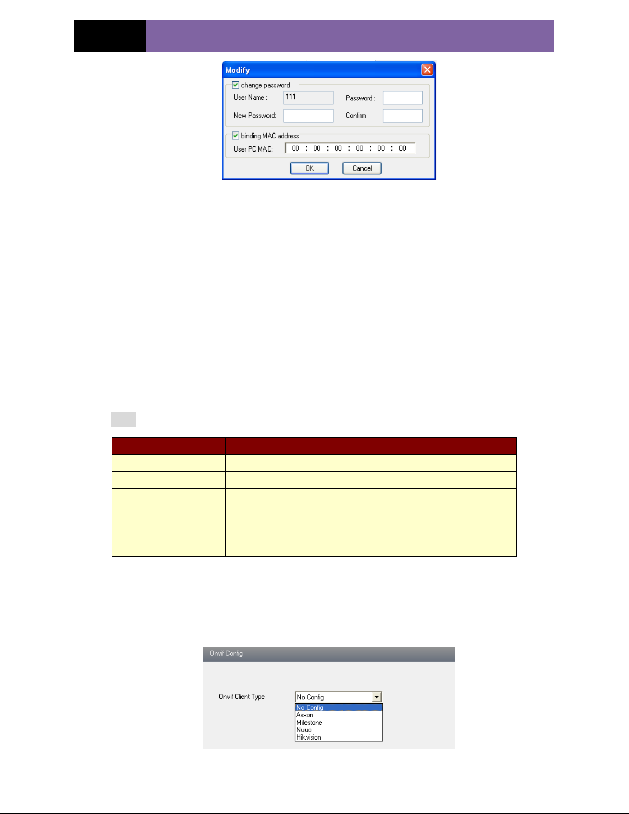
5.5.1 User Configuration
Enter into "User Configuration" interface. Refer to Fig 5-21:
Add user:
1. Clicking "Add" button pops up "Add user" dialog box. Please refer to Fig 5-22:
Fig 5-21 User Configuration Fig 5-22 Add User
Note: After bind physical address to the IP-CAM, user can access the device on this PC
in network only. If the MAC address was ““00:00:00:00:00:00” which means it can be
connected to any computers.
2. Input user name in "User Name" textbox (only letters).
3. Input characters in "Password" and "Confirm Password" textbox (letters or numbers).
4. Input the MAC address of the PC in "Binding MAC address" textbox.
5. Click “OK” button and then the new added user will display in the user list.
Modify user:
1. Select the user which needs to modify password and physical address in the user
configuration list box.
2. Clicking “Modify” button will pop up “Modify user” dialog box as shown below.
Parameter
Meaning
Server name
The name of the FTP server
Server address
The address of the FTP server
Port
The port number of the FTP server
User name
The user name of the FTP server
Password
The password of the FTP server
Path
The save path for FTP files
Page 31
Page 27
IP CAMERA USER MUANUAL
Fig 5-23 Modify User
3. Input original password of this user in the “password” text box.
4. Input new password in the “New password” and “Confirmation” text box.
5. Input computer‟s physical address which is used to access the server in the “User PC
MAC” text box.
6. Click “OK” button to modify user‟s password and binding MAC address
successfully.
Delete user:
1. Select the user which needs to delete in the user configuration list box.
2. Clicking “Delete” button will pop up a confirm dialog box. Then click “OK” to delete
the user.
Note: The default super administrator cannot be deleted.
5.5.2 Onvif Configuration
This function is mainly used for connecting our device through other companies‟
monitoring platform software, such as, Hikvision, Axxon, Milestone., etc.
Fig 5-24 Onvif Config
Parameter
Meaning
User Name
User name to operate the logon client end
User Type
Type of users, normal user, advanced user and super administrator
Binding MAC address
The MAC addresses of user access the server which should setup
according to actual MAC address of server.
Password
Password to log in the client terminal
Confirm Password
Password to log in the client terminal
Page 32
Page 28
IP CAMERA USER MUANUAL
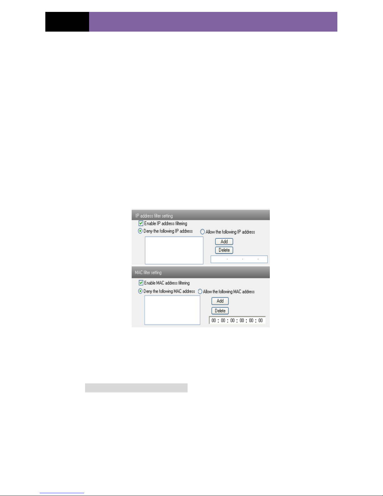
5.5.3 Security Configuration
Enter into Advanced ConfigurationSecurity Configuration to see a tab shown in Fig
5-25:
Check “Enable IP address” check box, select “Deny the following IP address”, input IP
address in the IP address list box and click “Add” button. Then this IP address will
display in the list box; the operation step of “Allow the following IP address” is the
same with “Deny the following IP address”
Select the IP address which needs to be deleted from the IP address list box and click
“delete” button to delete that IP address.
Check “Enable MAC address” check box, select “Deny the following IP address”, input
MAC address in the MAC address list box and click “Add” button. Then this MAC
address will display in the list box; the operation step of “Allow the following MAC
address” is the same with “Deny the following IP address”.
4. Select the MAC address which needs to be deleted from the MAC address list box
and click “delete” button to delete that MAC address.
5. Click "save" button to save the above setting.
Fig 5-25 Security Configuration
5.5.4 Configure Backup & Restore
Enter into Advanced configurationConfigure Backup & Restore Interface. to Fig
5-26.
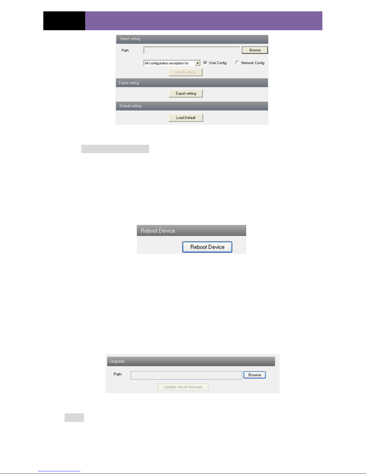
Import & Export Configuration:
User can import or export the setting information from PC or to device.
1. Click “Browse” to select save path for import or export information on PC.
2. User can import or export all setting information to PC, but those two settings “user
configuration” and “network configuration” are exceptional.
Page 33
Page 29
IP CAMERA USER MUANUAL
Fig 5-26 Backup and Restore Configuration
Default Configuration
Click “Load default” button to restore all system settings to default status.
5.5.5 Reboot Device
Enter into Advanced configuration—Reboot device to see a interface as shown in Fig
5-27:
Click “Reboot device” button to reboot the device.
Fig 5-27 Reboot device interface
5.5.6 Upgrade
Enter into Advanced Configuration—Upgrade interface shown as Fig 5-28:
1. Click “Browse” button to select the save path of the upgrade file
2. Click “Upgrade server firmware” button to start upgrading the application program
3. The device will restart automatically
4. After you successfully update the software, click “OK” button to close IE and then
re-open IE to connect IP-Cam.
Fig 5-28 Upgrade
Notice: User can‟t disconnect to PC or close the IP-CAM during upgrade.
Page 34

Page 30
IP CAMERA USER MUANUAL
6 Mobile Surveillance
This IP-CAM supports mobile surveillance by phones with Windows mobile, iPhone,
Android and Blackberry OS. Please check the operation system version of mobile
before use; and connect the IP-CAM to Internet.
6.1 Network Configuration
Access device via LAN
Step 1: Connect device via wireless router. Then checkmark DHCP both in router and
device to automatically acquire IP address or enter the IP address manually. Please enter
Main MenuInformationNetwork tab to see the IP address.
Step 2: Use WIFI function in your mobile phone to connect the wireless router.
Note: Make sure your phone network and device network are in the same network
segment on LAN.
Step 3: Add the IP address and port in the mobile phone surveillance client.
Access device via 3G network
Step 1: Set the device network. Please enter Main MenuSetupNetwork tab.
If you use PPPoE to connect device, please enable PPPoE and input username and
password received from you ISP in network tab. Then click “Apply”. You can enter
Main MenuInformationNetwork tab to see the IP address. If you want to utilize
dynamic domain name, please apply for a domain name in a DNS server supported by
the device.
If you have a static WAN IP address, please enter Main MenuSetupNetwork
tab to input your IP address, gateway and port.
If you use LAN IP address, please enter Main MenuSetupNetwork tab to
input your IP address, gateway and port and then forward IP address and port number in
virtual server setup of the router or virtual server(If you has enabled the UPnP function
in both the device and router, you can skip this step). Port forwarding setting may be
different in different routers and servers. Please refer to the router‟s manual for details.
After you forward your LAN IP address and port, please check the WAN IP address in
the router or server.
Step 2: Add the WAN IP address or domain name in mobile phone surveillance client.
6.2 By Phones with Windows Mobile OS
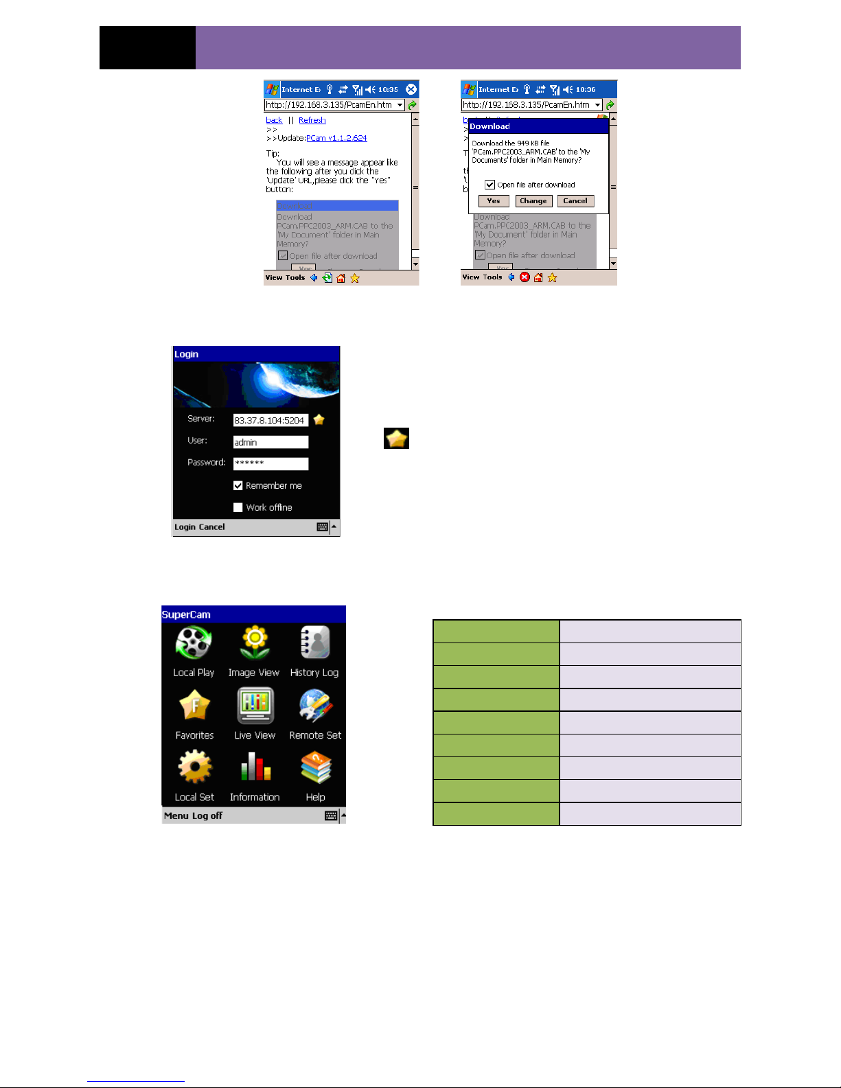
Step1: Firstly activate the network access on mobile phone and then run “Internet
Explorer”. Input the server‟s address and the connection is built up shown as below:
Step2: Click on the software name. A dialog box pops up:
Page 35
Page 31
IP CAMERA USER MUANUAL
Step3: Run this software after installed, the login interface will popup
Enter server‟s IP address (or domain name), user
name and password
Click “Remember server” to save the setting; click
button can quick input saved server address,
user name and password.
Work offline: view local record and snap.
Main interface
Live view
[Local play]
playback record file
[Image View]
View images
[History log]
Log record
[Favorites]
Server list
[Live View]
View the live
[Remote Set]
Not available
[Local Set]
Software setting
[Information]
Device information view
[Help]
Software help
Page 36
Page 32
IP CAMERA USER MUANUAL
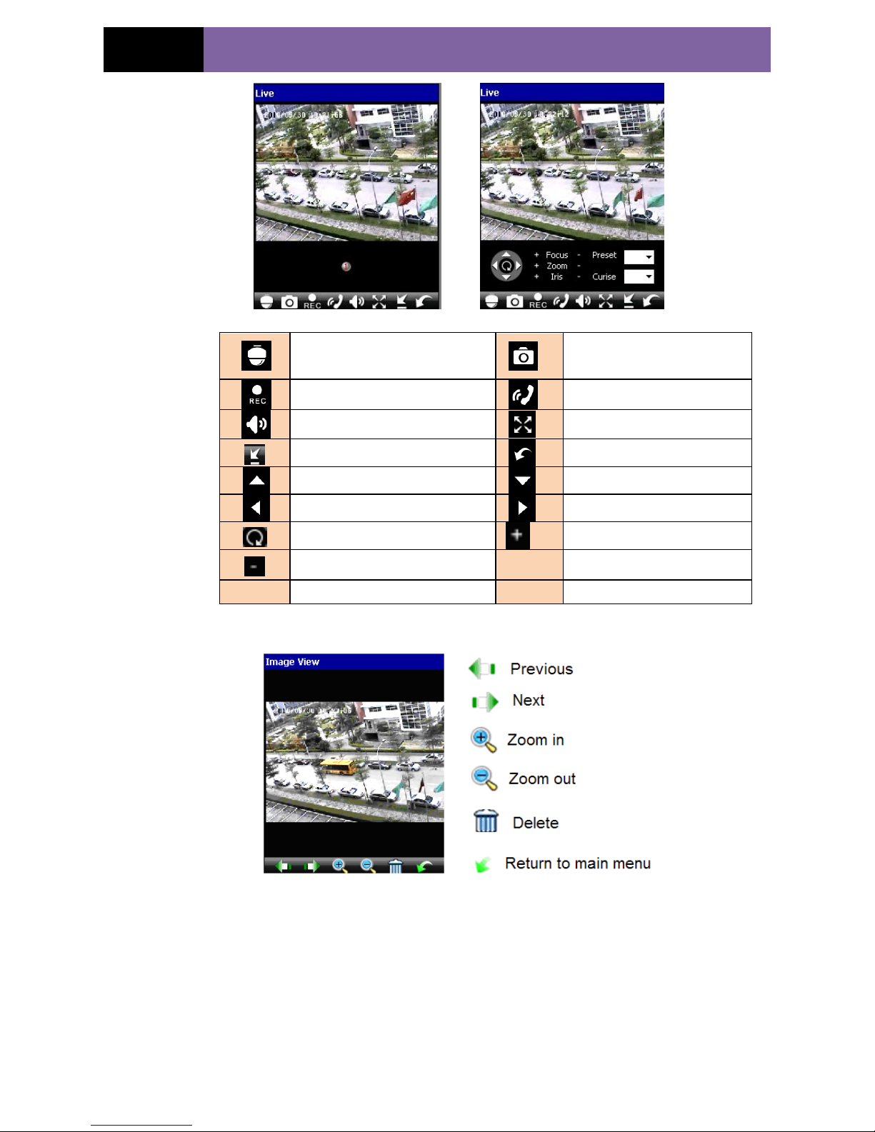
PTZ, click to switch to the
second picture.
Snap
Record
Talk
Live audio
Full screen
Hide
Return
Upward rotates the PTZ
Downward rotates the PTZ
Leftward rotates the PTZ
Rightward rotates the PTZ
Stop rotating the PTZ
Zoom in/ Focus in/ Iris Add
Zoom out/ Focus out/ Iris Sub
Preset
Select the preset point
Cruise
Set the cruise line
Image view
Record playback
Page 37
Page 33
IP CAMERA USER MUANUAL
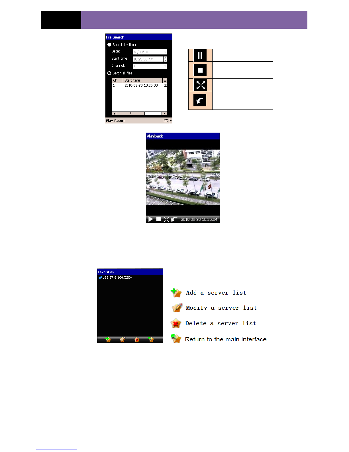
Click the record file to playback.
Server list
Configuration interface
Play/ pause
Stop
Full screen
Return to record file
interface
Page 38
Page 34
IP CAMERA USER MUANUAL
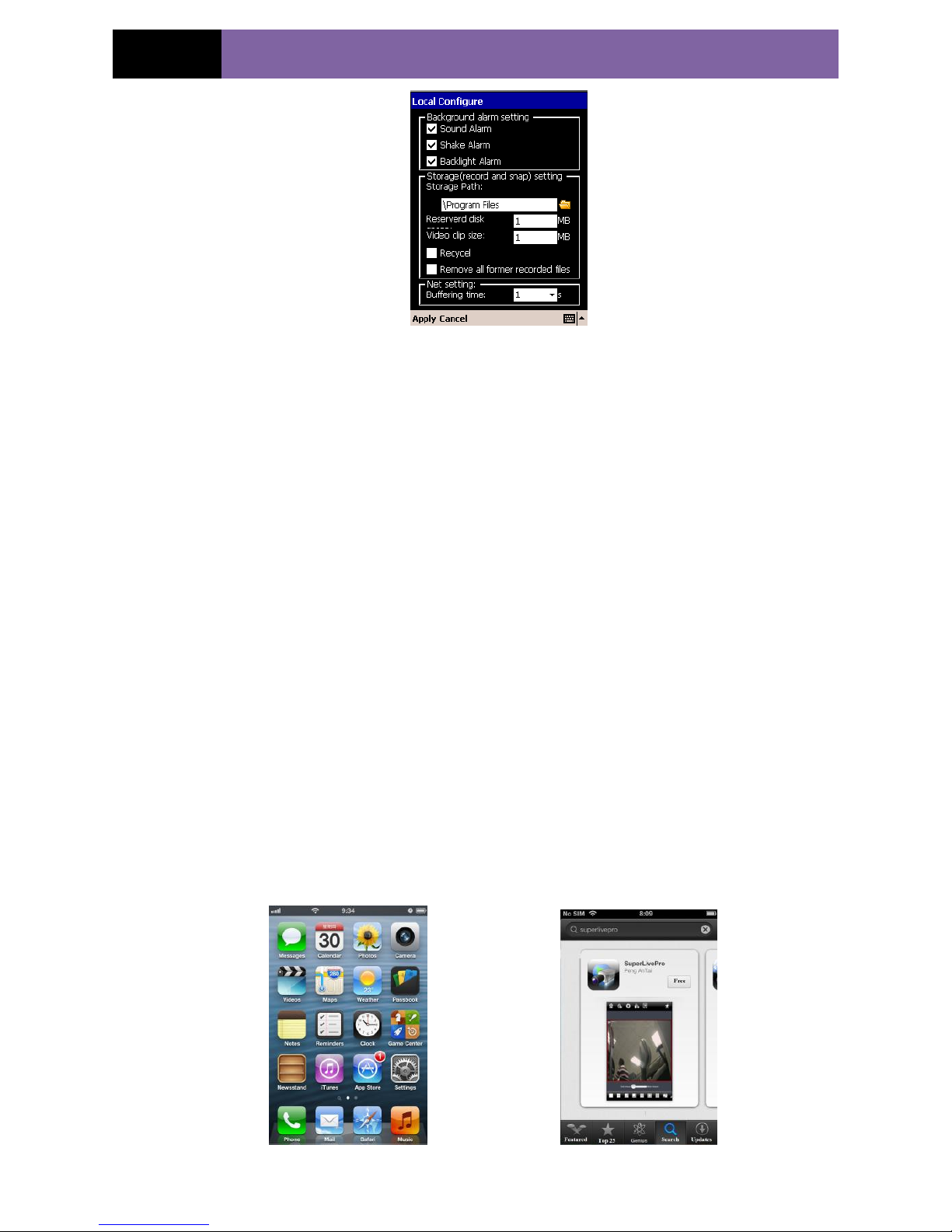
Main parameters for mobile phone video configuration.
Select Sound Alarm: When Video Loss/Sensor/Motion happens,sound alarm will be
triggered.
Select shake Alarm. When Video Loss/Sensor/Motion happens,shake alarm will be
triggered.
Select backlight Alarm: When Video Loss/Sensor/Motion happens, backlight alarm will
be triggered.
Reserved disk: Reserved SD Card disk space, when the disk space is less than setup
value, the video will be stopped.
Video clip size: Single video size. When the video size is greater than setup value,
change another video files
Recycle: continuous record.
Remove all former recorded files: delete all record files of the current device.
Buffering time: Buffering time of video display.
6.3 By Phones with iPhone OS
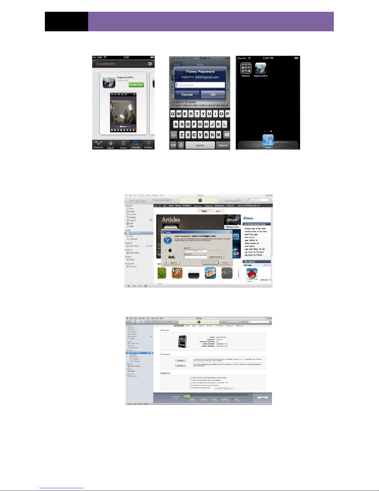
1. Install through Iphone.
Step 1: Open App Store software as shown in the figure on the left.
Step2: Search “SuperLive Pro” and click “Free” button as shown in the figure on the
right.
Step 3: Click “Install App” button as shown in the figure on the left.
Page 39
Page 35
IP CAMERA USER MUANUAL
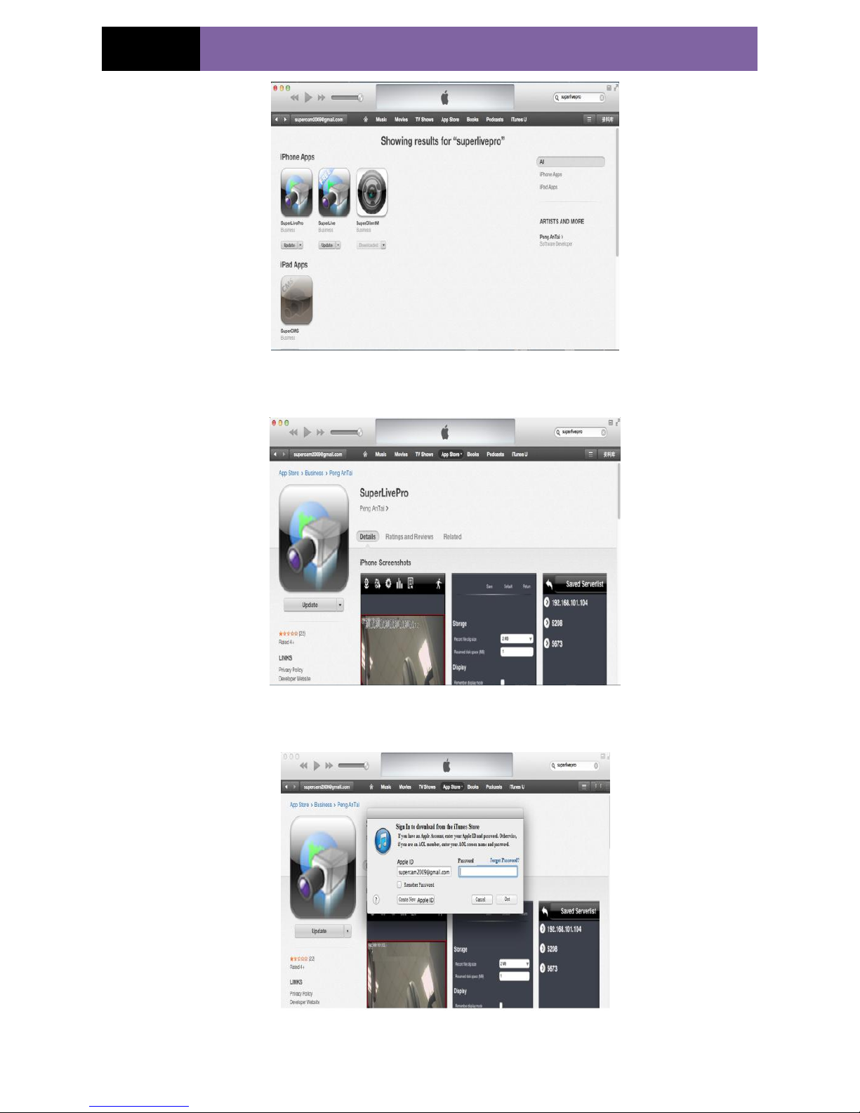
Step 4: Input iTunes Store password and then click “OK”. The software will be installed
automatically.
Install Software through PC
Step 1: Install iTunes store in PC and then login.
Step 2: Connect iPhone and PC.
Step 3: Search “SuperLivePro” and select it.
Page 40
Page 36
IP CAMERA USER MUANUAL
Step 4: Click “Download” button.
Step 5: Input username and password.
Step 6: Synchronously apply SuperLivePro software to iPhone/iPad.
Page 41
Page 37
IP CAMERA USER MUANUAL
SuperLivePro Instruction
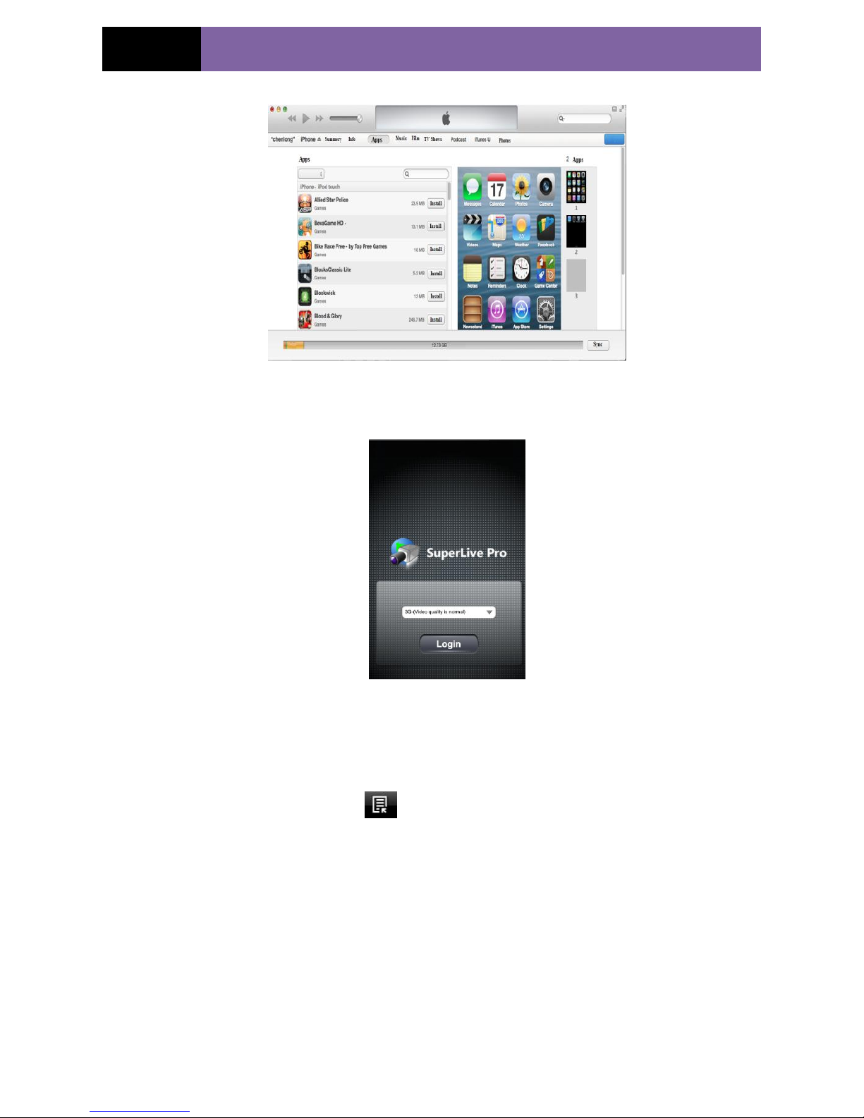
Login
Step 1: Choose network. There are two network connection ways:
3G/3G +WIFI, well video quality. This network supports main stream in single channel
playing and sub stream. The real-time image will be displayed by using sub stream.
3G-, poor video quality contrast to the above mentioned network.
Step 2: Click Login. Then click button to add device name, IP address, Port,
username and password.
Step 3: In the live interface, choose one channel and click to pop up the server list. Then
unfold the channel and choose a channel to display the live image.
Live
Page 42
Page 38
IP CAMERA USER MUANUAL
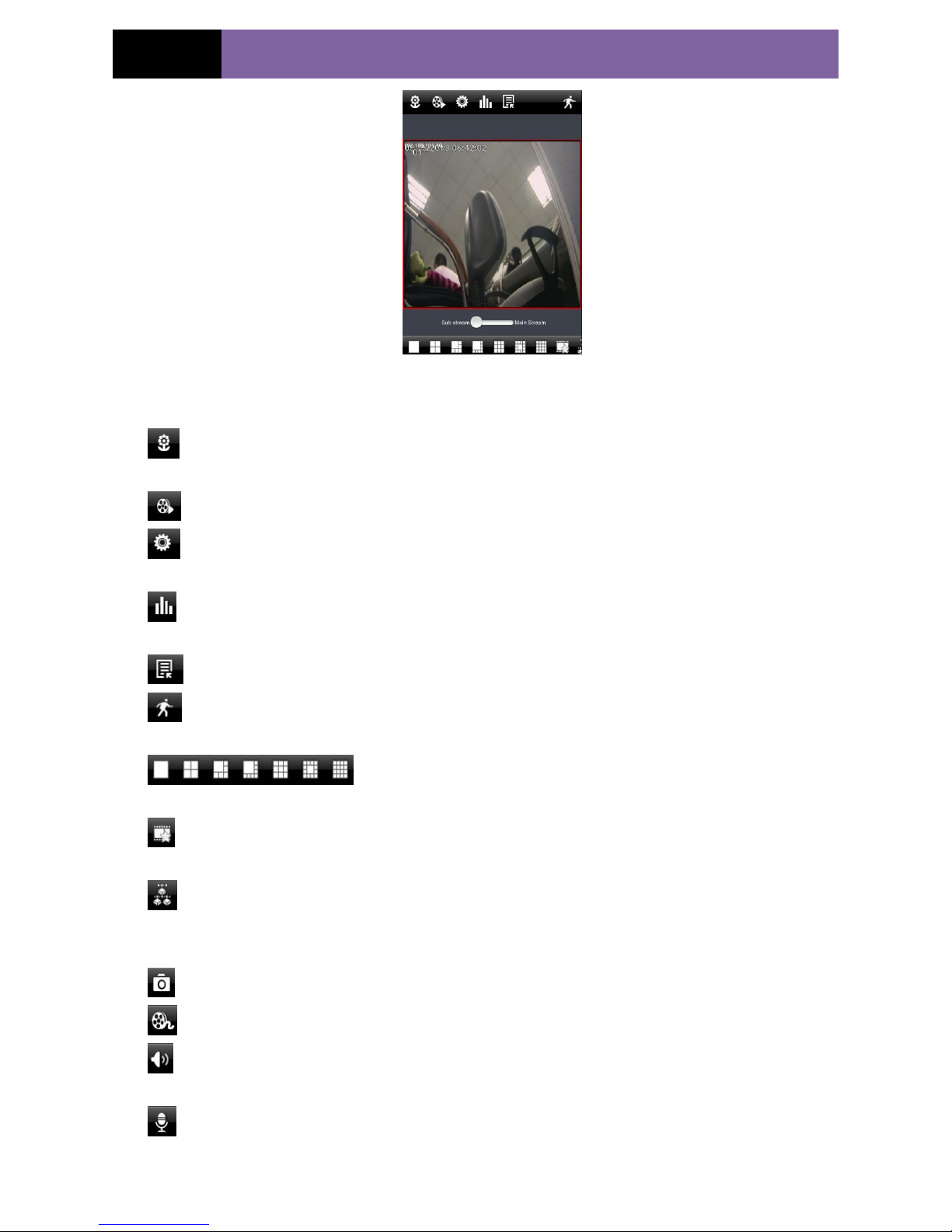
There are many buttons in live interface, such as, screen mode, favorite channel, snap,
record, open/close audio, talk, PTZ., etc.
:Image view button. The pictures snapped in the live will be checked by clicking this
button. You will view these pictures in this interface.
:Playback button. Click this button to enter into playback interface.
:Settings button. Click this button to set local configuration (Some can also support
remote configuration).
:Information button. Click this button to check lots of information including local
information, device information, network information, etc.
:Server list edition button. Click this button to add server list.
:Log off button. Click this button to return to the login interface.
:Screen mode button. You can choose 1,4,6,8,9,13 or
16 screen display mode.
:Favorite channel display button. If you save your favorite channel in the list, clicking
this button will directly play all favorite channels you have saved.
:Multiple channel choice button. You can select multiple devices at the same time and
let multiple channels to play simultaneously (The channels can not exceed the maximum
number of the current screen display mode).
:Snap button. Choose the channel and click this button to capture the channel image.
:Local record button. Choose the channel and click this button to start recording.
: Open/Close audio. Choose the channel and click this button to open/close the audio
of this channel.
:Open/Close talk. Click this button to pop up the servers which support talk function.
Select the device to start talking.
Page 43
Page 39
IP CAMERA USER MUANUAL
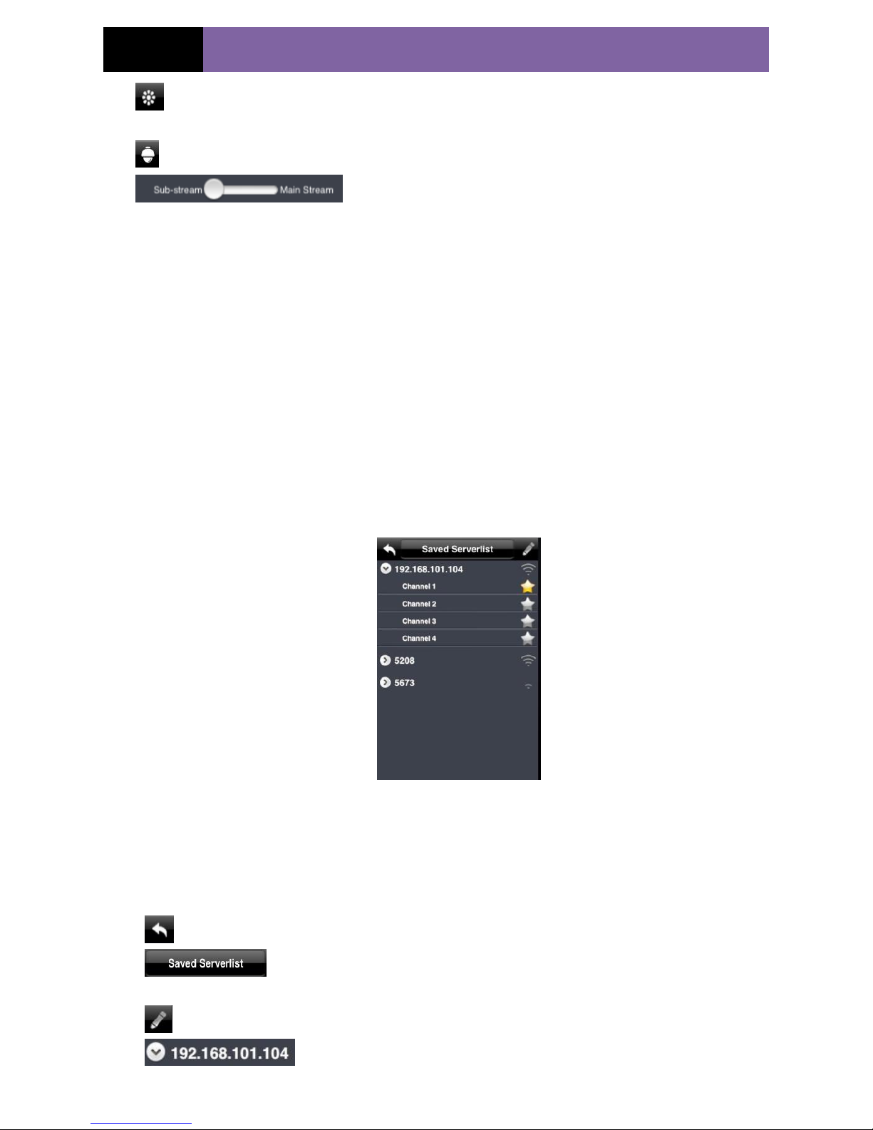
:Set video parameter button. Select the channel and click this button to set the video
parameters including brightness, hue, saturation and contrast.
:PTZ button. Click this button to pop up PTZ control panel.
: Stream switch button. If “3G/3G+/WIFI” network mode
is selected, you can switch between sub stream and main stream when only the single
channel is playing.
Other operation:
When the single channel is playing, the channel can be switched by swiping your finger
left and right.
When the single channel is playing, you can zoom in/out the image by swiping you finger
up and down
Server list
You can simultaneously connect 20 devices at most and there is a demo address for user
test.
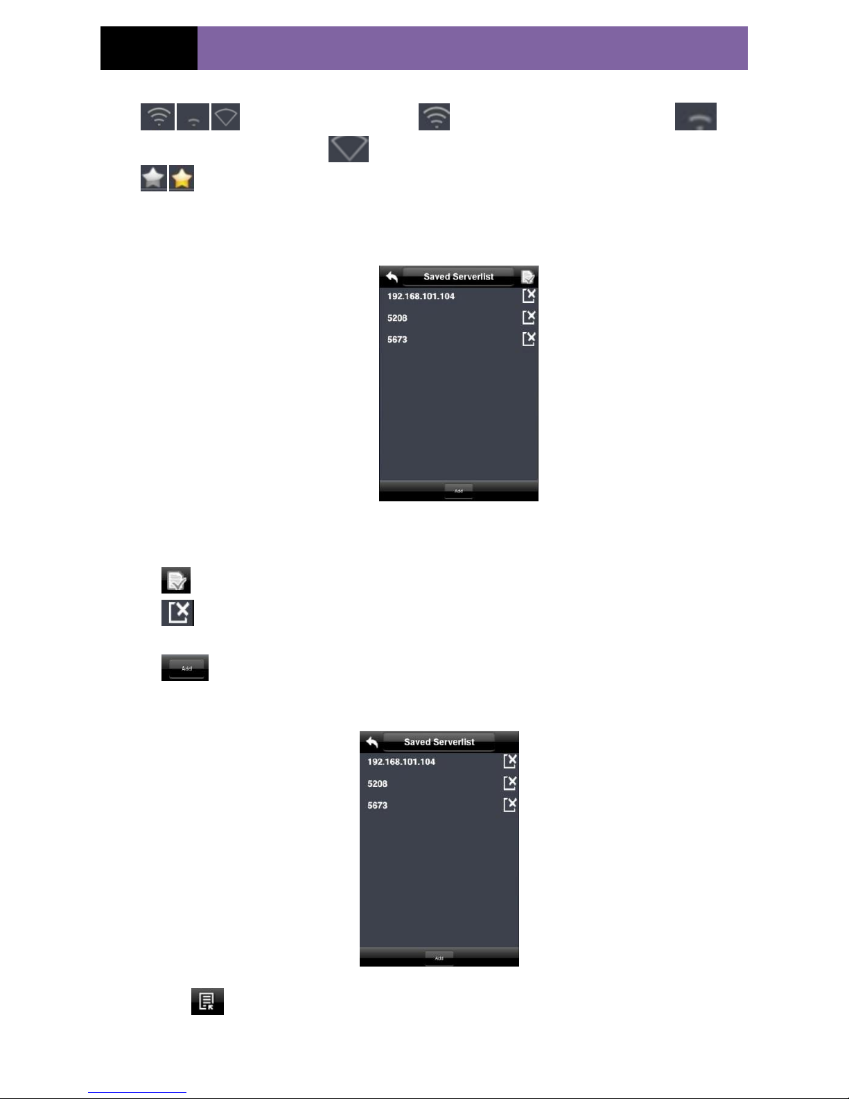
1) Saved Server List interface A
When there is no any video information playing for the channel in the live interface, click this channel to
enter the above-mentioned interface.
Where there is video displaying for the channel in the live interface, long press this channel to enter the
above-mentioned interface.
:Return button. Click this button to return to the current interface.
:The current server list name. Click this button to switch between saved server list
and favorite server list.
:Edit button. Click this button to enter edit list.
: It indicates a device. the device channel will unfold by clicking the device
Page 44
Page 40
IP CAMERA USER MUANUAL
name.
: It shows connection status. means the device has been connected.
means the devices is connecting. means the device is not connected.
: Color means the device has been saved in favorite server list. Gray means the device has not
been saved in favorite server list.
2)Saved Server List interface B
Click edition button to enter the above-mentioned interface.
:Finish button. After you finish editing, click this button to return to the saved server list interface.
:Delete button. Delete the device. If this device has been added to favorite server list, deleting it
here will also be deleted in the favorite server list.
:Add button. Add a new device.
3)Saved Server list interface C
Click button in the live interface to enter the above-mentioned interface.
Page 45
Page 41
IP CAMERA USER MUANUAL
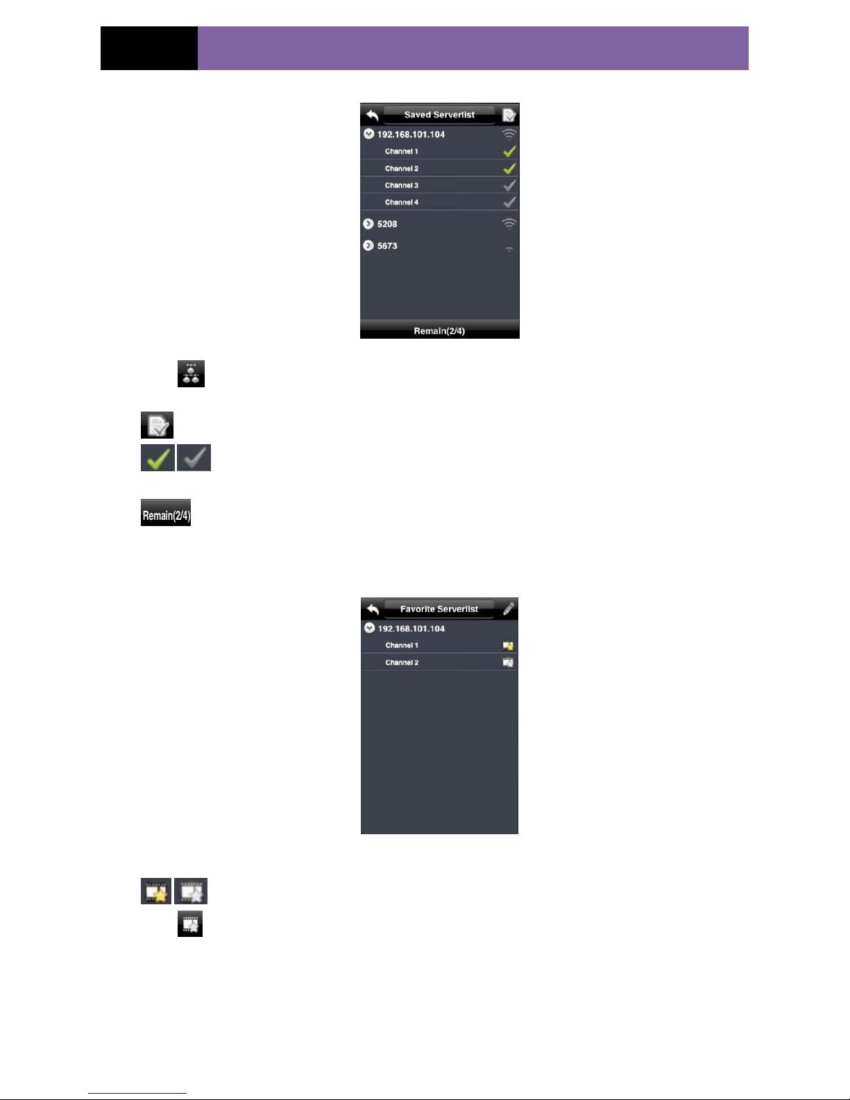
4)Multiple Channel Choice Interface
Click button to enter the above-mentioned interface.
:Click this button to return to the live interface and play the selected channel image.
:Selection button. Click the grey button to change it into color. The color button means the
channel is selected to play.
:The front number means you have already selected two channels to play. The number after two
means you can choose 4 channels at most.
Favorite Server List A
Click Saved Server list button to enter favorite server list interface.
:Color means the channel has been selected. Gray means the channel hasn‟t been selected.
Click button on the live interface to play the selected favorite channels. You can select 16 channels to
play at one time.
Favorite Server List B
Page 46
Page 42
IP CAMERA USER MUANUAL
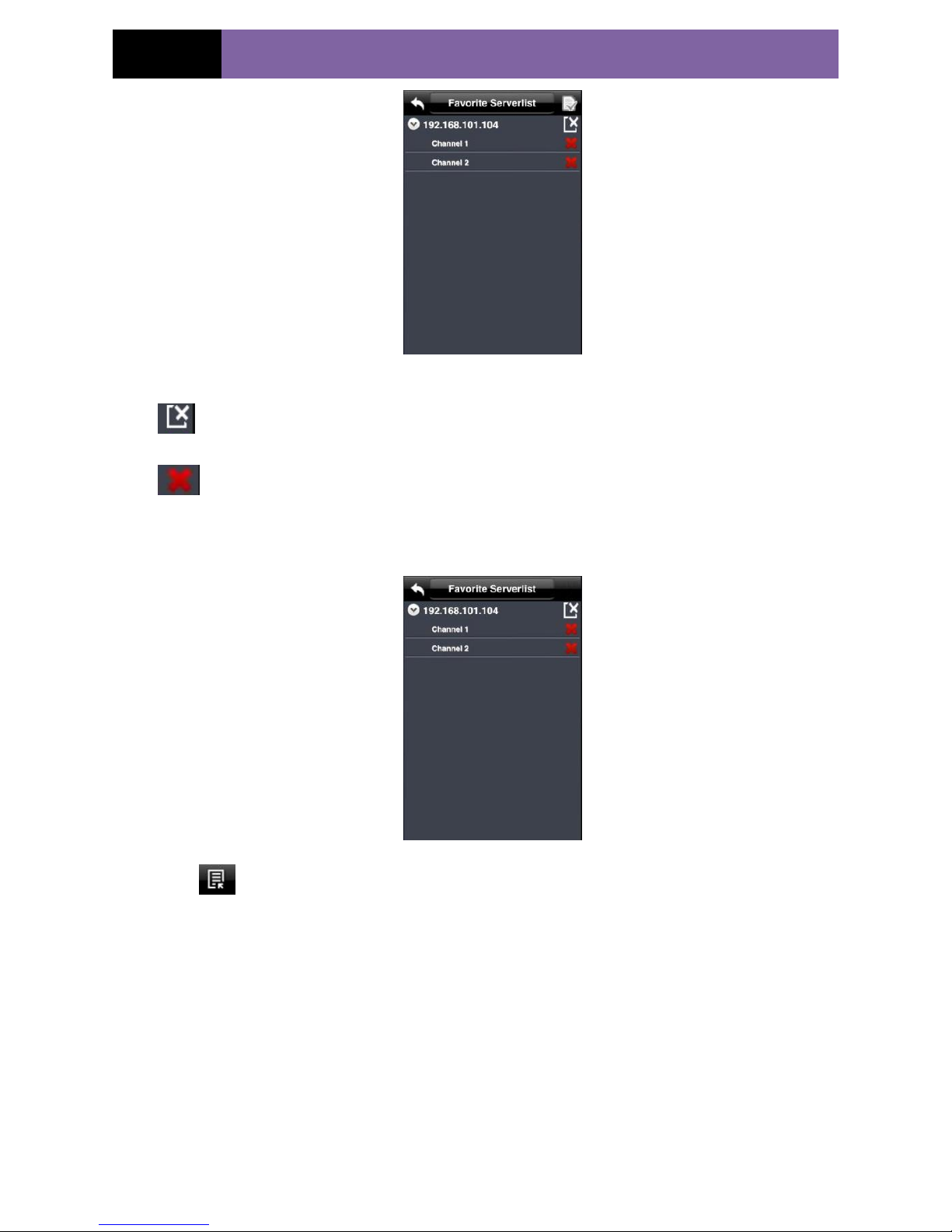
Click the edition button in the favorite server list to enter the above-mentioned interface.
:Click this button to delete the favorite device. The favorite channels under this server name will also
be deleted.
:Delete the favorite channel.
Favorite Server List C
Click button in the live interface to enter saved server list interface. Then click saved server list
button to switch to the above-mentioned interface.
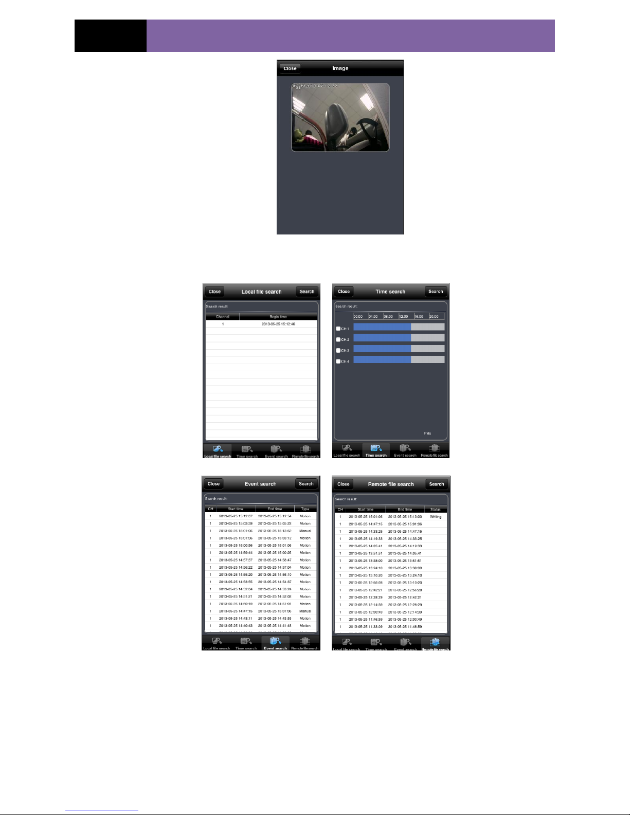
Image View
View the snapping pictures.
Page 47
Page 43
IP CAMERA USER MUANUAL
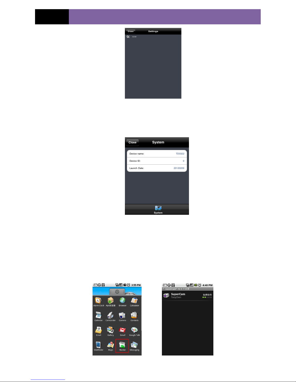
Playback Interface
(Fig 1) (Fig 2)
(Fig 3) (Fig 4)
Fig 1 is local playback; Fig 2 is remote playback by time search; Fig 3 is remote playback by event search;
Fig 4 is remote playback by file search. Only a part of devices have the latter 3 playback modes.
Settings Interface
Page 48
Page 44
IP CAMERA USER MUANUAL
This interface includes local configuration and remote configuration (only some devices support this
function). You can configure the local software or remotely set the device.
Information Interface
In this interface, you can view system information, network information and online user information.
6.4 By Phones with Android OS
Software Installation
Page 49
Page 45
IP CAMERA USER MUANUAL
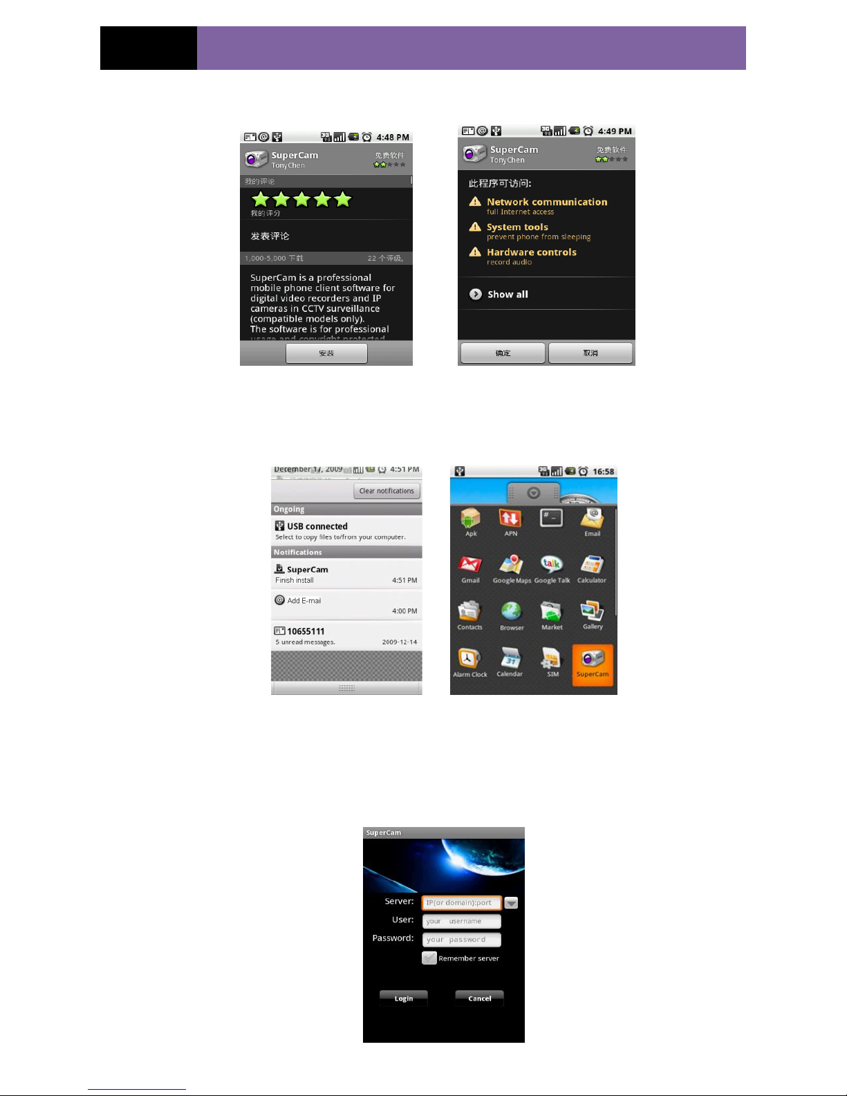
Step 1: Run Google Market program Step 2: Search ”Supercam”
Step 3: Press “Install” button Step 4: Click “OK” button
Step 5: User can view the download and install process in notifications; finished
download, the software will install automatically.
Login
Page 50
Page 46
IP CAMERA USER MUANUAL
Enter into server‟s IP address (or domain name), user‟s ID and password.
Click “Remember server” to save the setting; click button can quick input saved
server address, user name and password.
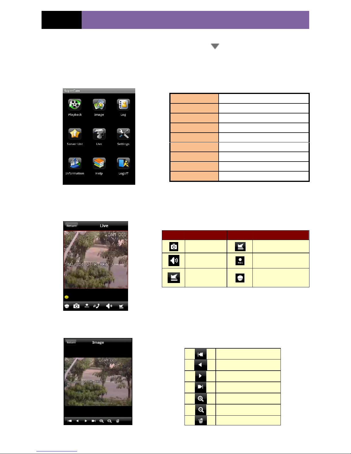
Main menu
Live view
Image view
Playback
playback record file
Image
image view
Log
log record
Server List
device list
Live
live view
Settings
software setting
Information
device information view
Help
software help center
Logoff
logoff and return to login interface
Item
Description
Item
Description
Snap
Hide
Live audio
Record
hide
PTZ, click to switch
to PTZ interface
The first picture
The previous picture
Next picture
The last picture
Zoom in
Zoom out
Delete picture
Page 51
Page 47
IP CAMERA USER MUANUAL
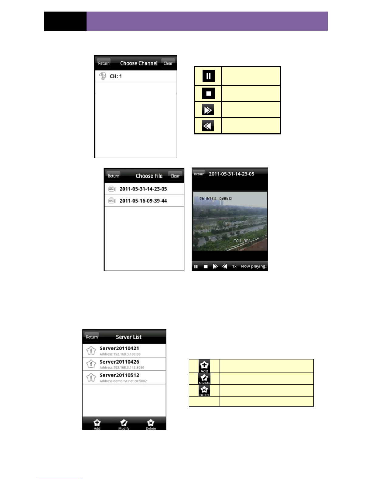
Record playback
Click Playback icon in the main menu interface to enter into the playback interface.
Then choose the channel and file. Double click the file name to playback.
Server list
Config interface
Play/pause
Stop
Fast forward
Slow playback
Add a server list
Modify a server list
Delete a server list
Return
Return to the previous interface
Page 52
Page 48
IP CAMERA USER MUANUAL
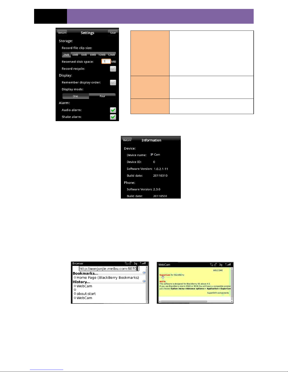
Information view
In this interface, user can view the information of device and phone, such as device
name, device ID, the software version of device or phone, etc.
6.5 By Phones with Blackberry OS
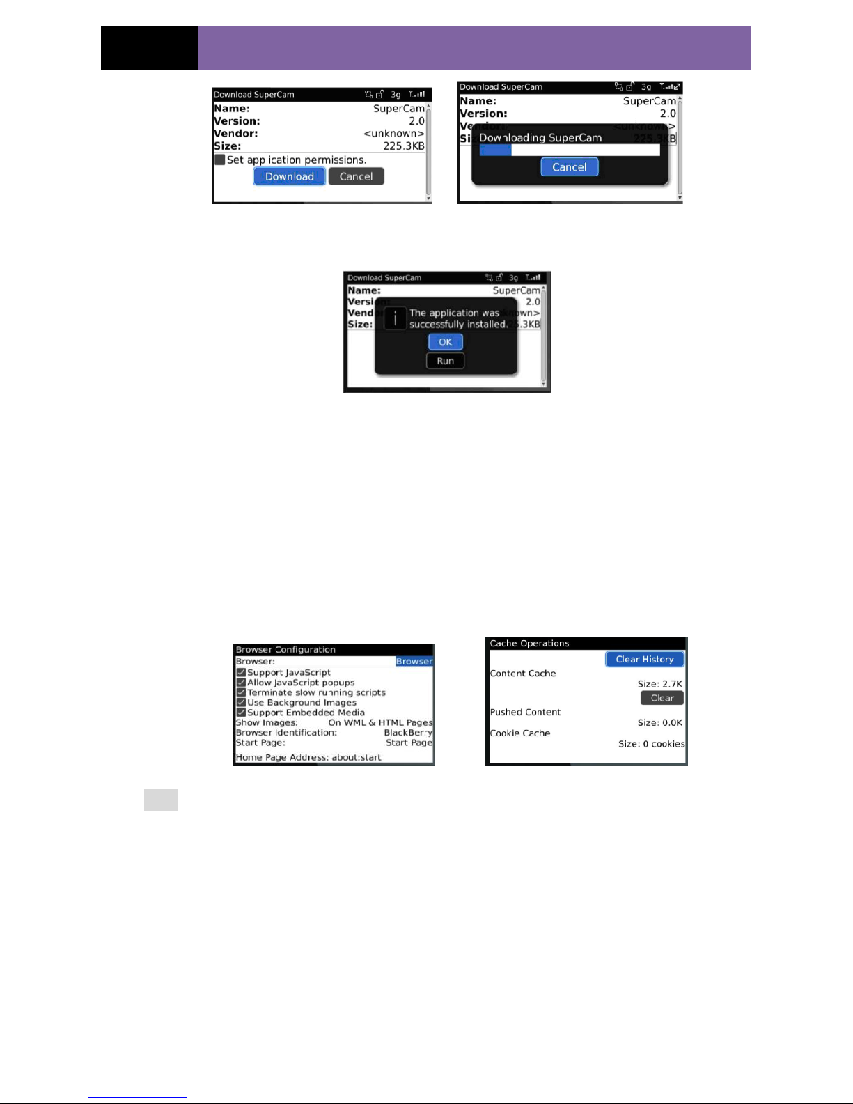
1. Open the browser of BlackBerry phone and enter sever address.
2. Click “Supercam” to link.
3. Click “Download” button on the popup interface and the download progress will be
shown.
Alarm setting
If Audio alarm is enabled, when Video
Loss/Sensor/Motion happen , sound
alarm will be triggered; If shake Alarm
is enabled, when Video
Loss/Sensor/Motion happen , shake
alarm will be triggered.
Storage setting
User can setup the relevant parameters
of mobile video. This function can be
valid only insert SD card.
Display setting
User can setup display order or display
mode.
Page 53
Page 49
IP CAMERA USER MUANUAL
4. Finished downloading, the software will be installed automatically.
Note: If the software fails to download, please check in accordance with the
following steps:
1. Check whether the network of mobile phone is normal or not
2. Check whether the IP-Cam server connect network normally or not
3. Modify the option of Browser Configuration.
(1) Enter into Menu->Option->Browser Configuration; configuration referring to the
following figure in the left.
(2) Enter into Menu->Option->Cache Operations, clear up browser cache. Refer below
picture in the right:
Note:When the user uses the Supercam software in the mobile phone with touch screen,
there will be compatible problem.
Solution: Enter into Options Menu->Advance options->Applications->Supercam and
click “Disable Compatibility” button. This problem will be solved.
Page 54
Page 50
IP CAMERA USER MUANUAL
7 Use method for IP-TOOL
Updating through IP-Tool
Note: Do not cut off power supply and internet when updating; If the device is
unable to start because of the failure of upgrade, it needs to retrofit.
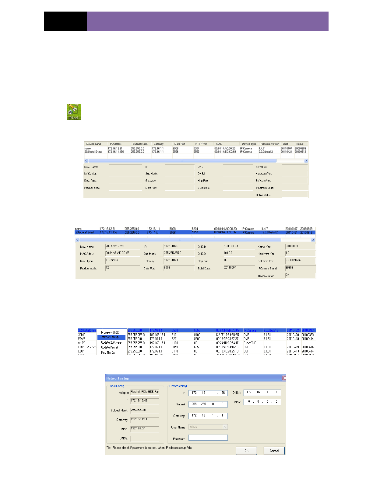
First, acquire the IP-Tool from the supplier and then double click the IP-Tool icon
to run this software. Then the device can be searched; if the device can‟t be
searched, please check whether the PC and the device connect to the network or not.
Click the device to check its detail information shown as below:
When upgrading the software and kernel, the IP address of PC and device should be at
the same network segment. If the network segment is different, user should change the
IP address by right clicking the device and then select “network setup”.
Modify IP address dialog box will appear as follows:
Page 55
Page 51
IP CAMERA USER MUANUAL
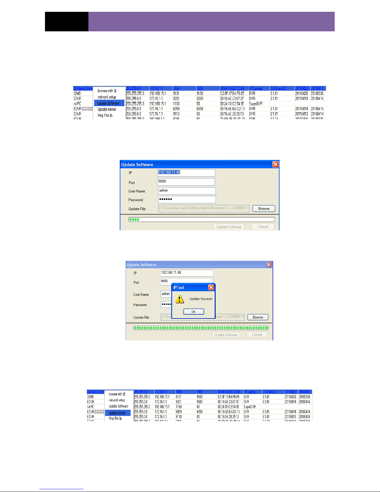
Modify IP address and click OK button to exit the dialog box, IP-Tool will display the
new IP address. Select the device; right click “Update software” as below picture
shows:
Click “Update” to start upgrading,the progress bar will display as below. When
upgrading, please do not disconnect PC and the device and make sure the power is on.
After finishing upgrading, a massage box will pop up as below:
Click OK button to exit the update dialog box, and then the device will restart
automatically. Select the device, right click it to select “Update kernel” and then a
dialog box will appear as below:
Page 56
Page 52
IP CAMERA USER MUANUAL
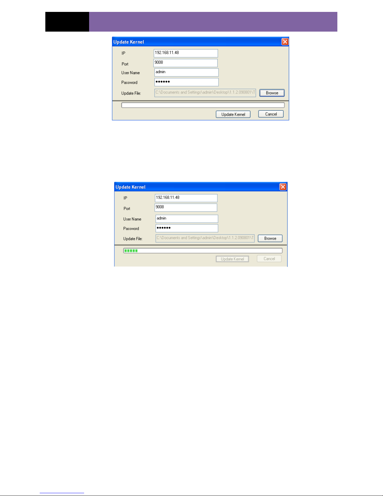
Enter into Update Kernel interface dialog box, input admin in the User name text box,
input 123456 in the Password text box, and click “Browse” to select the Update file
(mboot8180-8180), click “Update” button to start updating. When upgrading doesn‟t
disconnect PC to device, make sure the power is on. The update progress bar will
display as below:
After finishing upgrading, a message box will pop up. After a while, the device will
restart automatically.
Page 57
Page 53
IP CAMERA USER MUANUAL
8 Q & A
1. Q: Forget password
A:Joint the default line and GND line to reset.
Note: Default IP: 192.168.0.201
User name: admin
Password: 123456
2. Q:Cannot connect devices through IE browser
A: Network doesn‟t connect well. Please check the connection and make sure it
connected well.
B: IP is not available. Reset the valid IP.
C: Web port number has been revised: contact administrator to get the correct port
number.
D: Exclude the above reasons. Recover default setting by jointing the default line and
GND line.
Note: default IP: 192.168.0.201,mask number: 255.255.255.0
3. Q:IP tool cannot search devices.
A:It may be caused by the anti-virus software in your computer. Please exit it and try to
search device again.
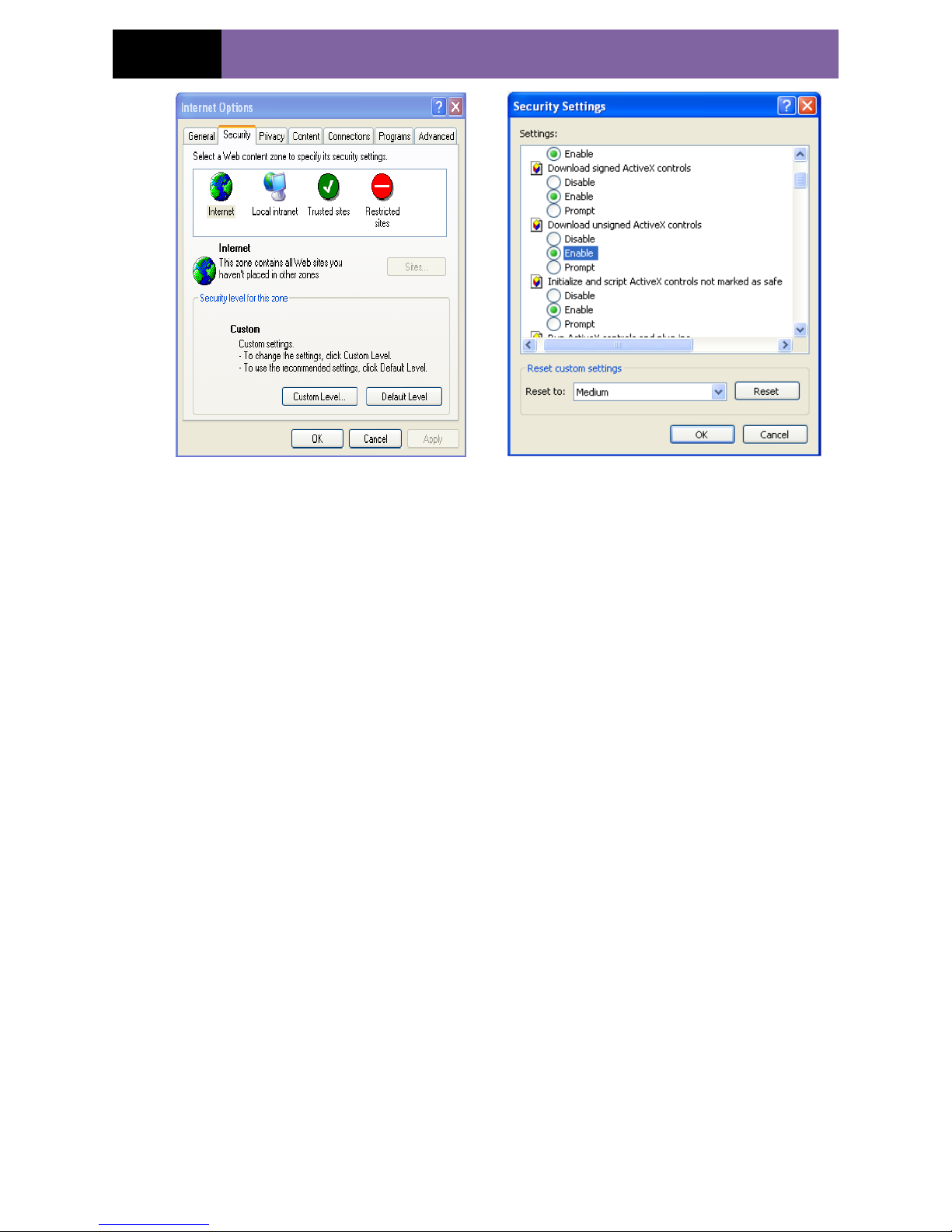
4. Q:IE Cannot download ActiveX control.
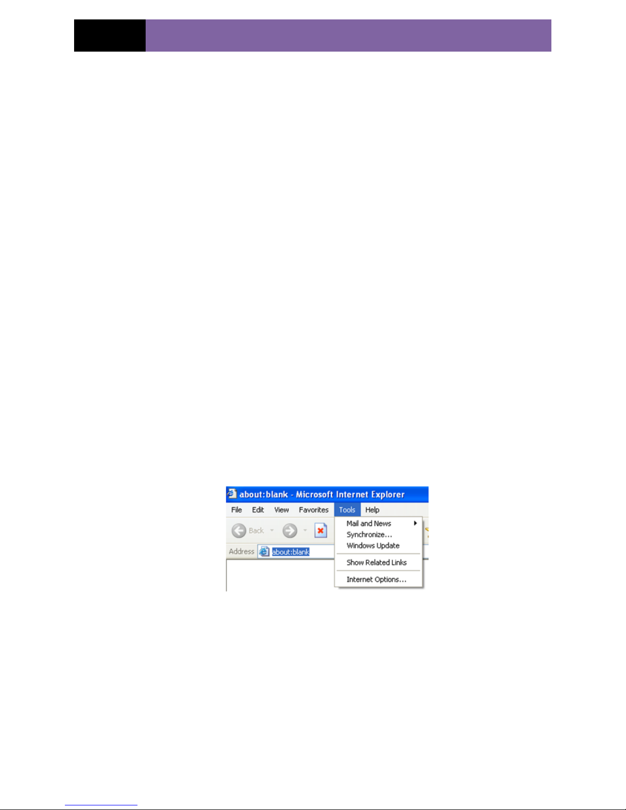
a. IE browser blocks ActiveX. Please do setup following below.
① Open IE browser. Click Tools-----Internet Options….
② select Security------Custom Level….Refer to Fig 4-1
③ Enable all the sub options under “ActiveX controls and plug-ins”. Refer to Fig 4-2
Page 58
Page 54
IP CAMERA USER MUANUAL
Fig 4-1 Fig 4-2
④ then click ok to finish setup.
b. Other plug-ins or anti-virus blocks ActiveX. Please uninstall or close them.
5. Q:No sound
A:Without connect audio input device. Please connect and try again.
B: Without enable audio function at the corresponding channel. Please check AUDIO
item to enable this function.
6. Q:Can’t connect to wireless
A: Check the statues of wireless router. Please make sure the router is open
B: Check the router and the device port. Please make the router setup is matched with
device port.
7. Q: How to do when the device is unable to start normally when upgrading?
If the device is unable to start normally when upgrading, please rename the files
suffixed with .tar as updatepack.tar and copy it to the root directory of SD card. Restart
the device and then the device will upgrade automatically from the SD card. After
finishing upgrading, the user can search the IP address of IP Cam in the IP Tool.
Page 59

Page 55
IP CAMERA USER MUANUAL
9 Specification
Model
1.3Mega Pixel Water-Proof IR Network Camera
Image Sensor
1/3”CMOS
Video Compression
H.264
Audio Compression
G711A
Image Size
1280x960
Shutter
1/25s~1/100000s
Low illumination
0 Lux (IR ON)
Lens
4mm, 6mm/8mm (optional)
Resolution
720P(1280x960/1280x720), VGA(640x480), QVGA(320x240),
QQVGA(160x120)
Stream
720P: 1024bps~6144kbps (1~30fps)
720P: 1024bps~6144kbps (1~7fps)
VGA: 256bps~2048kbps (1~30fps)
QVGA: 64kbps~512kbps(1~30fps)
QQVGA: 32kbps~384kbps(1~30fps )
Audio
MIC IN*1
Network Protocol
TCP/IP, DHCP, PPPoE, DDNS, SMTP, UPnP,RTSP,NTP
IR Range
10~15m
Protection Grade
IP66
Network Port
RJ45
Remote Surveillance
IE Browse、CMS remote control
Client Number
Max 4
Power Supply
DC12V/PoE
Working
Environment
-10°C ~50°C, 10%~90% humidity
 Loading...