

Luxaire TM9T Technical Manual
A
444561-LTG-H-1016
DESCRIPTION
These compact units employ induced combustion, reliable hot
surface ignition and high heat transfer aluminized tubular heat
exchangers. The units are factory shipped for installation in
upflow or horizontal applications and may be converted for
downflow applications.
These furnaces are designed for residential installation in a
basement, closet, alcove, attic, recreation room or garage and
TECHNICAL GUIDE
96% AFUE TWO STAGE RESIDENTIAL
GAS FURNACES MULTI-POSITION
MODELS: TM9T
NATURAL GAS
60 - 120 MBH INPUT
are also ideal for commercial applications. All units are factory
assembled, wired and tested to assure safe dependable and
economical installation and operation.
These units are Category IV, National Fuel Gas Code and may
be vented either through side wall or roof applications using
approved plastic combustion air and vent piping. Approved
plastic combustion air and vent piping include Selkirk Polyflue,
Duravent Polypro, & Centrotherm Innoflue polypropylene venting systems.
FEATURES
• Two stage heating operation includes two stage gas valve,
two stage inducer operation and 4 speed, direct drive PSC
motor blower operation. Adjustable delay timer allows two
stage operation with a single stage thermostat.
• Easily applied in upflow, horizontal left or right, or downflow
installation with minimal conversion necessary.
• Compact, easy to install, ideal height 33" tall cabinet.
• Blower-off delay for cooling SEER improvement.
• Easy access to controls to connect power/control wiring.
• Built-in, high level self diagnostics with fault code display.
• Low unit amp requirement for easy replacement application.
• All models are convertible to use propane (LP) gas.
• Electronic Hot Surface Ignition saves fuel cost with
increased dependability and reliability.
• 100% shut off main gas valve for extra safety.
• 24V, 40 VA control transformer and blower relay supplied
for add-on cooling.
• Hi-tech tubular aluminized steel primary heat exchanger
with stainless steel tube/aluminum fin secondary heat
exchanger for outstanding efficiency.
• Solid removable bottom panel allows easy conversion.
• Airflow leakage less than 1% of nominal airflow at duct
formance testing
• No knockouts to deal with, making installation easier.
Due to continuous product improvement, specifications
are subject to change without notice.
Visit us on the web at
www.upgnet.com and www.luxaire.com
dditional rating information can be found at
www.ahridirectory.org
WARRANTY SUMMARY
A 20-year limited warranty on heat exchangers in residential
applications.
A 10-year warranty on the heat exchanger in commercial
applications.
Standard 5-year limited Parts warranty.
Extended lifetime heat exchanger and 10-year limited
parts warranty when product is registered online within
90 days of purchase for replacement or closing for new
home construction.
See Limited Warranty certificate in Users Information Manual for details.
• Movable duct connector flanges for application flexibility.
• Quiet inducer operation.
• Inducer rotates for easy conversion of venting options.
• Fully supported blower assembly for easy access and
removal of blower.
• External air filters used for maximum flexibility in meeting
customers IAQ needs.
• Insulated blower compartment for thermal and acoustic
performance.
• 1/4 turn knobs provided for easy independent door
removal.
• Internal condensate trap design (patent pending) provides
condensate management options and is self priming to
prevent nuisance problems.
• Protection included from air intake, exhaust vent or condensate blockage.
• Venting applications maybe installed as either 2 pipe
sealed combustion or single pipe vent using indoor combustion air.
conditions.
per-
FOR DISTRIBUTION USE ONLY - NOT TO BE USED AT POINT OF RETAIL SALE
444561-LTG-H-1016
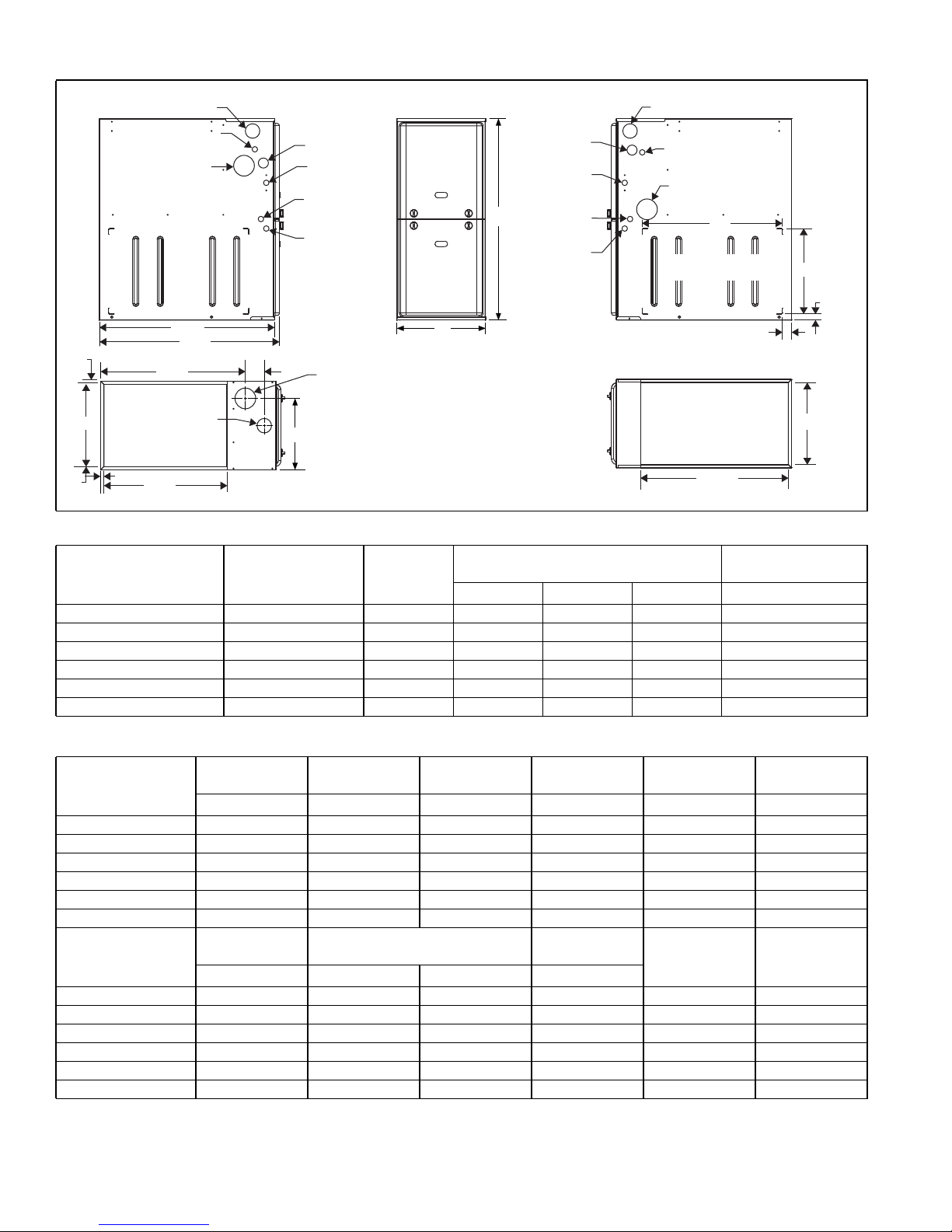
LEFT SIDE
Combustion Air Inlet
Condensate Drain
(Downflow)
Vent Outlet
28.5”
29.5”
.56”
.56”
B
.56”
23.8”
Combustion
Air Inlet
20”
SUPPLY END
Cabinet & Duct Dimensions
FRONT
Gas Pipe
Entry
Electrical
Entry
Condensate
Drain
Thermostat
Wiring
A
3”
Vent
Outlet
C
33
Gas Pipe
Entry
Electrical
Entry
Condensate
Drain
Thermostat
Wiring
RIGHT SIDE
Combustion Air Inlet
Condensate Drain
(Downflow)
Vent Outlet
23”
Optional Return Air
Cutout (Either side)
24.25”
14”
1”
1.5”
B
RETURN END
BTUH (kW)
Input
Nominal
CFM (m
3
/min)
Cabinet
Size
Cabinet Dimensions (Inches)
A B C Lbs
Approximate
Operating Weights
TM9T060B12MP11 1200 B 17 1/2 16 3/8 13 1/4 122
TM9T080B12MP11 1200 B 17 1/2 16 3/8 14 3/4 126
TM9T080C16MP11 1600 C 21 19 7/8 16 1/2 136
TM9T100C16MP11 1600 C 21 19 7/8 18 1/4 142
TM9T100C20MP11 2000 C 21 19 7/8 18 1/4 145
TM9T120D20MP11 2000 D 24 1/2 23 3/8 21 3/4 156
Ratings & Physical / Electrical Data
Input
Model
High/Low
MBH MBH Amps % °F °F
TM9T060B12MP11 60/39 58/37 10 96 35 - 65 35 - 65
TM9T080B12MP11 80/52 77/50 10 96 45 - 75 20 - 50
TM9T080C16MP11 80/52 77/50 11.5 96 45 - 75 25 - 55
TM9T100C16MP11 100/65 96/62 11.5 96 35 - 65 35 - 65
TM9T100C20MP11 100/65 96/62 17 96 45 - 75 20 - 50
TM9T120D20MP11 120/78 115/75 17 96 45 - 75 35 - 65
Max. Outlet
Model
Air Temp.
°F HP Amps In.
TM9T060B12MP11 190 0.50 7 11 x 8 15 14
TM9T080B12MP11 190 0.50 7 11 x 8 15 14
TM9T080C16MP11 190 0.75 8.8 11 x 10 15 14
TM9T100C16MP11 190 0.75 8.8 11 x 10 15 14
TM9T100C20MP11 190 1.00 14.5 11 x 11 20 12
TM9T120D20MP11 190 1.00 14.5 11 x 11 20 12
Annual Fuel Utilization Efficiency (AFUE) numbers are determined in accordance with DOE Test procedures.
Wire size and over current protection must comply with the National Electrical Code (NFPA-70-latest edition) and all local codes.
The furnace shall be installed so that the electrical components are protected from water.
Output
High/Low
Blower
Total
Unit
AFUE
Blower
Size
High Fire
Air Temp. Rise
Max.
Over-current
Protect
Low Fire
Air Temp. Rise
Min. Wire Size
(awg) @ 75 ft.
One Way
2 Johnson Controls Unitary Products
 Loading...