

Luxaire THRD18S41S1, THRD24S41S1, THRD30S41S1, THRD36S41S1, THRD42S41S1 Technical Manual
...
TECHNICAL GUIDE
COMPETITOR SERIES
SPLIT-SYSTEM
HEAT PUMPS
13 SEER – R-410A
MODELS:
THRD18 THRU 60
(1.5 THRU 5 NOMINAL TONS, 1 PHASE)
Due to continuous product improvement, specif ic a t io ns
are subject to change without notice.
Visit us on the web at www.york.com
Additional rating information can be found at
www.ahridirectory.org
LISTED
ISO 9001
Certified Quality
Management System
445073-LTG-A-0109
DESCRIPTION
The heat pump condensing unit is the outdoor part of a versatile
system of heating and air conditioning. It is designed to be custom-matched with one of UPG’s complete line of evaporator
sections, with each serving a specific function. Matching Air
Handlers are available for upflow, downflow, or horizontal applications to provide a complete system. Electric Heaters are
available, if required. Add-on coils are available for use with
upflow, downflow, or horizontal furnaces and air handlers.
WARRANTY
Single Phase Units:
5-year limited parts warranty.
5-year limited compressor warranty.
FEATURES
• QUALITY CONDENSER COILS - The coil is constructed of
copper tubing and enhanced aluminum fins for increased
efficiency and corrosion protection.
• PROTECTED COMPRESSOR - The compressor is internally protected against high pressure, temperature, and
externally by a factory installed high pressure switch. This is
accomplished by the simultaneous operation of high pressure relief valve and a temperature sensor which protects the
compressor if undesirable operating conditions occur. A liquid line filter-drier further protects the compressor.
• DURABLE FINISH - The cabinet is made of pre-painted
steel. The pre-treated galvanized steel provides a better
paint to steel bond, which resists corrosion and rust creep.
Special primer formulas and matted-textured finish insure
less fading when exposed to sunlight.
• LOWER INSTALLED COST - Installation time and costs are
reduced by easy power and control wiring connections.
Available in sweat connect models only. The unit contains
enough refrigerant for matching indoor coils and 15 feet of
interconnecting piping. The small base dimension means
less space is required on the ground or roof.
• TOP DISCHARGE - The warm air from the top mounted fan
is blown up away from the structure and any landscaping.
This allows compact location on multi-unit applications.
• LOW OPERATING SOUND LEVEL - The upward air flow
carries the normal operating noise away from the living area.
The rigid top panel effectively isolates any motor sound. Isolator mounted compressor and the rippled fins of the condenser coil muffle the normal fan motor and compressor
operating sounds.
• LOW MAINTENANCE - Long life permanently lubricated
motor-bearings need no annual servicing.
• EASY SERVICE ACCESS - Fully exposed refrigerant connections, and a single panel covering the electrical controls
make for easy servicing of the unit.
• SECURED SERVICE VALVES - Secured re-usable service
valves are provided on both the liquid and vapor sweat connections for ease of evacuating and charging.
• U.L. and C.U.L. listed - approved for outdoor application.
• Agency Listed - U.L. and C.U.L. listed - approved for outdoor application. The unit is certified in accordance with the
Unitary Small Equipment cerification program, which is
based on ARI Standard 210/240.
FOR DISTRIBUTION USE ONLY - NOT TO BE USED AT POINT OF RETAIL SALE
445073-LTG-A-0109
B
C
A
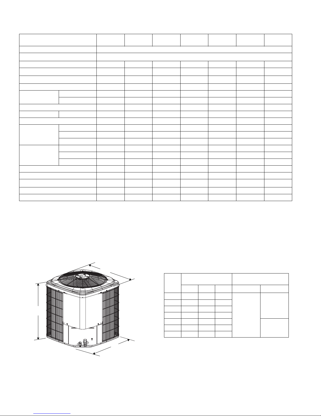
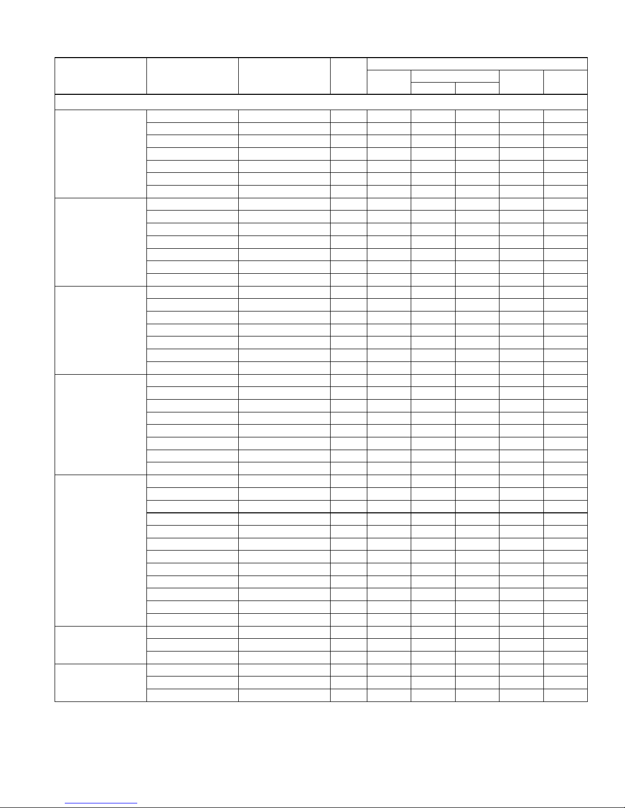
Physical and Electrical Data
MODEL
THRD18
S41S1
THRD24
S41S1
THRD30
S41S1
THRD36
S41S1
THRD42
S41S1
THRD48
S41S1
THRD60
S41S1
Unit Supply Voltage 208-230V, 1 60Hz
Normal Voltage Range
1
187 to 252
Minimum Circuit Ampacity 11.2 12.4 14.9 19.9 21.1 23.0 35.4
Max. Overcurrent Device Amps
Min. Overcurrent Device Amps
2
3
15 20 25 30 35 40 60
15 15 15 20 25 25 40
Compressor Type Recip Recip Recip Recip Recip Recip Scroll
Compressor Amps
Rated Load 8.3 9.3 11.3 14.7 15.7 17.2 27.5
Locked Rotor434354748884135
Crankcase Heater Yes Yes Yes Yes Yes Yes No
Fan Motor Amps Rated Load 0.8 0.8 0.8 1.5 1.5 1.5 1.5
Fan Diameter Inches 18 18 22 24 24 24 24
Rated HP 1/8 1/8 1/8 1/4 1/4 1/4 1/4
Fan Motor
Nominal RPM 1075 1075 1075 850 850 850 850
Nominal CFM 2000 2000 2500 3500 3500 3900 23.58
Face Area Sq. Ft. 9.3 9.3 12.8 15.7 15.7 23.6 23.6
Coil
Rows Deep 1111112
Fin / Inches 18 18 18 22 22 22 18
Liquid Line Set OD (Field Installed) 3/8 3/8 3/8 3/8 3/8 3/8 3/8
Vapor Line Set OD (Field Installed) 3/4 3/4 3/4 3/4 7/8 7/8 7/8
Unit Charge (Lbs. - Oz.)
4
5 - 6 5 - 8 7 - 8 7 - 8 8 - 8 9 - 1 13 - 1
Charge Per Foot, Oz. 0.62 0.62 0.62 0.62 0.67 0.67 0.67
Operating Weight Lbs. 145 145 176 193 198 248 290
1. Rated in accordance with ARI Standard 110, utilization range “A”.
2. Dual element fuses or HACR circuit breaker. Maximum allowable overcurrent protection.
3. Dual element fuses or HACR circuit breaker. Minimum recommended overcurrent protection.
4. The Unit Charge is correct for the outdoor unit, matched indoor coil and 15 feet of refrigerant tubing. For tubing lengths other than 15
feet, add or subtract the amount of refrigerant, using the difference in length multiplied by the per foot value.
2 Johnson Controls Unitary Products
All dimensions are in inches. They are subject to change without notice. Certified dimensions will be provided upon request.
Unit
Model
18 28
Dimensions
(Inches)
1
A
B C Liquid Vapor
23-1/2 23-1/2
24 28 23-1/2 23-1/2
30 28 29 29
36 28 34 34
42 28 34 34
60 40 34 34
1. Including Fan Guard.
Refrigerant Connection
Service Valve Size
3/4”
3/8”
7/8”48 40 34 34
445073-LTG-A-0109
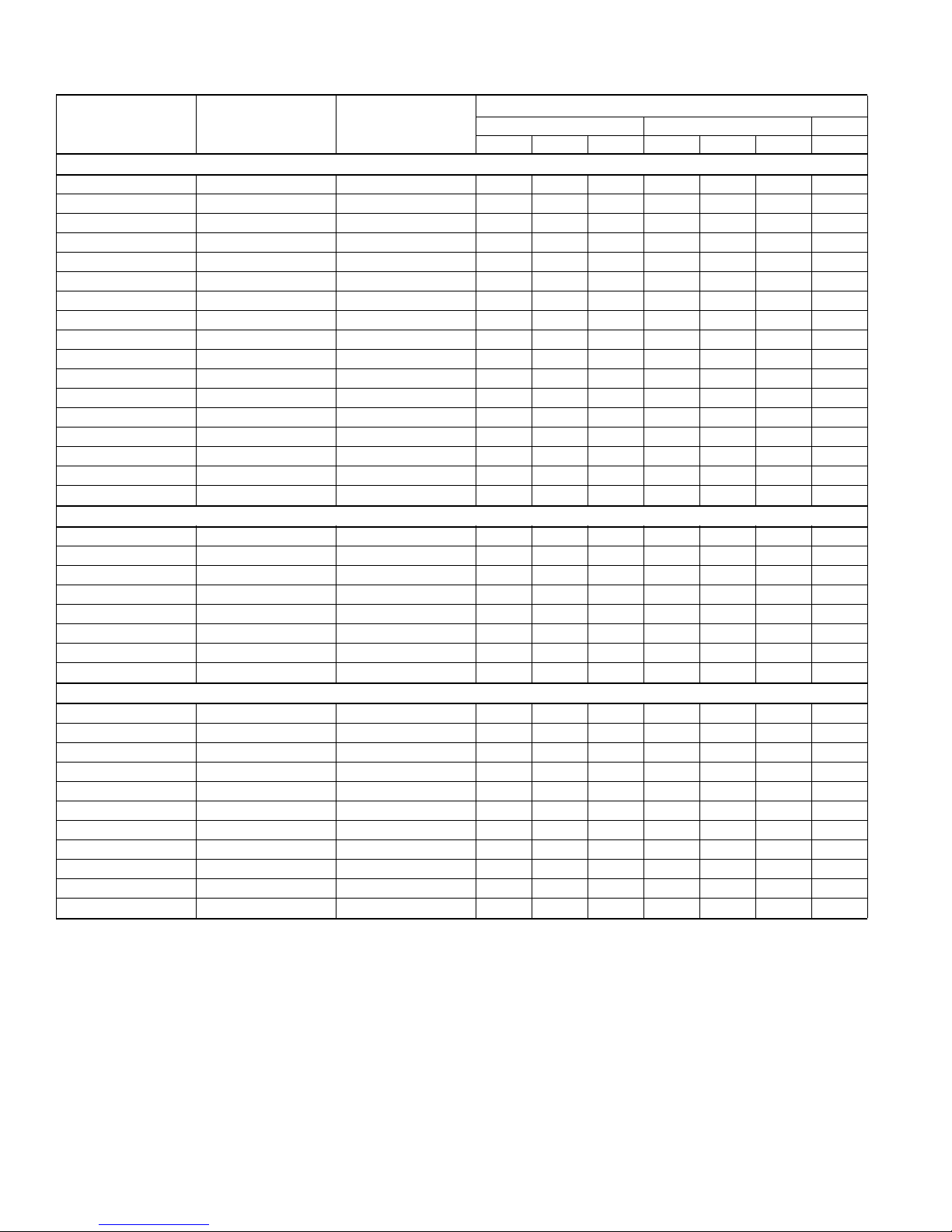
Additional R-410A Charge / Orifice Size for Various Matched Systems
Outdoor Unit THRD18S41S1 THRD24S41S1 THRD30S41S1 THRD36S41S1 THRD42S41S1 THRD48S41S1 THRD60S41S1
1,2
Required Orifice or TXV
Factory Charge, lbs-oz 5 - 6 5 - 8 7 - 8 7 - 8 8 - 8 9 - 1 13 - 1
.049/902/4F1 .055/903/4G1 .060/903/4G1 .067/904/4H1 .075/905/4J1 .078,.081/906/4K1 906/4K1
Indoor Coil
3,4
Additional Charge, Oz
FC/MC/PC/UC18A3X .049 + 0 – – – – – –
FC/MC/PC/UC18B3X .049 + 0 – – – – – –
FC/MC/PC/UC24A3X .049 + 5 .055 + 3 – – – – –
FC/MC/PC/UC24B3X .049 + 5 .055 + 3 – – – – –
FC/MC/PC/UC30A3X .049 + 5 .055 + 3 – – – – –
FC/MC/PC/UC30B3X .049 + 5 .055 + 3 – – – – –
FC/MC/PC/UC32A3X – – .060 + 0 – – – –
FC/MC/PC/UC35B3X – – .060 + 0 – – – –
FC/MC/PC/UC35C3X – – .060 + 0 – – – –
FC/MC/PC/UC37A3X – – .060 + 4 – – – –
FC/MC/PC/UC43B3X – – .060 + 4 – – – –
FC/MC/PC/UC43C3X – – .060 + 4 .067 + 6 – – –
FC/MC/PC/UC48C3X––––.075 + 0 – –
FC/MC/PC/UC48D3X––––.075 + 0 – –
FC/PC/UC60C3X ––––.075 + 2 – –
FC/MC/PC/UC60D3X––––.075 + 2 .081 + 0 –
FC/PC62D3X –––––.078 + 8TXV + 0
HC30A3X .049 + 11 .055 + 9 – – – – –
HC42C3X – – .060 + 4 .067 + 6 – – –
HC60D3X ––––.075 + 2 – –
AV24B2A .049 + 2 .055 + 0 – – – – –
AV36C2A – – .060 + 4 .067 + 6 – – –
AV48D2C ––––.075 + 2 .081 + 0 –
AV60D2C ––––.075 + 2 .081 + 0 –
F6FP018H06 .049 + 0 – – – – – –
F6FP024H06 .049 + 2 .055 + 0 – – – – –
F6FP030H06 – – .060 + 0 – – – –
F6FP036H06 – – .060 + 0 .067 + 0 – – –
F6FP042H06 ––––.075 + 0 – –
F6FP048H06 ––––.075 + 2 .081 + 0 –
F6FP060H06 –––––.078 + 8TXV + 0
FOOTNOTES:
1. For applications requiring a TXV use the correct 1TVM* series kit listed above.
2. Approved orifice shipped with outdoor unit.
3. Systems matched with furnace or air handlers not equipped with blower-off delays may require blower Time Delay Kit 2FD06700224.
4. PC coils cannot be used in downflow or horizontal applications. FC coils cannot be used in horizontal applications.
PROCEDURES:
1. Unit factory charge listed on the unit nameplate includes refrigerant for the condenser, the smallest evaporator and 15 feet of interconnecting
line tubing.
2. Verify the TXV or orifice and additional charge required for specific evaporator coil in the system using the above table.
3. Additional charge for the amount of interconnecting line tubing greater than 15 feet at the rate specified in Physical and Electrical Data Table.
4. For TXV match charge weight needs to be weighed in for specififc coil match and lineset length.
5. Permanently mark the unit nameplate with the total system charge. Total System Charge = Base Charge (as shipped) + adder for evaporator
+ adder for line set.
Johnson Controls Unitary Products 3
445073-LTG-A-0109
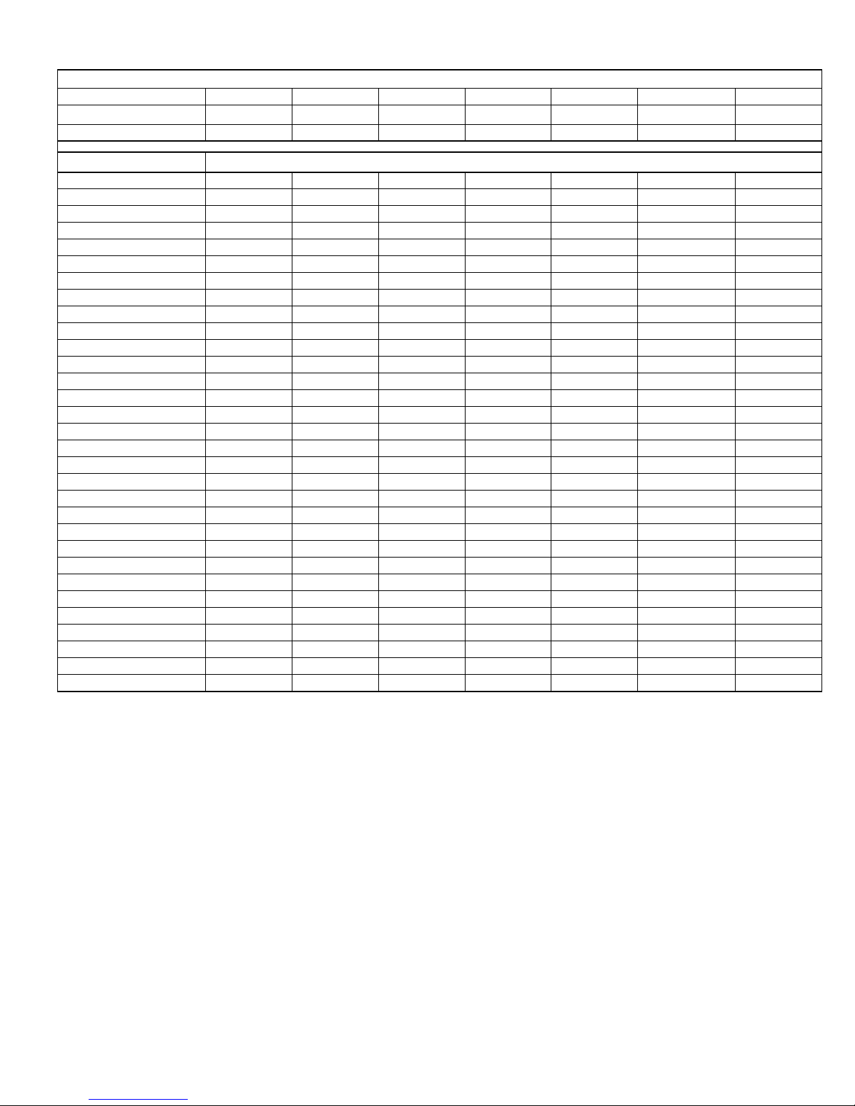
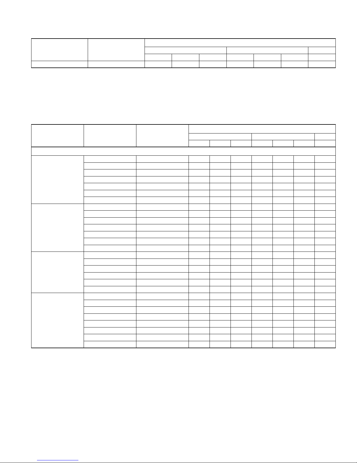
COOLING CAPACITY - With Air Handler Coils
UNIT
MODEL
AIR HANDLER
MODEL W
COIL
MODEL
1
RATED
CFM
TOTAL SENS.
13 SEER HP WITH MV - VARIABLE SPEED
THRD18S41S1 MV12B 17 FC/MC18B 655 18.0 13.5 13.00 11.20
THRD18S41S1 MV12B 17 FC/MC24B 655 18.0 13.5 13.00 11.45
THRD18S41S1 MV12B 17 FC/MC30B 655 18.0 13.5 13.00 11.45
THRD24S41S1 MV12B 17 FC/MC24B 770 23.0 17.5 13.00 11.20
THRD24S41S1 MV12B 17 FC/MC30B 770 23.0 17.5 13.00 11.20
THRD30S41S1 MV16C 21 FC/MC35C 1095 30.0 21.7 13.00 11.50
THRD30S41S1 MV12B 17 FC/MC43B 1050 30.0 21.7 13.00 11.65
THRD30S41S1 MV16C 21 FC/MC43C 1095 30.0 21.7 13.00 11.70
THRD36S41S1 MV16C 21 FC/MC35C 1215 34.2 25.0 13.00 11.20
THRD36S41S1 MV16C 21 FC/MC43C 1215 35.0 25.6 13.00 11.60
THRD42S41S1 MV16C 21 FC/MC48C 1400 40.5 31.6 13.00 11.75
THRD42S41S1 MV20D 24 FC/MC48D 1430 40.5 31.6 13.00 11.80
THRD42S41S1 MV16C 21 FC/MC60C 1400 40.5 31.1 13.00 11.85
THRD42S41S1 MV20D 24 FC/MC60D 1430 40.5 31.6 13.00 11.90
THRD48S41S1 MV20D 24 FC/MC60D 1595 47.0 35.3 13.00 11.80
THRD48S41S1 MV20D 24 FC/MC62D 1595 47.5 35.5 13.00 11.80
THRD60S41S1 MV20D 24 FC/MC62D 1800 54.5 43.0 13.00 11.20
13 SEER HP WITH AV - VARIABLE SPEED
THRD18S41S1 AV*24 17 – 595 18.0 13.5 13.00 11.20
THRD24S41S1 AV*24 17 – 815 23.6 18.0 13.00 11.30
THRD30S41S1 AV*36 21 – 1005 30.0 21.7 13.00 11.45
THRD36S41S1 AV*36 21 – 1230 35.0 25.6 13.00 11.60
THRD42S41S1 AV*48 24 – 1440 40.5 31.6 13.00 11.80
THRD42S41S1 AV*60 24 – 1400 40.5 31.6 13.00 11.75
THRD48S41S1 AV*48 24 – 1605 47.0 35.3 13.00 11.70
THRD48S41S1 AV*60 24 – 1600 47.0 35.3 13.00 11.65
13 SEER HP WITH F6FP
THRD18S41S1 F6FP18 17 – 600 18.0 13.5 13.00 11.20
THRD18S41S1 F6FP24 17 – 600 18.0 13.5 13.00 11.20
THRD24S41S1 F6FP24 17 – 800 23.6 18.0 13.00 11.30
THRD30S41S1 F6FP30 21 – 990 30.0 21.7 13.00 11.45
THRD30S41S1 F6FP36 21 – 1000 30.0 21.7 13.00 11.45
THRD36S41S1 F6FP36 21 – 1190 34.2 25.0 13.00 11.20
THRD42S41S1 F6FP42 24 – 1430 40.5 31.6 13.00 11.80
THRD42S41S1 F6FP48 24 – 1400 40.5 31.6 13.00 11.80
THRD48S41S1 F6FP48 24 – 1600 47.0 35.3 13.00 11.70
THRD48S41S1 F6FP60 24 – 1600 47.5 35.5 13.00 11.80
THRD60S41S1 F6FP60 24 – 1800 54.5 43.0 13.00 11.20
Rated in accordance with DOE test procedures (Federal Register 12-27-79 and 3-18-88) and ARI Standards 210.
Cooling MBH based on 8°F entering air temperature, 50% RH, and rated air flow.
EER (Energy Efficiency Ratio) is the total cooling output in BTU’s at 95°F outdoor ambient divided by the total electric power in watt-hours at those conditions.
SEER (Seasonal Energy Efficiency Ratio) is the total cooling output in BTU’s during a normal annual usage period for cooling divided by the total electric power
input in watt-hours during the same period.
1. MC coils available with a factory installed horizontal drain pan. See price pages for specific model number.
— = Not applicable.
COOLING
NET MBH
SEER EER
COOLING CAPACITY - Upflow, Downflow & Horizontal Furnaces and Coils
UNIT
MODEL
FURNACE**
CFM RANGE
(Min.-max.)
COIL
W
MODEL
RATED
CFM
TOTAL SENS.
THRD60S41S1 1600 - 2000 21,24 FC/MC62 1850 54.0 42.5 13.00 11.00
1. Requires a 2FD06700224 Blower Time Delay unless a standard furnace is equipped with one.
** Refer to Quick Selection Chart for specific furnace match-up.
COOLING
NET MBH
SEER
1
EER
4 Johnson Controls Unitary Products
COOLING CAPACITY - With Variable Speed Furnaces
UNIT
MODEL
THRD18S41S1
THRD24S41S1
THRD30S41S1
THRD36S41S1
THRD42S41S1
THRD48S41S1
THRD60S41S1
1. MC coils available with a factory installed horizontal drain pan. See price pages for specific model number.
2. Variable speed furnaces have B.O.D (Blower on Delay) standard.
VARIABLE SPEED
FURNACE MODEL
13 SEER HP WITH VARIABLE SPEED FURNACES
L*(8,L)C*A12 FC/MC/PC/UC24A 14 600 18.0 13.5 13.00 11.00
L*(8,L)C*B12 FC/MC/PC/UC24B 17 580 18.0 13.5 13.00 11.00
L*9C*B12 FC/MC/PC/UC24B 17 600 18.0 13.5 13.00 11.00
L*(8,L)C*A12 FC/MC/PC/UC30A 14 600 18.0 13.5 13.00 11.00
L*(8,L)C*B12 FC/MC/PC/UC30B 17 580 18.0 13.5 13.00 11.00
L*9C*B12 FC/MC/PC/UC30B 17 600 18.0 13.5 13.00 11.00
L*(8,L)C*A12 HC30 14 600 18.0 13.5 13.00 11.00
L*(8,L)C*A12 FC/MC/PC/UC24A 14 815 23.6 18.0 13.00 11.00
L*(8,L)C*B12 FC/MC/PC/UC24B 17 775 23.6 18.0 13.00 11.10
L*9C*B12 FC/MC/PC/UC24B 17 760 23.6 18.0 13.00 11.00
L*(8,L)C*A12 FC/MC/PC/UC30A 14 815 23.6 18.0 13.00 11.00
L*(8,L)C*B12 FC/MC/PC/UC30B 17 775 23.6 18.0 13.00 11.10
L*9C*B12 FC/MC/PC/UC30B 17 760 23.6 18.0 13.00 11.00
L*(8,L)C*A12 HC30 14 815 23.6 18.0 13.00 11.00
L*(8,L)C*B12 FC/MC/PC/UC43B 17 960 30.0 21.7 13.00 11.25
L*9C*B12 FC/MC/PC/UC43B 17 1000 30.0 21.7 13.00 11.15
L*(8,L)C*C16 FC/MC/PC/UC43C 21 1000 30.0 21.7 13.00 11.40
L*9C*C16 FC/MC/PC/UC43C 21 995 30.0 21.7 13.00 11.25
L*9V*C16 FC/MC/PC/UC43C 21 995 30.0 21.7 13.00 11.25
L*(8,L)C*C16 HC42 21 1000 30.0 21.7 13.00 11.40
L*9C*C16 HC42 21 995 30.0 21.7 13.00 11.25
L*(8,L)C*C16 FC/MC/PC/UC43C 21 1200 34.2 25.0 13.00 11.00
L*9C*C16 FC/MC/PC/UC43C 21 1175 34.2 25.0 13.00 11.00
L*(8,L)C*C20 FC/MC/PC/UC43C 21 1270 34.2 25.0 13.00 11.00
L*9C*C20 FC/MC/PC/UC43C 21 1270 34.2 25.0 13.00 11.00
L*(8,L)C*C16 HC42 21 1200 34.2 25.0 13.00 11.00
L*9C*C16 HC42 21 1175 34.2 25.0 13.00 11.00
L*(8,L)C*C20 HC42 21 1270 34.2 25.0 13.00 11.00
L*9C*C20 HC42 21 1270 34.2 25.0 13.00 11.00
L*(8,L)C*C16 FC/MC/PC/UC48C 21 1430 40.5 31.6 13.00 11.50
L*9C*C16 FC/MC/PC/UC48C 21 1385 40.5 31.6 13.00 11.30
L*9V*C16 FC/MC/PC/UC48C 21 1385 40.5 31.6 13.00 11.30
L*(8,L)C*C20 FC/MC/PC/UC48C 21 1370 40.5 31.6 13.00 11.60
L*9C*C20 FC/MC/PC/UC48C 21 1445 40.5 31.6 13.00 11.40
L*9C*D20 FC/MC/PC/UC48D 24 1435 40.5 31.6 13.00 11.45
L*(8,L)C*C16 FC/PC/UC60C 21 1430 40.5 31.6 13.00 11.55
L*9C*C16 FC/PC/UC60C 21 1385 40.5 31.6 13.00 11.35
L*(8,L)C*C20 FC/PC/UC60C 21 1370 40.5 31.6 13.00 11.65
L*9C*C20 FC/PC/UC60C 21 1445 40.5 31.6 13.00 11.50
L*9C*D20 FC/MC/PC/UC60D 24 1435 40.5 31.6 13.00 11.60
L*9C*D20 HC60 24 1435 40.5 31.6 13.00 11.60
L*(8,L)C*C20 FC/MC62D 24 1670 47.0 35.3 13.00 11.60
L*9C*C20 FC/MC62D 24 1605 47.0 35.3 13.00 11.50
L*9C*D20 FC/MC62D 24 1595 47.0 35.3 13.00 11.40
L*(8,L)C*C20 FC/MC62D 24 1750 54.0 42.5 13.00 11.00
L*9C*C20 FC/MC62D 24 1650 53.0 41.0 13.00 11.00
L*9C*D20 FC/MC62D 24 1615 53.5 41.5 13.00 11.00
COIL
MODEL
W
1
RATED
CFM
TOTAL SENS.
2
COOLING
Net MBH
445073-LTG-A-0109
SEER EER
Johnson Controls Unitary Products 5
445073-LTG-A-0109
HEATING PERFORMANCE - With Air Handler
UNIT
MODEL
THRD18S41S1 MV12B FC/MC18B 17.6 3.36 1.43 9.6 2.28 1.14 7.70
THRD18S41S1 MV12B FC/MC24B 17.6 3.36 1.43 9.6 2.28 1.14 7.70
THRD18S41S1 MV12B FC/MC30B 17.6 3.36 1.43 9.6 2.28 1.14 7.70
THRD24S41S1 MV12B FC/MC24B 23.0 3.74 1.66 13.4 2.62 1.32 8.20
THRD24S41S1 MV12B FC/MC30B 23.0 3.74 1.66 13.4 2.62 1.32 8.20
THRD30S41S1 MV16C FC/MC35C 27.4 3.58 2.05 14.0 2.46 1.56 8.20
THRD30S41S1 MV12B FC/MC43B 28.0 3.70 2.02 14.0 2.46 1.56 8.20
THRD30S41S1 MV16C FC/MC43C 28.0 3.70 2.02 14.0 2.46 1.56 8.20
THRD36S41S1 MV16C FC/MC43C 33.0 3.70 2.53 17.9 2.38 2.01 8.00
THRD36S41S1 MV16C FC/MC48C 33.0 3.70 2.53 17.9 2.38 2.01 8.00
THRD42S41S1 MV16C FC/MC48C 40.0 3.95 2.64 23.4 2.76 2.17 8.75
THRD42S41S1 MV20D FC/MC48D 40.0 3.95 2.64 23.4 2.76 2.17 8.75
THRD42S41S1 MV16C FC/MC60C 40.5 4.00 2.64 23.4 2.76 2.17 8.75
THRD42S41S1 MV20D FC/MC60D 40.5 4.00 2.64 23.4 2.76 2.17 8.75
THRD48S41S1 MV20D FC/MC60D 46.0 4.00 3.10 27.0 2.78 1.82 8.20
THRD48S41S1 MV20D FC/MC62D 46.0 4.00 3.10 27.0 2.78 1.82 8.20
THRD60S41S1 MV20D FC/MC62D 56.5 3.54 4.04 35.2 2.46 3.55 8.00
THRD18S41S1 AV*24 – 17.6 3.36 1.43 9.6 2.28 1.14 7.70
THRD24S41S1 AV*24 – 23.03.741.6613.42.621.328.20
THRD30S41S1 AV*36 – 27.43.582.0514.02.461.568.20
THRD36S41S1 AV*36 – 32.03.502.5317.92.382.018.00
THRD42S41S1 AV*48 – 40.53.952.6423.42.762.178.75
THRD42S41S1 AV*60 – 40.53.952.6423.42.762.178.75
THRD48S41S1 AV*48 – 46.04.003.1027.02.781.828.20
THRD48S41S1 AV*60 – 46.04.003.1027.02.781.828.20
THRD18S41S1 F6FP18 – 17.6 3.36 1.43 9.6 2.28 1.14 7.70
THRD18S41S1 F6FP24 – 17.6 3.36 1.43 9.6 2.28 1.14 7.70
THRD24S41S1 F6FP24 – 23.03.741.6613.42.621.328.20
THRD30S41S1 F6FP30 – 27.43.582.0514.02.461.568.20
THRD30S41S1 F6FP36 – 27.43.582.0514.02.461.568.20
THRD36S41S1 F6FP36 – 32.03.502.5317.92.382.018.00
THRD42S41S1 F6FP42 – 40.03.952.6423.42.762.178.75
THRD42S41S1 F6FP48 – 40.03.952.6423.42.762.178.75
THRD48S41S1 F6FP48 – 46.04.003.1027.02.781.828.20
THRD48S41S1 F6FP60 – 46.04.003.1027.02.781.828.20
THRD60S41S1 F6FP60 – 56.53.544.0435.22.463.558.00
1. Rated CFM same as for cooling.
2. Heating MBH based on ARI standards of 70° DB entering indoor air, 72% RH outdoor air with 25 feet of interconnecting piping and no
supplemental electric heat operation.
CP equals MBH output divided by (total KW input x 3.412).
HSPF (Heating Seasonal Performance Factor) is the total heating output during a normal annual usage period for heating divided by the
total electric power input during the same period.
— = Not Applicable.
AIR
HANDLER
13 SEER HP WITH MV - VARIABLE SPEED
13 SEER HP WITH AV - VARIABLE SPEED
1
COIL
MODEL
13 SEER HP WITH F6FP
MBH COP KW MBH COP KW STD
47F17FHSPF
ARI HEATING
2
6 Johnson Controls Unitary Products
445073-LTG-A-0109
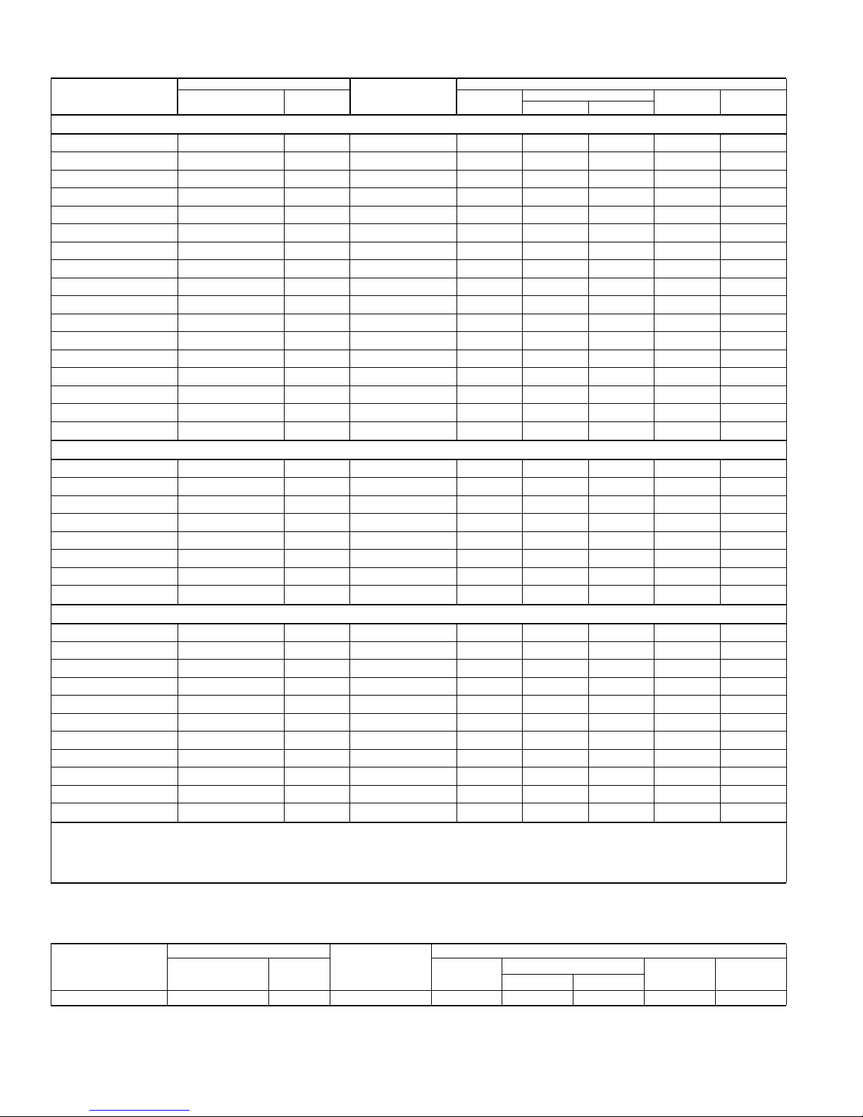
HEATING PERFORMANCE - Upflow, Downflow, and Horizontal Furnaces and Coils
UNIT
MODEL
COIL
MODEL
1
47F17F HSPF
MBH COP KW MBH COP KW STD
ARI HEATING
60S41S1 FC/MC62 56.5 3.48 4.76 35.4 2.42 4.29 8.00
1. Rated CFM same as for cooling.
2. Heating MBH based on ARI standards of 70° DB entering indoor air, 72% RH outdoor air with 25 feet of interconnecting piping and no
supplemental electric heat operation.
CP equals MBH output divided by (total KW input x 3.412).
HSPF (Heating Seasonal Performance Factor) is the total heating output during a normal annual usage period for heating divided by the
total electric power input during the same period.
— = Not Applicable.
2
HEATING CAPACITY - With Variable Speed Furnaces
UNIT
MODEL
THRD18S41S1
THRD24S41S1
THRD30S41S1
THRD36S41S1
For notes See Page 8.
VARIABLE
SPEED
FURNACE
1
COIL
MODEL
MBH COP KW MBH COP KW STD
47F17F HSPF
13 SEER HP WITH VARIABLE SPEED FURNACES
ARI HEATING
3
L*(8,L)C*A12 FC/MC/PC/UC24A 17.6 3.36 1.43 9.6 2.28 1.14 7.70
L*(8,L)C*B12 FC/MC/PC/UC24B 17.6 3.36 1.43 9.6 2.28 1.14 7.70
L*9C*B12 FC/MC/PC/UC24B 17.6 3.36 1.43 9.6 2.28 1.14 7.70
L*(8,L)C*A12 FC/MC/PC/UC30A 17.6 3.36 1.43 9.6 2.28 1.14 7.70
L*(8,L)C*B12 FC/MC/PC/UC30B 17.6 3.36 1.43 9.6 2.28 1.14 7.70
L*9C*B12 FC/MC/PC/UC30B 17.6 3.36 1.43 9.6 2.28 1.14 7.70
L*(8,L)C*A12 HC30 17.6 3.36 1.43 9.6 2.28 1.14 7.70
L*(8,L)C*A12 FC/MC/PC/UC24A 23.0 3.74 1.66 13.4 2.62 1.32 8.20
L*(8,L)C*B12 FC/MC/PC/UC24B 23.0 3.74 1.66 13.4 2.62 1.32 8.20
L*9C*B12 FC/MC/PC/UC24B 23.0 3.74 1.66 13.4 2.62 1.32 8.20
L*(8,L)C*A12 FC/MC/PC/UC30A 23.0 3.74 1.66 13.4 2.62 1.32 8.20
L*(8,L)C*B12 FC/MC/PC/UC30B 23.0 3.74 1.66 13.4 2.62 1.32 8.20
L*9C*B12 FC/MC/PC/UC30B 23.0 3.74 1.66 13.4 2.62 1.32 8.20
L*(8,L)C*A12 HC30 23.0 3.74 1.66 13.4 2.62 1.32 8.20
L*(8,L)C*B12 FC/MC/PC/UC43B 28.0 3.70 2.02 14.0 2.46 1.56 8.20
L*9C*B12 FC/MC/PC/UC43B 28.0 3.70 2.02 14.0 2.46 1.56 8.20
L*(8,L)C*C16 FC/MC/PC/UC43C 28.0 3.70 2.02 14.0 2.46 1.56 8.20
L*9C*C16 FC/MC/PC/UC43C 28.0 3.70 2.02 14.0 2.46 1.56 8.20
L*(8,L)C*C16 HC42 28.0 3.70 2.02 14.0 2.46 1.56 8.20
L*9C*C16 HC42 28.0 3.70 2.02 14.0 2.46 1.56 8.20
L*(8,L)C*C16 FC/MC/PC/UC43C 33.0 3.70 2.53 17.9 2.38 2.01 8.00
L*9C*C16 FC/MC/PC/UC43C 33.0 3.70 2.53 17.9 2.38 2.01 8.00
L*(8,L)C*C20 FC/MC/PC/UC43C 33.0 3.70 2.53 17.9 2.38 2.01 8.00
L*9C*C20 FC/MC/PC/UC43C 33.0 3.70 2.53 17.9 2.38 2.01 8.00
L*(8,L)C*C16 HC42 33.0 3.70 2.53 17.9 2.38 2.01 8.00
L*9C*C16 HC42 33.0 3.70 2.53 17.9 2.38 2.01 8.00
L*(8,L)C*C20 HC42 33.0 3.70 2.53 17.9 2.38 2.01 8.00
L*9C*C20 HC42 33.0 3.70 2.53 17.9 2.38 2.01 8.00
2
Johnson Controls Unitary Products 7

445073-LTG-A-0109
HEATING CAPACITY - With Variable Speed Furnaces (Continued)
UNIT
MODEL
THRD42S41S1
THRD48S41S1
THRD60S41S1
1. Rated CFM same as for cooling.
2. Heating MBH based on ARI standards of 70° DB entering indoor air, 72% RH outdoor air with 25 feet of interconnecting piping and no
supplemental electric heat operation.
3. Variable speed furnaces have B.O.D (Blower on Delay) standard.
CP equals MBH output divided by (total KW input x 3.412).
HSPF (Heating Seasonal Performance Factor) is the total heating output during a normal annual usage period for heating divided by the
total electric power input during the same period.
— = Not Applicable.
VARIABLE
SPEED
FURNACE
13 SEER HP WITH VARIABLE SPEED FURNACES
L*(8,L)C*C16 FC/MC/PC/UC48C 40.0 3.95 2.64 23.4 2.76 2.17 8.75
L*9C*C16 FC/MC/PC/UC48C 40.0 3.95 2.64 23.4 2.76 2.17 8.75
L*(8,L)C*C20 FC/MC/PC/UC48C 40.0 3.95 2.64 23.4 2.76 2.17 8.75
L*9C*C20 FC/MC/PC/UC48C 40.0 3.95 2.64 23.4 2.76 2.17 8.75
L*9C*D20 FC/MC/PC/UC48D 40.0 3.95 2.64 23.4 2.76 2.17 8.75
L*(8,L)C*C16 FC/PC/UC60C 40.54.002.6423.42.762.178.75
L*9C*C16 FC/PC/UC60C 40.54.002.6423.42.762.178.75
L*(8,L)C*C20 FC/PC/UC60C 40.54.002.6423.42.762.178.75
L*9C*C20 FC/PC/UC60C 40.54.002.6423.42.762.178.75
L*9C*D20 FC/MC/PC/UC60D 40.5 4.00 2.64 23.4 2.76 2.17 8.75
L*9C*D20 HC60 40.54.002.6423.42.762.178.75
L*(8,L)C*C20 FC/MC62D 46.04.003.1027.02.781.828.20
L*9C*C20 FC/MC62D 46.0 4.00 3.10 27.0 2.78 1.82 8.20
L*9C*D20 FC/MC62D 46.0 4.00 3.10 27.0 2.78 1.82 8.20
L*(8,L)C*C20 FC/MC62D 55.5 3.42 4.11 34.6 2.44 3.51 8.00
L*9C*C20 FC/MC62D 56.0 3.36 4.24 35.0 2.40 3.63 8.00
L*9C*D20 FC/MC62D 56.0 3.46 4.10 35.0 2.42 3.59 8.00
COIL
MODEL
1
47F17FHSPF
MBH COP KW MBH COP KW STD
ARI HEATING
3
2
ACCESSORIES
Refer to Price Manual for specific model numbers.
Start Assist Kit (2SA067*) - May be required on 42, 48, 60
models. Models 18, 24, 30, 36 have been factory installed.
Blower Time Delay - Available to increase efficiency when
installed. Installs on indoor section and maintains blower for
approximately one minute after cooling thermostat has been
satisfied.
Hard Start Kits - Provides required starting torque for use with
Thermal Expansion Valve Kit.
Low Temperature Cutout (2LT06700224) - Prevents heat
pump operation below -1°F ambient temperature.
Compressor Blanket - Designed to further reduce the normal
operating sound.
Add-on Fossil Fuel Control - Interface controls for use with
gas, oil furnaces and the heat pump system are available.
Thermal Expansion Valve Kit - 1TVM900 Series TXV kit used
to improve system performance.
Outdoor Thermostat (2TD06700124) - Provides additional
staging of supplemental electric heat.
Room Thermost ats - A wide selection of matching thermostats
is available to provide features required for any installation.
2H/1C, manual changeover electronic non-programmable thermostat.
3H/2C, non-programmable digital thermostat.
3H/2C, auto/manual changeover, electronic programmable, 7-
day, hardwire thermostat.
* For the most current accessory information, refer to the price
book or consult factory.
SOUND POWER RATINGS
UNIT MODEL
018 73.1 80.4
024 72.9 75.0
030 76.8 80.4
036 76.5 78.2
042 72.7 75.2
048 76.7 78.1
060 77.2 78.9
* Rated in accordance with ARI 270-95 Standards.
Cooling Heating
(dBA)*
8 Johnson Controls Unitary Products
 Loading...