

Luxaire TCJD30 THRU 76 Technical Manual
TECHNICAL GUIDE
LX SERIES
SPLIT SYSTEM AIR CONDITIONERS
13 SEER – R-410A – 3 PHASE
2.5 THRU 6.3 NOMINAL TONS
MODELS: TCJD30 THRU 76 (3)
Due to continuous product improvement, specifications
are subject to change without notice.
Visit us on the web at
www.upgnet.com and www.luxaire.com
Additional rating information can be found at:
www.ahridirectory.org
WARRANTY SUMMARY*
Standard 1-Year limited parts warranty.
Standard 5-Years limited compressor warranty.
*Does not apply to R-22 models or internet sales.
See Limited Warranty certificate in User's Information Manual for details.
®
700678-LTG-E-0415
DESCRIPTION
The 13 SEER Series unit is the outdoor part of a versatile climate system. It is designed with a matching indoor coil component from Johnson Controls Unitary Products. Available for
typical applications this climate system is supported with accessories and documents to serve specific functions.
FEATURES
• Small Footprint - Extremely lightweight with a compact foot-
print, it is a perfect fit for any application.
• Quality Condenser Coils - The coil is constructed of aluminum microchannel tubing and enhanced aluminum fins for
reduced size and increased efficiency.
• Coil Protection - Coils are protected from damage by a slotted, stamped steel coil guard and secondary polymer mesh.
• Optional Factory E-Coat - Available coated coil on select
models.
• Protected Compressor - Compressors are protected internally by a high pressure relief valve and a temperature sensor, and externally by the system high pressure switch. A
factory installed liquid line filter-drier further protects the
compressor against moisture and debris.
• Environmentally Friendly Refrigerant - The next generation refrigerant R-410A delivers environmentally friendly performance with zero ozone depletion.
• Durable Finish - The cabinet is made of G90-equivalent galvanized steel, finished in a durable titanium colored powdercoat. The coated steel wire fan guard and pre-treated,
galvanized steel chassis components resist corrosion and
rust creep.
• Lower Installed Cost - Installation time and costs are
reduced by easy power and control wiring connections. The
unit is factory charged for a 15-foot lineset. The small base
dimension means less space is required on the ground or
roof.
• T op Discharge - W arm air from the top mounted fan is blown
up, away from the structure and any landscaping. This
allows compact location on multi-unit applications.
• Low Operating Sound Levels - The upward air flow carries
the normal operating noise away from the living area. The
rigid top panel effectively isolates any motor sound. Isolator
mounted compressor and the condenser coil muffle the normal fan motor and compressor operating sounds.
• Low Maintenance - Long life, permanently lubricated motorbearings need no annual servicing.
• Easy Service Access - Fully exposed refrigerant connections and a single panel covering the electrical controls make
for easy servicing of the unit.
• Secured Service Valves - Secured, re-usable service
valves are provided on both the liquid and vapor sweat connections for ease of evacuating and charging.
• Agency Listed - Safety certified by CSA to UL 1995 / CSA
22.2. Performance certified to ANSI/AHRI Standard 210/240
in accordance with the Unitary Small Equipment certification
program.
FOR DISTRIBUTION USE ONLY - NOT TO BE USED AT POINT OF RETAIL SALE
700678-LTG-E-0415
B
C
A
Physical and Electrical Data
MODEL
TCJD30
S43S3(E)
TCJD36
S43S3(E)
TCJD42
S43S4(E)
TCJD48
S43S3(E)
TCJD60
S43S4(E)
TCJD30
S44S3(E)
TCJD36
S44S3(E)
TCJD42
S44S4(E)
TCJD48
S44S3(E)
TCJD60
S44S4(E)
Unit Supply Voltage 208-230V, 3 60Hz 460V, 3 60Hz
Normal Voltage Range
1
187 to 252 432 to 504
Minimum Circuit Ampacity 11.6 12.3 15.4 15.5 21.5 6.0 6.4 7.3 7.2 10.5
Max. Overcurrent Device Amps
Min. Overcurrent Device Amps
2
3
15 20 25 25 35 15 15 15 15 15
15 15 20 20 25 15 15 15 15 15
Compressor Type Recip Recip Recip Recip Scroll Recip Recip Recip Recip Scroll
Compressor Amps
Rated Load 8.1 8.6 11.1 11.2 16.0 4.2 4.5 5.2 5.1 7.8
Locked Rotor 63 68 68 88 110 30 34 34 44 52
Crankcase Heater No No No No No No No No No No
Factory External Discharge Muffler No No No Yes No No No No Yes No
Factory External Check Valve NoNoNoNoNoNoNoNoNoNo
Fan Motor Amps Rated Load 1.4 1.5 1.5 1.5 1.5 0.8 0.8 0.8 0.8 0.8
Fan Diameter Inches 17.5 22.0 22.0 22.0 24.0 17.5 22.0 22.0 22.0 24.0
Rated HP 1/4 1/4 1/4 1/4 1/4 1/4 1/4 1/4 1/4 1/4
Fan Motor
Nominal RPM 1100 850 850 850 850 1100 850 850 850 850
Nominal CFM 2050 3200 3050 2950 3400 2050 3200 3050 2950 3400
Face Area Sq. Ft. 9.60 13.07 14.16 14.16 18.68 9.60 13.07 14.16 14.16 18.68
Coil
Rows Deep 1111111111
Fins / Inch 23 23 23 23 23 23 23 23 23 23
Liquid Line Set OD (Field Installed) 3/8 3/8 3/8 3/8 3/8 3/8 3/8 3/8 3/8 3/8
Vapor Line Set OD (Field Installed) 3/4 3/4 7/8 7/8 7/8 3/4 3/4 7/8 7/8 7/8
Unit Charge (Lbs. - Oz.)
4
3 - 14 4 - 9 4 - 10 4 - 9 5 - 8 3 - 14 4 - 9 4 - 10 4 - 9 5 - 8
Charge Per Foot, Oz. 0.62 0.62 0.67 0.67 0.67 0.62 0.62 0.67 0.67 0.67
Operating Weight Lbs. 131 145 164 173 220 131 145 164 173 220
Models with “E” on the end of the model number have E-Coated coils.
1. Rated in accordance with AHRI Standa rd 110-2012, utilization range “A”.
2. Dual element fuses or HACR circuit breaker. Maximum allowable overcurrent protection.
3. Dual element fuses or HACR circuit breaker. Minimum recommended overcurrent protection.
4. The Unit Charge is correct for the outdoor unit, smallest matched indoor unit, and 15 feet of refrigerant tubing. For tubing lengths other t han 15 feet, add or subtract
the amount of refrigerant, using the difference in actual lin eset length (not equivalent length) multiplied by the per foot val ue.
2 Johnson Controls Unitary Products
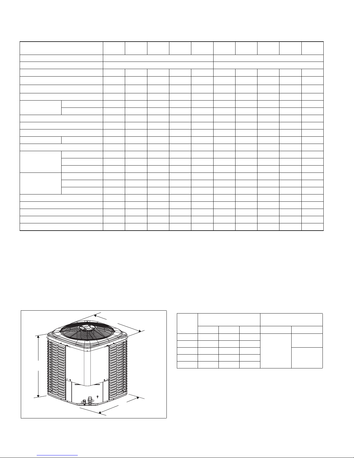
Unit
Model
Dimensions
(Inches)
A B C Liquid Vapor
Refrigerant Connection
Service Valve Size
30 28-1/4 24 24
36 28-1/4 29-1/2 29-1/2
42 30-1/4 29-1/2 29-1/2
3/8
60 32-1/4 34 34
All dimensions are in inches and are subject to chang e without notice.
Overall height is from bottom of base pan to top of fan guard.
Overall length and width include screw heads.
3/4
7/848 30-1/4 29-1/2 29-1/2
700678-LTG-E-0415
System Charge for Various Matched Systems
Outdoor Unit TCJD30S4(3,4)S3(E) TCJD36S4(3,4)S3(E) TCJD42S4(3,4)S4(E) TCJD48S4(3,4)S3(E) TCJD60S4(3,4)S4(E)
Required Orifice or TXV
1,2
0.061/4F1 0.065/4G1 0.073/4G1 0.073/4H1 0.084/4J1
Indoor Unit
3,4,5
Additional Charge, oz
AHE30B 0––––
AHE36C 20–––
AHE42D – 8 10 – –
AHE48D ––90–
AHE60D – – 14 – 4
AHR30B 0––––
AHR36B 20–––
AHR42C – 8 10 – –
AHR48D ––90–
AHR60D – – 15 – 4
AHV30B 0––––
AHV36C 60–––
AHV42D 18 10 10 – –
AHV48D – 10 9 3 –
AHV60D – – 13 8 4
FC/MC/PC32 0––––
FC/MC/PC35 0––––
FC/MC/PC37 20–––
FC/MC/PC43 200––
FC/MC/PC48 – 8 10 4 –
FC/MC/PC60 ––900
FC/MC62 ––14– 4
FC64 – – 23 – 11
UC48 –844–
UC60 ––900
Some of the combinations shown in the above System Charge table require Advanced Main Air Circulating Fan indoor product. For approved coil
only matches, please see the “COOLING CAPACITY - Upflow, Downflow & Horizontal Furnaces and Coils” table.
FOOTNOTES:
1. For applications requiring a TXV use S1-1TVM*** series kit.
2. Approved orifice(s) shipped with outdoor unit.
3. Systems matched with furnaces or air handlers not equipped with blower-off delays may require blower Time Delay Kit S1-2FD06700224.
4. PC coils cannot be used in downflow or horizontal applications. FC coils cannot be used in horizontal applications.
5. Refer to Cooling Performance Data tables for actual system performance for specified system matches.
PROCEDURES:
1. Unit factory charge listed on the unit nameplate includes refrigerant f or the outdoor unit, the smallest matched indoor unit, and 15 feet of interconnecting line tubing.
2. Verify the TXV or orifice and additiona l charge required for specific matched indoor unit in the system using the above table.
3. Add additional charge for the amount of interconnecting line tubing great er than 15 feet at the rate specified in Physical and Electrical Data Table.
4. For indoor matches requiring additional charge, the refrigerant needs to be weighed in for specific matched indoor unit and actual lineset length.
5. Permanently mark the unit nameplate with the total system charge. Total System Charge = Base Charge (as shipped) + charge adder for matched indoor unit +
charge adder for actual lineset length.
Johnson Controls Unitary Products 3
700678-LTG-E-0415
B
C
A
Physical and Electrical Data
MODEL
Unit Supply Voltage 208-230V, 3 60Hz 460V, 3 60Hz
Normal Voltage Range
Minimum Circuit Ampacity
Max. Overcurrent Device Amps
Min. Overcurrent Device Amps
Compressor Type
Compressor Amps
Crankcase Heater
Factory External Discharge Muffler
Factory External Check Valve
Fan Motor Amps Rated Load
Fan Diameter Inches
Fan Motor
Coil
Liquid Line Set OD (Field Installed)
Vapor Line Set OD (Field Installed)
Unit Charge (Lbs. - Oz.)
Charge Per Foot, Oz. 1.18 1.18
Operating Weight Lbs. 247 247
1. Rated in accordance with AHRI Standard 110-2012, utilization range “A”.
2. Dual element fuses or HACR circuit breaker. Maximum allowable overcurrent
protection.
3. Dual element fuses or HACR circuit breaker. Minimum recommended overcur rent protection.
4. The Unit Charge is correct for the outdoor unit, smallest matched indoor unit,
and 15 feet of refrigerant tubing. For tubing lengths other than 15 feet, add or
subtract the amount of refrigerant, using the difference in actual lineset length
(not equivalent length) multiplied by the per foot value.
1
3
Rated Load
Locked Rotor
Rated HP
Nominal RPM
Nominal CFM
Face Area Sq. Ft.
Rows Deep
Fins / Inch
4
TCJD76S43S3 TCJD76S44S3
187 to 252 432 to 504
30.2 14.4
2
50 25
35 15
Scroll Scroll
22.4 10.6
149 75
No No
No No
No No
2.2 1.2
22 22
1/3 1/3
1100 1100
4300 4300
23.75 23.75
1 1
23 23
1/2 1/2
1-1/8 1-1/8
10 - 4 10 - 12
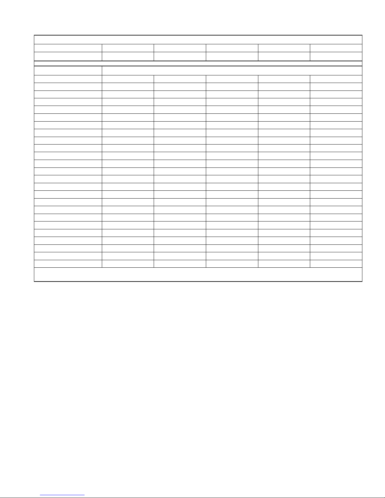
System Charge for Various Matched Systems
Outdoor Unit TCJD76S4(3,4)S3
Indoor Coil
1
NH-07 0
Some of the combinations shown in the above System Charge table
require Advanced Main Air Circulating Fan indoor product. For
approved coil only matches, please see the “COOLING CAPACITY Upflow, Downflow & Horizontal Furnaces and Coils” table.
FOOTNOTES:
1. Refer to Cooling Performance Data tables for actua l system performance for
specified system matches.
PROCEDURES:
1. Unit factory charge listed on the unit nameplate includes refrigerant for the
outdoor unit, the smallest matched indoor unit, and 15 feet of i nterconnecting line tubing.
2. The required TXV is factory mounted on the Indoor Unit.
3. Add additional charge for the amount of interconnecting line tubing greater
than 15 feet at the rate specified in Physical and Electrical Data Table.
4. For indoor matches requiring additional charge, the refrigerant needs to be
weighed in for specific matched indoor unit and actual lineset length.
5. Permanently mark the unit nameplate with the total system charge. Total
System Charge = Base Charge (as shipped) + charge adder for matched
indoor unit + charge adder for actual lineset length.
Additional Charge, oz
4 Johnson Controls Unitary Products
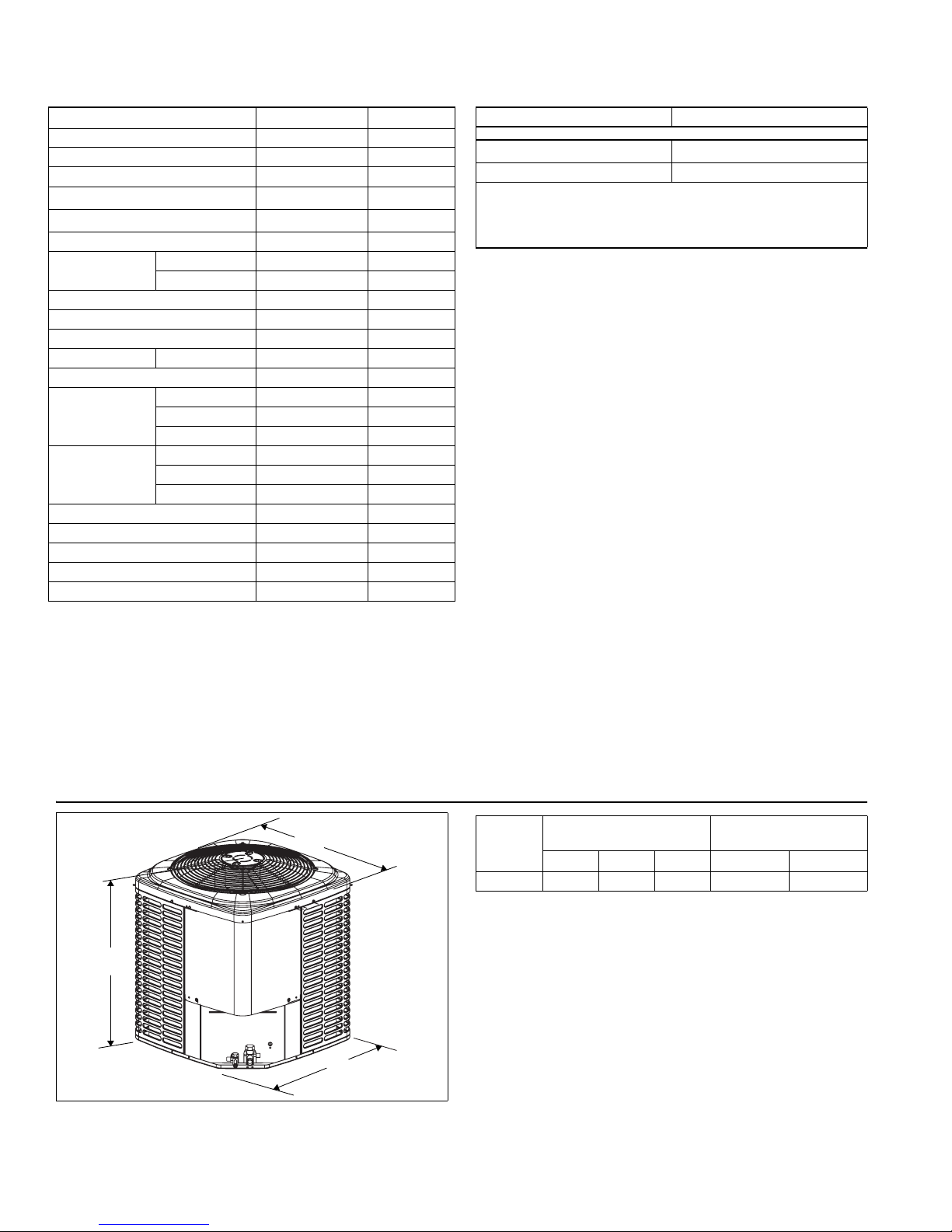
Unit
Model
Dimensions
(Inches)
A B C Liquid Vapor
Refrigerant Connection
Service Valve Size
76 40-1/4 34 34 1/2 1-1/8
All dimensions are in inches and are subject to chang e without notice.
Overall height is from bottom of base pan to top of fan guard.
Overall length and width include screw heads.
COOLING CAPACITY - With Air Handler Coils
UNIT
MODEL
TCJD30S4(3,4)S3(E)
TCJD36S4(3,4)S3(E)
TCJD42S4(3,4)S4(E)
For Notes See Page 6.
AIR HANDLER
MODEL WIDTH
13 SEER AC WITH AIR HANDLERS
AHE30B 17.5 – 985 29.4 21.4 14.00 11.75
AHE36C 21.0 – 1000 30.2 22.0 14.75 12.25
AHR30B 17.5 – 1095 29.4 22.2 13.00 11.00
AHR36B 17.5 – 1060 29.8 22.0 13.00 11.00
AHV30B 17.5 – 1000 29.0 21.3 13.50 11.50
AHV36C 21.0 – 895 29.0 20.9 14.50 12.00
AHV42D 24.5 – 1080 30.0 22.8 14.75 12.25
MV12B 17.5 FC/MC35B 1000 29.0 21.6 14.00 12.00
MV12B 17.5 FC/MC43B 1000 29.0 21.6 14.00 12.00
MV16C 21.0 FC/MC35C 1000 30.0 21.6 14.00 12.00
MV16C 21.0 FC/MC43C 1000 30.0 21.6 14.00 12.00
MX12BN21 17.5 FC/MC35B 975 29.4 21.7 14.25 12.00
MX12BN21 17.5 FC/MC43B 975 29.6 22.1 14.50 12.25
MX16CN21 21.0 FC/MC35C 1000 29.4 21.7 14.30 12.20
MX16CN21 21.0 FC/MC43C 950 29.6 21.5 14.95 12.50
AHE36C 21.0 – 1190 35.6 25.4 14.25 12.00
AHE42D 24.5 – 1180 35.8 25.8 14.50 12.25
AHR36B 17.5 – 1245 34.6 24.6 13.00 11.00
AHR42C 21.0 – 1230 35.6 25.4 13.00 11.25
AHV36C 21.0 – 1215 35.8 25.8 13.75 12.00
AHV42D 24.5 – 1180 36.0 25.8 14.50 12.25
AHV48D 24.5 – 1155 35.6 25.2 14.50 12.25
MV12B 17.5 FC/MC43B 1225 35.4 25.2 14.00 11.75
MV12D 24.5 FC/MC48D 1135 35.0 25.4 14.00 12.00
MV16C 21.0 FC/MC43C 1200 36.0 25.4 14.00 12.00
MV16C 21.0 FC/MC48C 1200 36.0 25.4 14.00 12.00
MV20D 24.5 FC/MC48D 1200 36.0 25.6 14.00 12.00
MX12BN21 17.5 FC/MC43B 1125 35.0 24.5 13.75 12.00
MX12DN21 24.5 FC/MC48D 1125 35.4 25.3 14.50 12.50
MX16CN21 21.0 FC/MC43C 1200 35.4 25.5 14.10 12.25
MX16CN21 21.0 FC/MC48C 1200 35.6 25.7 14.15 12.35
MX20DN21 24.5 FC/MC48D 1200 36.0 26.1 14.50 12.75
AHE42D 24.5 – 1385 42.0 30.6 14.25 12.00
AHE48D 24.5 – 1385 42.0 30.4 14.00 12.00
AHE60D 24.5 – 1390 42.0 31.0 14.50 12.00
AHR42C 21.0 – 1485 42.0 30.8 13.00 11.00
AHR48D 24.5 – 1320 41.0 28.8 13.00 11.00
AHR60D 24.5 – 1350 42.0 30.2 13.00 11.00
AHV42D 24.5 – 1385 42.0 30.2 13.75 11.75
AHV48D 24.5 – 1300 41.5 29.1 14.00 12.00
AHV60D 24.5 – 1340 42.0 30.2 14.00 12.00
MV16C 21.0 FC/MC43C 1380 42.0 30.2 14.00 12.00
MV16C 21.0 FC/MC48C 1400 42.0 30.4 13.75 11.75
MV16C 21.0 FC60C 1400 42.0 30.0 13.75 11.50
MV20D 24.5 FC/MC48D 1470 42.0 31.0 14.25 12.00
MV20D 24.5 FC/MC60D 1400 42.0 30.2 14.00 11.75
MV20D 24.5 FC/MC62D 1400 42.0 30.8 14.00 12.00
COIL
MODEL
700678-LTG-E-0415
COOLING
1
RATED
CFM
NET MBH
TOTAL SENS.
SEER EER
Johnson Controls Unitary Products 5
700678-LTG-E-0415
COOLING CAPACITY - With Air Handler Coils (Continued)
UNIT
MODEL
AIR HANDLER
MODEL WIDTH
COIL
MODEL
1
RATED
CFM
TOTA L SENS.
13 SEER AC WITH AIR HANDLERS
MV20D 24.5 FC64D 1400 42.0 30.8 14.50 12.25
MX16CN21 21.0 FC/MC43C 1400 41.5 30.0 13.75 11.75
MX16CN21 21.0 FC/MC48C 1400 42.0 30.2 13.80 11.85
TCJD42S4(3,4)S4(E)
MX16CN21 21.0 FC60C 1400 42.0 30.0 13.80 11.80
MX20DN21 24.5 FC/MC48D 1375 42.5 30.4 14.25 12.00
MX20DN21 24.5 FC/MC60D 1375 42.0 30.2 14.25 12.00
MX20DN21 24.5 FC/MC62D 1400 42.5 31.0 14.50 12.25
MX20DN21 24.5 FC64D 1400 44.0 32.0 14.75 12.50
AHE48D 24.5 – 1600 47.0 34.6 13.75 11.50
AHR48D 24.5 – 1610 48.0 34.6 13.00 11.00
AHV48D 24.5 – 1585 47.5 34.0 13.25 11.50
AHV60D 24.5 – 1570 48.0 35.0 13.50 12.00
MV16C 21.0 FC/MC48C 1600 48.0 35.0 13.50 12.00
TCJD48S4(3,4)S3(E)
MV16C 21.0 FC60C 1625 47.5 34.6 13.50 11.50
MV20D 24.5 FC/MC48D 1600 48.0 35.0 13.50 12.00
MV20D 24.5 FC/MC60D 1600 48.0 35.0 13.50 12.00
MX16CN21 21.0 FC/MC48C 1600 48.5 35.0 13.65 11.75
MX16CN21 21.0 FC60C 1600 48.5 34.6 13.25 11.75
MX20DN21 24.5 FC/MC48D 1525 48.5 34.8 14.00 12.00
MX20DN21 24.5 FC/MC60D 1525 49.0 35.0 14.00 12.25
AHE60D 24.5 – 1835 56.5 41.1 13.50 11.50
AHR60D 24.5 – 1620 55.0 39.1 13.00 11.00
AHV60D 24.5 – 1635 55.0 39.1 13.50 11.50
MV20D 24.5 FC/MC60D 1845 55.5 39.6 13.25 11.25
TCJD60S4(3,4)S4(E)
MV20D 24.5 FC/MC62D 1855 56.0 40.6 13.25 11.25
MV20D 24.5 FC64D 1855 57.5 42.1 13.75 11.50
MX20DN21 24.5 FC/MC60D 1725 55.0 38.7 13.70 11.50
MX20DN21 24.5 FC/MC62D 1750 56.0 40.2 13.95 11.75
MX20DN21 24.5 FC64D 1750 57.5 41.7 14.25 12.10
TCJD76S43S3 NH-07 – – 2600 74.0 53.3 12.60 * 11.20
TCJD76S44S3 NH-07 – – 2600 74.0 52.5 12.80 * 11.20
Rated in accordance with DOE test procedures (Federal Register 12-27-79 and 3-18-88) and ANSI /AHRI Standard 210/240.
Cooling MBH based on 80°F entering air temperature, 50% RH (Relative Humidity), and rated air flow.
EER (Energy Efficiency Ratio) is the total cooling output in BTUs at 95°F outdoor ambient divided by the total electric power in watt-hours at those conditions.
SEER (Seasonal Energy Efficiency Ratio) is the total cooling output in BTUs during a normal annual usage period for cooling divided by the total electric power input in
watt-hours during the same period.
1. MC coils available with a factory installed horizontal drain pan. See price pages for specific model number.
— = Not applicable.
MA Modular Air Handlers use Coil Only Ratings.
*Denotes IEER rating, not SEER - IEER (Integrated Energy Efficiency Ratio) measures part-load cooling performance due to local occupancy schedules, building construction, building location and ventilation requirements in accordance with ANSI/AHRI 340/360 (units rated at or above 65,000 BTU [19,000 W]).
COOLING
NET MBH
SEER EER
6 Johnson Controls Unitary Products
COOLING CAPACITY - Upflow, Downflow & Horizontal Furnaces and Coils (Coil Only Ratings)
UNIT MODEL
COIL
MODEL WIDTH
CFM RANGE
(MIN.-MAX.)
RATED
CFM
13 SEER AC COIL ONLY RATINGS
FC/MC/PC32 14.5 800-1200 1000 29.0 21.0 13.00 11.00
TCJD30S4(3,4)S3(E)
FC/MC/PC35 17.5,21.0 800-1200 1000 29.0 21.0 13.00 11.00
FC/MC/PC37 14.5 800-1200 1000 29.0 21.0 13.00 11.00
FC/MC/PC43 17.5,21.0 800-1200 1000 29.0 21.0 13.00 11.00
FC/MC/PC37 14.5 1000-1400 1200 35.0 24.8 13.00 11.00
TCJD36S4(3,4)S3(E)
FC/MC/PC43 17.5,21.0 1000-1400 1200 35.0 24.8 13.00 11.00
FC/MC/PC48 21.0,24.5 1000-1400 1200 35.0 24.8 13.00 11.00
UC48 21.0,24.5 1000-1400 1200 35.0 24.8 13.00 11.00
FC/MC/PC43 17.5,21.0 1200-1600 1400 41.5 29.8 13.00 11.00
FC/MC/PC48 21.0,24.5 1200-1600 1400 42.0 30.0 13.00 11.00
TCJD42S4(3,4)S4(E)
FC/MC/PC60 21.0,24.5 1200-1600 1400 41.5 29.6 13.00 11.00
FC/MC62 24.5 1200-1600 1400 42.0 30.4 13.00 11.00
FC64 24.5 1200-1600 1400 42.0 30.8 13.25 11.25
UC48 21.0,24.5 1200-1600 1400 42.0 30.0 13.00 11.00
FC/MC/PC48 21.0,24.5 1400-1800 1600 48.0 34.4 13.00 11.00
TCJD48S4(3,4)S3(E)
FC/MC/PC60 21.0,24.5 1400-1800 1600 48.0 34.4 13.00 11.00
UC48 21.0,24.5 1400-1800 1600 48.0 34.4 13.00 11.00
UC60 21.0,24.5 1400-1800 1600 48.0 34.4 13.00 11.00
FC/MC/PC60 21.0,24.5 1600-2000 1800 55.0 39.1 13.00 11.00
TCJD60S4(3,4)S4(E)
FC/MC62 24.5 1600-2000 1800 55.5 40.1 13.00 11.00
FC64 24.5 1600-2000 1800 57.5 42.1 13.50 11.25
UC60 21.0,24.5 1600-2000 1600 53.5 37.0 13.00 10.75
1. Requires a S1-2FD06700224 Blower Time Delay unless a standard furnace is equipped with one.
MA Modular Air Handlers use Coil Only Ratings.
PSC furnaces, such as the TG8S, TGLS, and TG9S, use Coil Only Ratings.
TOTAL SENS.
COOLING
NET MBH
700678-LTG-E-0415
1
SEER
EER
COOLING CAPACITY - With High Efficiency Motor Furnaces
UNIT
MODEL
TCJD30S4(3,4)S3(E)
For notes see Page 17.
T*(8,L)V*A12 14.5 FC/MC/PC32A 1045 29.2 21.8 13.20 11.00
T*(8,L)V*A12 14.5 FC/MC/PC37A 980 29.8 21.8 13.80 11.50
T*(8,L)V*B12 17.5 FC/MC/PC35B 995 29.6 21.4 14.00 11.50
T*(8,L)V*B12 17.5 FC/MC/PC43B 990 30.0 22.0 14.00 12.00
T*(8,L)V*C16 21.0 FC/MC/PC35C 1025 29.6 22.0 14.00 12.00
T*(8,L)V*C16 21.0 FC/MC/PC43C 990 30.0 22.1 14.00 12.00
T*(8,L)V*C20 21.0 FC/MC/PC35C 1080 30.0 22.4 14.00 12.00
T*(8,L)V*C20 21.0 FC/MC/PC43C 1000 30.0 22.1 14.00 12.00
T*9(C,V)*B12 17.5 FC/MC/PC35B 1045 29.4 22.0 13.50 11.50
T*9(C,V)*B12 17.5 FC/MC/PC43B 1035 30.0 22.0 13.80 11.50
T*9(C,V)*C16 21.0 FC/MC/PC35C 1005 29.6 22.0 14.00 12.00
T*9(C,V)*C16 21.0 FC/MC/PC43C 1030 30.0 22.0 14.00 12.00
T*9(C,V)*C20 21.0 FC/MC/PC35C 985 29.6 22.0 14.00 12.00
T*9(C,V)*C20 21.0 FC/MC/PC43C 995 30.0 22.1 14.00 12.00
TM8X060A12MP11 14.5 FC/MC/PC32A 1025 28.8 21.3 13.05 11.00
TM8X060A12MP11 14.5 FC/MC/PC37A 1025 29.0 21.7 13.35 11.30
TM8X080B12MP11 17.5 FC/MC/PC35B 950 28.8 20.7 14.00 11.50
TM8X080B12MP11 17.5 FC/MC/PC43B 975 29.6 21.9 14.25 12.00
FURNACE
MODEL WIDTH
13 SEER AC WITH HIGH EFFICIENCY MOTOR FURNACES
COIL
MODEL
COOLING
1
RATED
CFM
NET MBH
TOTAL SENS.
2
SEER EER
Johnson Controls Unitary Products 7
700678-LTG-E-0415
COOLING CAP ACITY - With High Efficiency Motor Furnaces (Continued)
UNIT
MODEL
TCJD30S4(3,4)S3(E)
For notes see Page 17.
TM8X080C16MP11 21.0 FC/MC/PC35C 975 29.6 21.7 14.25 12.00
TM8X080C16MP11 21.0 FC/MC/PC43C 950 29.4 21.5 14.25 12.00
TM8X100C16MP11 21.0 FC/MC/PC35C 975 29.6 21.7 14.25 12.00
TM8X100C16MP11 21.0 FC/MC/PC43C 950 29.4 21.5 14.25 12.00
TM8X100C20MP11 21.0 FC/MC/PC35C 1000 29.4 21.7 14.25 12.00
TM8X100C20MP11 21.0 FC/MC/PC43C 1000 29.6 22.1 14.50 12.00
TM8X120C20MP11 21.0 FC/MC/PC35C 1000 29.4 21.7 14.25 12.00
TM8X120C20MP11 21.0 FC/MC/PC43C 1000 29.6 22.1 14.50 12.00
TM9E060B12MP11 17.5 FC/MC/PC35B 950 28.8 20.7 14.00 11.85
TM9E060B12MP11 17.5 FC/MC/PC43B 950 29.2 21.3 13.80 11.75
TM9E080B12MP11 17.5 FC/MC/PC35B 950 28.8 20.7 14.00 11.85
TM9E080B12MP11 17.5 FC/MC/PC43B 950 29.2 21.3 13.80 11.75
TM9E080C16MP11 21.0 FC/MC/PC35C 1000 29.4 21.7 14.00 12.00
TM9E080C16MP11 21.0 FC/MC/PC43C 1000 29.6 22.1 14.25 12.00
TM9E100C16MP11 21.0 FC/MC/PC35C 1000 29.4 21.7 14.00 12.00
TM9E100C16MP11 21.0 FC/MC/PC43C 1000 29.6 22.1 14.25 12.00
TM9E100C20MP11 21.0 FC/MC/PC35C 1000 29.0 21.3 13.25 11.25
TM9E100C20MP11 21.0 FC/MC/PC43C 1000 29.4 21.7 13.80 11.65
TM9X060B12MP11 17.5 FC/MC/PC35B 950 28.8 20.7 14.00 11.85
TM9X060B12MP11 17.5 FC/MC/PC43B 950 29.2 21.3 13.80 11.75
TM9X080B12MP11 17.5 FC/MC/PC35B 950 28.8 20.7 14.00 11.85
TM9X080B12MP11 17.5 FC/MC/PC43B 950 29.2 21.3 13.80 11.75
TM9X080C16MP11 21.0 FC/MC/PC35C 1000 29.4 21.7 14.00 12.00
TM9X080C16MP11 21.0 FC/MC/PC43C 1000 29.6 22.1 14.25 12.00
TM9X100C16MP11 21.0 FC/MC/PC35C 1000 29.4 21.7 14.00 12.00
TM9X100C16MP11 21.0 FC/MC/PC43C 1000 29.6 22.1 14.25 12.00
TM9X100C20MP11 21.0 FC/MC/PC35C 1000 29.0 21.3 13.25 11.25
TM9X100C20MP11 21.0 FC/MC/PC43C 1000 29.4 21.7 13.80 11.65
TMLX060A12MP11 14.5 FC/MC/PC32A 1025 28.8 21.3 13.05 11.00
TMLX060A12MP11 14.5 FC/MC/PC37A 1025 29.0 21.7 13.35 11.30
TMLX080B12MP11 17.5 FC/MC/PC35B 950 28.8 20.7 14.00 11.50
TMLX080B12MP11 17.5 FC/MC/PC43B 975 29.6 21.9 14.25 12.00
TMLX080C16MP11 21.0 FC/MC/PC35C 975 29.6 21.7 14.25 12.00
TMLX080C16MP11 21.0 FC/MC/PC43C 950 29.4 21.5 14.25 12.00
TMLX100C16MP11 21.0 FC/MC/PC35C 975 29.6 21.7 14.25 12.00
TMLX100C16MP11 21.0 FC/MC/PC43C 950 29.4 21.5 14.25 12.00
TMLX100C20MP11 21.0 FC/MC/PC35C 1000 29.4 21.7 14.25 12.00
TMLX100C20MP11 21.0 FC/MC/PC43C 1000 29.6 22.1 14.50 12.00
TMLX120C20MP11 21.0 FC/MC/PC35C 1000 29.4 21.7 14.25 12.00
TMLX120C20MP11 21.0 FC/MC/PC43C 1000 29.6 22.1 14.50 12.00
L*(8,L)C*A12 14.5 FC/MC/PC32A 1045 29.2 21.8 13.20 11.00
L*(8,L)C*A12 14.5 FC/MC/PC37A 980 29.8 21.8 13.80 11.50
L*(8,L)C*B12 17.5 FC/MC/PC35B 995 29.6 21.4 14.00 11.50
L*(8,L)C*B12 17.5 FC/MC/PC43B 990 30.0 22.0 14.00 12.00
L*(8,L)C*C16 21.0 FC/MC/PC35C 1025 29.6 22.0 14.00 12.00
L*(8,L)C*C16 21.0 FC/MC/PC43C 990 30.0 22.1 14.00 12.00
L*(8,L)C*C20 21.0 FC/MC/PC35C 1080 30.0 22.4 14.00 12.00
L*(8,L)C*C20 21.0 FC/MC/PC43C 1000 30.0 22.1 14.00 12.00
FURNACE
MODEL WIDTH
13 SEER AC WITH HIGH EFFICIENCY MOTOR FURNACES
L*9C*B12 17.5 FC/MC/PC35B 1045 29.4 22.0 13.50 11.50
L*9C*B12 17.5 FC/MC/PC43B 1035 30.0 22.0 13.80 11.50
COIL
MODEL
1
RATED
CFM
COOLING
NET MBH
TOTA L SENS.
2
SEER EER
8 Johnson Controls Unitary Products
COOLING CAPACITY - With High Efficiency Motor Furnaces (Continued)
UNIT
MODEL
TCJD30S4(3,4)S3(E)
TCJD36S4(3,4)S3(E)
For notes see Page 17.
T*(8,L)V*A12 14.5 FC/MC/PC37A 980 33.8 23.0 13.50 11.00
T*(8,L)V*B12 17.5 FC/MC/PC43B 1210 35.2 25.2 13.50 11.00
T*(8,L)V*C16 21.0 FC/MC/PC43C 1205 35.6 25.4 14.00 11.50
T*(8,L)V*C16 21.0 FC/MC/PC48C 1210 36.0 26.0 14.00 12.00
T*(8,L)V*C16 21.0 UC48C 1210 34.6 24.8 13.50 11.50
T*(8,L)V*C20 21.0 FC/MC/PC43C 1190 35.6 25.4 14.00 12.00
T*(8,L)V*C20 21.0 FC/MC/PC48C 1155 36.0 26.1 14.00 12.00
T*(8,L)V*C20 21.0 UC48C 1155 34.8 24.8 14.00 11.50
T*9(C,V)*B12 17.5 FC/MC/PC43B 1200 35.2 25.2 13.50 11.00
T*9(C,V)*C16 21.0 FC/MC/PC43C 1240 35.4 25.2 13.50 11.50
T*9(C,V)*C16 21.0 FC/MC/PC48C 1195 36.0 26.0 14.00 11.50
T*9(C,V)*C16 21.0 UC48C 1195 34.6 24.8 13.50 11.50
T*9(C,V)*C20 21.0 FC/MC/PC43C 1200 35.6 25.4 14.00 11.50
T*9(C,V)*C20 21.0 FC/MC/PC48C 1330 36.0 26.5 14.00 11.50
T*9(C,V)*C20 21.0 UC48C 1305 35.0 25.6 13.30 11.00
T*9(C,V)*D20 24.5 FC/MC/PC48D 1240 36.0 26.2 14.00 12.00
T*9(C,V)*D20 24.5 UC48D 1240 34.8 25.0 13.80 11.50
TM8X060A12MP11 14.5 FC/MC/PC37A 1125 34.8 24.3 13.30 11.50
TM8X080B12MP11 17.5 FC/MC/PC43B 1175 34.8 24.3 13.30 11.50
TM8X080C16MP11 21.0 FC/MC/PC43C 1150 35.0 24.7 14.00 12.00
TM8X080C16MP11 21.0 FC/MC/PC48C 1150 35.2 25.1 14.00 12.00
TM8X080C16MP11 21.0 FC/MC/PC48D 1175 35.2 25.1 14.00 12.25
TM8X080C16MP11 21.0 UC48C 1150 35.2 25.1 14.00 12.00
TM8X080C16MP11 21.0 UC48D 1175 35.2 25.1 14.00 12.25
TM8X100C16MP11 21.0 FC/MC/PC43C 1150 35.0 24.7 14.00 12.00
TM8X100C16MP11 21.0 FC/MC/PC48C 1150 35.2 25.1 14.00 12.00
TM8X100C16MP11 21.0 FC/MC/PC48D 1175 35.2 25.1 14.00 12.25
TM8X100C16MP11 21.0 UC48C 1150 35.2 25.1 14.00 12.00
TM8X100C16MP11 21.0 UC48D 1175 35.2 25.1 14.00 12.25
TM8X100C20MP11 21.0 FC/MC/PC43C 1200 35.4 25.5 13.80 12.00
TM8X100C20MP11 21.0 FC/MC/PC48C 1200 35.8 25.7 14.00 12.25
TM8X100C20MP11 21.0 FC/MC/PC48D 1200 35.8 25.7 14.00 12.25
TM8X100C20MP11 21.0 UC48C 1200 35.2 25.1 13.75 12.00
TM8X100C20MP11 21.0 UC48D 1200 35.2 25.1 13.75 12.00
TM8X120C20MP11 21.0 FC/MC/PC43C 1200 35.4 25.5 13.80 12.00
TM8X120C20MP11 21.0 FC/MC/PC48C 1200 35.8 25.7 14.00 12.25
TM8X120C20MP11 21.0 FC/MC/PC48D 1200 35.8 25.7 14.00 12.25
TM8X120C20MP11 21.0 UC48C 1200 35.2 25.1 13.75 12.00
TM8X120C20MP11 21.0 UC48D 1200 35.2 25.1 13.75 12.00
TM9E060B12MP11 17.5 FC/MC/PC43B 1125 34.8 24.3 13.25 11.50
TM9E080B12MP11 17.5 FC/MC/PC43B 1125 34.8 24.3 13.25 11.50
TM9E080C16MP11 21.0 FC/MC/PC43C 1175 35.0 24.5 13.75 11.75
TM9E080C16MP11 21.0 FC/MC/PC48C 1150 35.2 24.9 13.75 12.00
TM9E080C16MP11 21.0 FC/MC/PC48D 1175 35.0 24.9 13.75 12.00
TM9E080C16MP11 21.0 UC48C 1150 35.0 25.1 13.75 12.00
TM9E080C16MP11 21.0 UC48D 1175 35.0 25.1 13.75 12.00
FURNACE
MODEL WIDTH
13 SEER AC WITH HIGH EFFICIENCY MOTOR FURNACES
L*9C*C16 21.0 FC/MC/PC35C 1005 29.6 22.0 14.00 12.00
L*9C*C16 21.0 FC/MC/PC43C 1030 30.0 22.0 14.00 12.00
L*9C*C20 21.0 FC/MC/PC35C 985 29.6 22.0 14.00 12.00
L*9C*C20 21.0 FC/MC/PC43C 995 30.0 22.1 14.00 12.00
COIL
MODEL
1
RATED
CFM
COOLING
NET MBH
TOTAL SENS.
2
700678-LTG-E-0415
SEER EER
Johnson Controls Unitary Products 9
 Loading...