

Luxaire R-410A Technical Manual
659501-LTG-A-1010
ISO 9001
Certified Quality
Management System
TECHNICAL GUIDE
R-410A
ACCLIMATE™ SERIES
DYY MODELS
2 - 5 TON
60 Hertz
Description
These Luxaire Acclimate™ packaged cooling/heating air
conditioners are designed for outdoor installation. Only utility
and duct connections are required at the point of installation.
The single or two stage gas-fired heaters have aluminized steel
tubular heat exchangers and spark to pilot ignition. They are
available in natural gas with field conversion to propane.
Tested in accordance with:
FOR DISTRIBUTION USE ONLY - NOT TO BE USED AT POINT OF RETAIL SALE
659501-LTG-A-1010
Direct Drive
Condenser Fan Motor
Highly Efficient Enhanced Copper
Tube/Aluminum Fin Evaporator Coil
Highly Efficient Enhanced Copper
Tube/Aluminum Fin Condenser Coil
Decorative Protective
Coil Guard
High Efficiency
Compressor Rigidly
Mounted
Pilot Assembly
High Grade Aluminized In-Shot Burners
Low Voltage Terminal Block
Self-Diagnostic Controls
Automatic Gas Valve (1/2" - NPTF)
High Voltage
Terminal Block
Power Draft Motor
Direct Drive Blower Motor With
Slide-Out Blower Assembly
Heavy Gauge
Removable Base Rails
Rear and Bottom Return Air
and Supply Airduct Openings
Long Lasting Powder
Paint Finish
Blow-Through Design With
Reliable Aluminized Steel
Tubular Heat Exchangers
Table of Contents
Description . . . . . . . . . . . . . . . . . . . . . . . . . . . . . . . . . . . . . . . . . . . . . . . . . . . . . . . . . . . . . . . . . . . . . . . . . . . . . . . . . . . . . . . . . . . . 1
Table of Contents . . . . . . . . . . . . . . . . . . . . . . . . . . . . . . . . . . . . . . . . . . . . . . . . . . . . . . . . . . . . . . . . . . . . . . . . . . . . . . . . . . . . . . . 2
Component Location . . . . . . . . . . . . . . . . . . . . . . . . . . . . . . . . . . . . . . . . . . . . . . . . . . . . . . . . . . . . . . . . . . . . . . . . . . . . . . . . . . . . 2
Nomenclature . . . . . . . . . . . . . . . . . . . . . . . . . . . . . . . . . . . . . . . . . . . . . . . . . . . . . . . . . . . . . . . . . . . . . . . . . . . . . . . . . . . . . . . . . . 3
Features and Benefits . . . . . . . . . . . . . . . . . . . . . . . . . . . . . . . . . . . . . . . . . . . . . . . . . . . . . . . . . . . . . . . . . . . . . . . . . . . . . . . . . . . . 3
Guide Specifications . . . . . . . . . . . . . . . . . . . . . . . . . . . . . . . . . . . . . . . . . . . . . . . . . . . . . . . . . . . . . . . . . . . . . . . . . . . . . . . . . . . . . 5
Physical Data . . . . . . . . . . . . . . . . . . . . . . . . . . . . . . . . . . . . . . . . . . . . . . . . . . . . . . . . . . . . . . . . . . . . . . . . . . . . . . . . . . . . . . . . . . . 7
Capacity Performance . . . . . . . . . . . . . . . . . . . . . . . . . . . . . . . . . . . . . . . . . . . . . . . . . . . . . . . . . . . . . . . . . . . . . . . . . . . . . . . . . . 10
Airflow Performance . . . . . . . . . . . . . . . . . . . . . . . . . . . . . . . . . . . . . . . . . . . . . . . . . . . . . . . . . . . . . . . . . . . . . . . . . . . . . . . . . . . . 14
Sound Performance . . . . . . . . . . . . . . . . . . . . . . . . . . . . . . . . . . . . . . . . . . . . . . . . . . . . . . . . . . . . . . . . . . . . . . . . . . . . . . . . . . . . 20
Electrical Data . . . . . . . . . . . . . . . . . . . . . . . . . . . . . . . . . . . . . . . . . . . . . . . . . . . . . . . . . . . . . . . . . . . . . . . . . . . . . . . . . . . . . . . . . 21
Weights and Dimensions . . . . . . . . . . . . . . . . . . . . . . . . . . . . . . . . . . . . . . . . . . . . . . . . . . . . . . . . . . . . . . . . . . . . . . . . . . . . . . . . 34
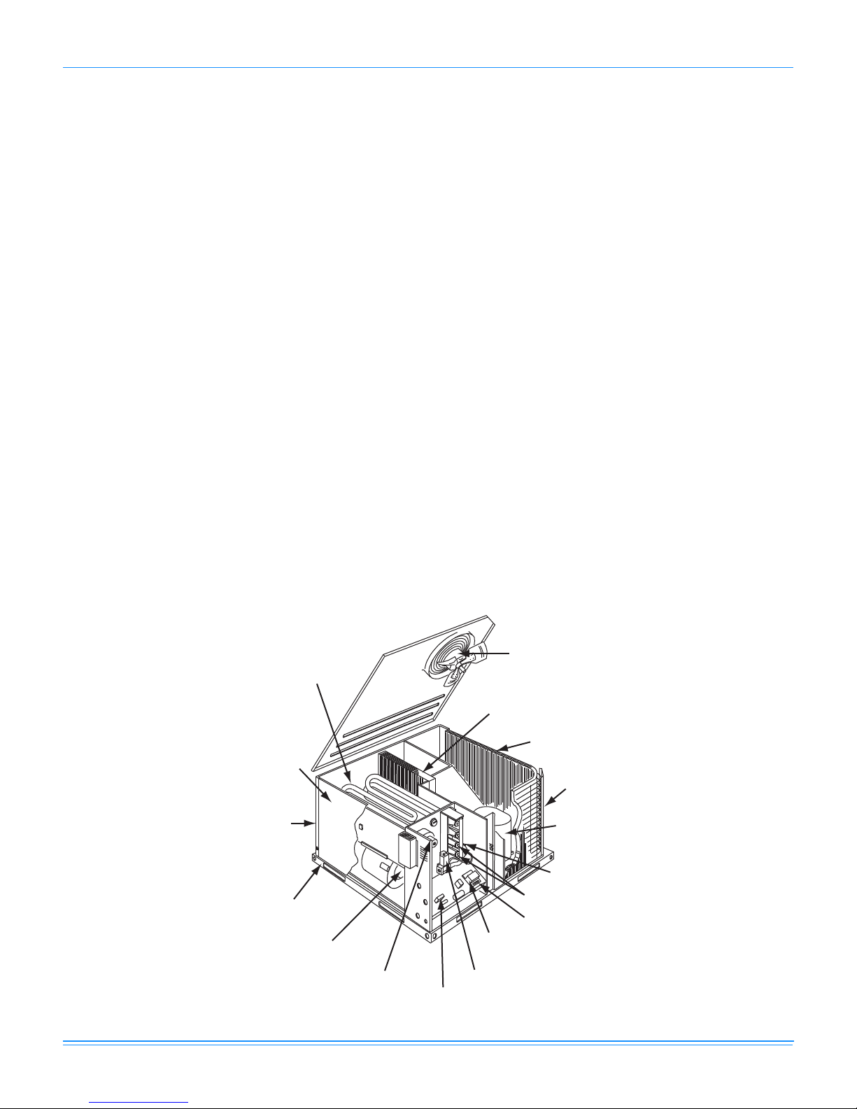
Component Location
Cooling/Gas Unit
2 Johnson Controls Unitary Products

Nomenclature
D A 036 045
N
YY -F
Product Category
D = Single Package Air Conditioner
Product Generation
A = 1st Generation
B = 2nd Generation
Factory Installed Gas Heat
N = Single Stage
D = Two Stage
Product Identifier
YY = R-410A 14 SEER
Gas Heat/Electric
Voltage Code
F = 208/230-1-60
T = 208/230-3-60
W = 460-3-60
024 = 24,000 BTUH
036 = 36,000 BTUH
048 = 48,000 BTUH
060 = 60,000 BTUH
Nominal Cooling Capacity (MBH)
Nominal Gas Heating Input Capacity
(Nominal Low Gas Heat Input Capacity)
045 = 45,000 BTUH
070 = 70,000 BTUH (45,500 BTUH)
080 = 80,000 BTUH
090 = 90,000 BTUH (58,500 BTUH)
110 = 110,000 BTUH (70,200 BTUH)
135 = 135,000 BTUH (87,750 BTUH)
Cooling/Gas Unit
659501-LTG-A-1010
Features and Benefits
Standard Features
• Operating Efficiency - All gas units provide a minimum
AFUE of 80% and 14 SEER efficiency. All efficiencies
exceed legislated minimum levels.
• On Site Flexibility - All model sizes share a common,
compact design cabinet in a single footprint. The installer
has the flexibility of setting one curb and placing the
proper tonnage unit on that curb after the internal load has
been determined. Field convertible duct connections from
side shot to down shot allows the installer to have greater
flexibility with less inventory.
• Lower Installation Cost - Installation time and costs are
reduced by easy power and control wiring connections.
The small base dimension means less space is required
on the ground or roof, plus, the installer can fit this unit
between the wheel wells of full size pick-up truck.
All units are completely wired, charged with R-410A and
tested prior to shipment. Unique test stations using a new
state of the art computerized process system are used to
insure product quality. Refrigerant charge and component
part numbers are verified via computers at assembly. Vital
run test statistics such as system pressure, motor
currents, air velocity and temperature, unit vibration, and
gas system safeties are monitored and recorded by the
system to insure unit performance.
Equal size, side supply and return duct connections
allows easy hook-up of ducts to match low crawl spaces
without transition pieces.
• Utility Connections Made Easy - Gas and electric utility
knockouts are provided through the bottom as well as the
side of the unit. Utility connections can be made quickly and
with a minimum amount of field labor. A field supplied and
field installed electrical disconnect switch must be installed.
• Convertible Airflow Design - The bottom duct openings
are covered when they leave the factory ready to be used
Johnson Controls Unitary Products 3
for a side supply/side return application. If a bottom
supply/bottom return application is desired, you simply
remove the two panels from the bottom of the unit and
place them in the side supply/side return duct openings.
No panel cutting is required and no accessory panel is
necessary. Convertible airflow design allows maximum
field flexibility and minimum inventory.
• Condensate Pan - A non-corrosive, long-lasting, watertight pan is positioned below the evaporator coil to collect
and drain all condensate. Less collection of stagnate
condensate will build-up. The condensate pan conforms
to ASHRAE 62-89 standards (Ventilation for Acceptable
Indoor Air Quality).
• Condensate Drain - The 3/4 inch NPTF connection is
rigidly mounted to assure proper fit and leak tight seal.
• Durable Finish - With a heavy duty cabinet made of
powder-painted, galvanized steel the neutral color blends
into surrounding areas. The powdered paint provides a
better paint to steel bond, which resists corrosion and rust
creep. The special primer formulas and glossy finish
insures less fading when exposed to sunlight and offers a
more attractive on site appearance. This paint finish
meets ASTM-B117 standards for 1000 hours salt spray
rating. The highest in the industry.
• Full Perimeter Base Rails - The easily removable base
rails provide a solid foundation for the entire unit and
protects the unit during shipment. The rails provide fork lift
access from all sides, and rigging holes are also provided
so that an overhead crane can be used to place the units
on a roof. On applications where the unit is placed on a
pad, the base will keep the unit off the pad to deter
corrosion. On applications where height is limited, the inch
high base rails may be removed on location.
• More Attractive Appearance - A single piece Water
Shed top cover containing a top discharge condenser fan
arrangement requires less square footage on installation
and provides a wider variety of installations. The one
piece design adds greater water integrity. Rounded

659501-LTG-A-1010
corners with water drip edges add to the attractive
appearance. The cabinet panels have a non-fibrous
insulation that will not release insulation fibers into
conditioned area.
• Top Discharge - The top discharge condenser fan does
not disrupt neighboring areas or dry-out vegetation
surrounding the unit. The warm air from the top mounted fan
is blown up away from the structure and any landscaping.
This allows compact location on multi-unit applications.
• Condenser Coil Grille - A multi-piece totally enclosed,
rigidly mounted condenser coil grille provides protection
from objects after installation and provides protection
during transit.
• Low Operating Sound Level - The upward air flow
carries the normal operating noise up and away from the
living area. The rigid top panel effectively isolates any
motor sound. Isolator mounted compressor and the
rippled fins of the condenser coil muffle the normal fan
motor and compressor operating sounds. The unique
formed base pan also aids in sound alterations with it's
Super-Structure design. This design strategically places
embossments in the pan for optimum strength and rigidity.
• Fan System - All models operate over a wide range of
design conditions with an electrically commutated fan
motor. These units easily match all types of applications
and provide greater on site flexibility to match comfort
requirement. The cooling speed is factory set and can be
field adjusted to a second speed. The heating speed is
factory set to maintain mid point rise at the units heating
input, but can be field adjusted. This allows maximum
comfort conditions.
• Simple Control Circuit - A low voltage printed circuit
board contains a diagnostic indicator light and a low
voltage terminal strip. An additional set of pin connectors
is also provided to simplify the field interface of external
controls. Mate-n-lock plug connectors are used. The
electrical control box is not located in the compressor
compartment. The controls are mounted on a Control-Tilt
control panel to allow the access cover to be removed for
trouble shooting and maintenance without affecting the
normal system operating pressures. All wiring internal to
the unit is color/number coded.
• Protected Compressor - The compressor is internally
protected against high pressure and temperature. This is
accomplished by the simultaneous operation of high
pressure relief valve and a temperature sensor which protect
the compressor if undesirable operating conditions occur.
• Pressure Switches - High pressure and low pressure/
loss of charge switches standard in all units. When
abnormal conditions are sensed through the pressure
switches, the unit will lock out preventing any further
operation until reset or problem is corrected.
• Exclusive Coil Design - Grooved copper tubes and
enhanced aluminum fin construction improves heat
transfer for maximum efficiency and durability.
• Heat Exchangers - Are corrosion-resistant, aluminizedsteel tubular construction to provide long-life, trouble-free
operation. The unique blow-through design also assures
that condensate does not collect in humid areas when in
the cooling cycle. This adds to longer heat exchanger life
and higher long term efficiencies.
• Post Purge Induced Draft Combustion - Exhausts
combustion products from the heat exchanger upon
completion of the heating cycle to prolong the heat
exchanger life.
• Self Diagnostic Fan Control Module - Due to this self
diagnostic control, less on site time is required to trouble
shoot these units.
• Spark To Pilot Ignition - Provides faster heat delivery.
This ignition is highly reliable, durable and eliminates
nuisance lockouts.
• Multi Port In-shot Burners - No field adjustment is
required to mix the air and gas. These burners are
constructed of high-grade corrosion-resistant, aluminizedsteel.
• Low Maintenance - Long life, permanently lubricated
condenser and evaporator fan motor bearings need no
annual maintenance adding greater reliability to the unit.
Blower assembly can be easily cleaned by the unique
Slip- Track slide-out blower assembly.
• Secured Service Access Ports - Protected, externally
mounted, re-usable service access ports are provided on
both the high and low lines for ease of evacuating and
charging the system. No final field mounting required.
• Easy Service Access - A large, single panel covers the
electrical and gas controls makes servicing easy. The
blower compartment has an additional large panel with a
built-in handle tab. Removing this panel will allow the
blower assembly to slide-out for easy removal for
maintenance and ease of trouble shooting.
• Replacement Parts - The installer requires no special
training to replace any of the components of these units
and does not need to maintain an inventory of unique parts.
• System Integration - Each unit has the internal ability to
integrate an electronic air cleaner or humidifier to work in
conjunction with the base unit.
Field Installed Accessories
• Low NOx Kit - Kit includes all the necessary hardware
and instructions to field convert units to reduce emissions
to less than 40 nanogram per Joule. California
requirement on single phase models only.
• Propane Conversion Kit - Kit includes burner orifices,
gas valve conversion and installation instructions
necessary to field convert unit from natural gas to propane.
• High Altitude Conversion Kit (Natural Gas/Propane) - Kit
includes all necessary labels and instructions to field alte r
units with natural gas/propane for installations above 2000
feet. Burner orifices must be obtained from Source 1 Parts.
Propane Conversion Kit must be obtained separately.
• Economizer Down Discharge/Supply Kit - Modulating
integrated economizer provides simultaneous operation
4 Johnson Controls Unitary Products

659501-LTG-A-1010
between the mechanical cooling and economizer
operation. Independent blade design insures proper
control and less than 1% leak rate. Includes hood and
mesh bird screen filter integrated into the hood, dry bulb
sensor and relief damper. Separate field accessories of
single enthalpy and dual enthalpy are also available. A
built-in barometric relief of 25% is provided.
• Single Enthalpy Sensor - Sensor replaces dry bulb
sensor standard in economizer kit. Provides improved
economizer operation by sensing the dry bulb
temperature from outdoors plus the enthalpy content of
the outdoor air.
• Dual Enthalpy Sensor - Additional sensor to single
enthalpy sensor. Sensor senses both the return air
temperature dry bulb and humidity in conjunction with the
single enthalpy to determine the most economical mix.
Single Enthalpy sensor also required.
• Hail Guard Kit - Kit contains protective grilles made of
expanded aluminum with full perimeter frame. Sloped
hoods are also included to assure maximum protection.
• Filter/Frame Kit (Single Phase Only) - Kit contains the
necessary hardware to field install return air filters into the
base unit. Pre-cut filter racks and appropriate cleanable
standard size filters are shipped in one kit. The filter rack
is suitable for either 1" or 2" filters. (1" filter is supplied)
This kit is available for single phase horizontal or vertical
duct application only. Standard in all 3 Phase models.
• Motorized Fresh Air Damper - Designed for duct
mounted side supply/return and unit mounted down
supply/return applications. Damper capable of providing
0% through 50% of outdoor air (field supplied). Closes on
power loss, includes hood and screen assembly.
• Rectangle To Round Adapters - Kit includes one supply
and one return air rectangle to round duct adapter.
Adapters are preformed and designed to fit over current
duct openings on the base unit. Transition is from side
square duct opening to 14" round duct opening.
• Roof Curbs - NRCA approved curbs provide proper fit to
base unit for rooftop installations. Curbs are designed to
be assembled through hinge pins in each corner. Kit also
provides seal strip to assure a water tight seal. 8 and 14
inch high roof curbs are available.
• Manual Outdoor Damper - Provides 0% through 50%
outdoor air capability (field adjustable). Designed for duct
mounted side supply/return applications. Includes hood
and screen assembly.
• Wall Thermostat - The units are designed to operate with
24-volt electronic and electro-mechanical thermostats. All
units can operate with single stage heat/single stage cool
thermostats - with or without the economizer.
• Low Ambient Kit - Kit provides necessary hardware to
convert unit to operate in cooling cycle down to 0º F.
Standard unit operation 45º F.
• Transformer Kit - Kit provides necessary hardware to
provide single phase models from factory furnished 40 VA
transformer capability to 75 VA transformer capability.
(Required on installations with economizer or motorized
damper.)
Guide Specifications
General
Units shall be manufactured by Unitary Products in an ISO
9001 certified facility. Luxaire Acclimate™ package units give
you the flexibility and choices you need in today’s market.
These packaged cooling/heating air conditioners are designed
for outdoor installation. Only utility and duct connections are
required at the point of installation. The single or two stage gas
fired heaters have aluminized steel tubular heat exchangers
and spark to pilot ignition. They are available in natural gas with
field conversion to propane.
Description
Units shall be factory-assembled, single packaged, Electric
Cooling/Gas Heating units, designed for outdoor mounted
installation. For SEER ratings, refer to technical literature. They
shall have built in, equal size, field convertible duct connections
for down discharge supply/return or horizontal discharge
supply/return. The units shall be factory wired, piped, charged
with R-410A Refrigerant and factory tested prior to shipment. All
unit wiring shall be both numbered and color coded. All units
shall be manufactured in a facility certified to ISO 9001
standards, and the cooling performance shall be rated in
accordance with DOE and ARI test procedures. The heating
performance shall be rated to DOE and GAMA test procedures.
Units shall be CSA listed and classified to ANSI Z21.47/CAN/
CSA 2.3 standards and UL 1995/CAN/CSA No. 236-M90
conditions.
Unit Cabinet
Unit cabinet shall be constructed of galvanized steel, with
exterior surfaces coated with a non-chalking, powdered paint
finish, certified at 1000 hours salt spray test per ASTM-B117
standards. The unit top shall be a single piece “Water Shed”
design, with drip edges and no-seam corners to provide
optimum water integrity. Unit shall have a rigidly mounted
condenser coil guard to provide protection from objects and
personnel after installation. Indoor blower section shall be
insulated with up to 3/4” thick, aluminum, foil faced insulation,
fastened to prevent insulation from entering the air stream.
Cabinet panels shall be “large” size, easily removable for
servicing and maintenance, with built-in lift handles. Unit shall
be built on a formed, “Super-Structure” design base pan, with
embossments at critical points to add strength, rigidity and aid
in minimizing sound. Full perimeter base rails shall be provided
to assure reliable transit of equipment, overhead rigging, for
truck access and proper sealing on roof curb applications. Base
rails shall be removable, when required, to lower unit height.
Filters shall be furnished and be accessible through a
removable access door, sealed airtight. Units vertical discharge
and return duct configuration shall be designed to fit between
standard 24” O.C. beams without modification to building
structure, duct work and base unit. Condensate pan shall be
Johnson Controls Unitary Products 5

659501-LTG-A-1010
internally sloped and conform to ASHRAE 62-89 self-draining
standards, with 3/4” NPTF ridged mount connection.
Indoor (Evaporator) Fan Assembly
Fan shall be direct drive design. Fan wheel shall be double-inlet
type with forward-curved blades, dynamically balanced to
operate smoothly throughout the entire range of opera tion.
Airflow design shall be constant air volume. Bearings shall be
sealed and permanently lubricated for longer life and no
maintenance. Fan assembly shall be “Slip Track” (slide-out)
design for easy removal and cleaning.
Outdoor (Condenser) Fan Assembly
The outdoor fan shall be of the direct-driven propeller type,
discharge air vertically, have aluminum blades riveted to
corrosion resistant steel spider bracket and shall be statically
balanced for smooth operation. The outdoor fan motor shall be
totally enclosed with permanently lubricated bearings and
internally protected against overload conditions.
Refrigerant Components
Compressors:
a. Shall be fully hermetic type, direct drive, internally
protected with internal high-pressure relief and over
temperature protection. The hermetic motor shall be
suction gas cooled and have a voltage range of +/- 10%
of the unit nameplate voltage.
b. Shall have internal isolation and sound muffling to
minimize vibration and noise, and be externally isolated
on a dedicated, independent mounting.
Coils:
a. Evaporator and condenser coils shall have aluminum
plate fins mechanically bonded to seamless internally
enhanced copper tubes with all joints brazed.
b. Evaporator coil shall be of the direct expansion, blow
through design, while condenser coil shall be draw
through design.
Refrigerant Circuit and Refrigerant Safety Components shall
include:
a. Shall include independent fixed orifice expansion
devices.
b. Shall include filter/strainer to eliminate any foreign
matter.
Gas Heating Section (If Equipped)
Heat exchanger and exhaust system shall be constructed of
aluminized steel and shall be designed with induced draft
combustion with post purge logic and redundant main gas
valve. The heat exchanger shall be of the tubular type,
constructed of T1-40 aluminized steel for corrosion resistance
and allowing minimum mixed air entering temperature of 40 ºF.
Burners shall be of the in-shot type, constructed of aluminumcoated steel. All gas piping shall enter the unit cabinet at a
single location through either the side or bottom, without any
field modifications. An integrated control board shall provide
timed control of evaporator fan functioning and burner ignition.
Heating section shall be provided with the following minimum
protection:
a. Primary and auxiliary high-temperature limit switches.
b. Induced draft pressure sensor.
c. Flame roll out switch (manual reset).
d. Flame proving controls.
6 Johnson Controls Unitary Products
659501-LTG-A-1010
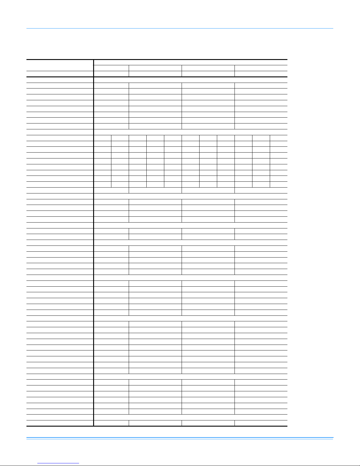
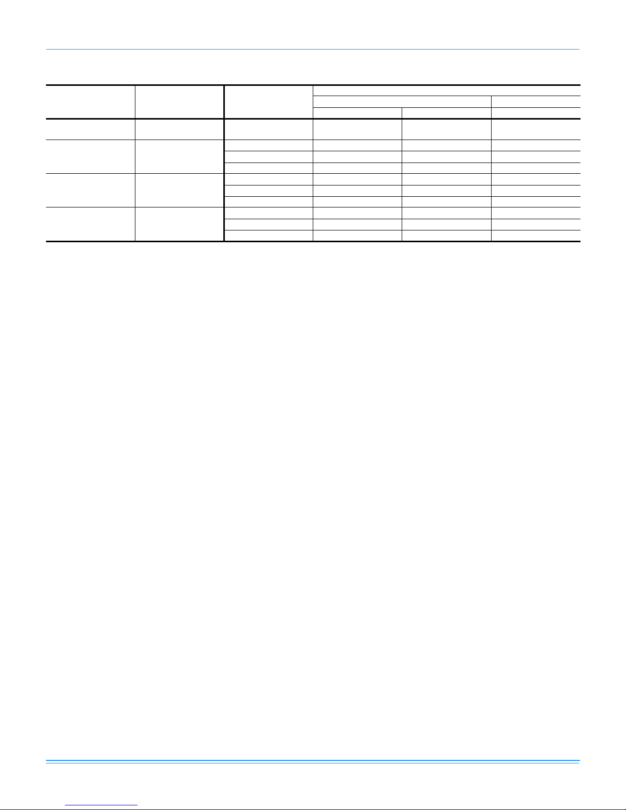
Physical Data
DYY024-060 Single Stage Gas Heat
Component
Nominal Tonnage 2.0 3.0 4.0 5.0
ARI COOLING PERFORMANCE
Gross Capacity @ ARI A point (Btu) 24.3 35.6 50.0 59.6
ARI net capacity (Btu) 23.8 34.6 48.0 56.5
EER 11.1 11.0 11.0 10.6
SEER 14.0 14.0 14.0 13.7
Nominal CFM 800 1200 1550 1650
System power (KW) 2.1 3.1 4.4 5.4
Refrigerant type R-410A R-410A R-410A R-410A
Refrigerant charge (lb-oz) 5-0 7-8 9-8 10-0
ARI HEATING PERFORMANCE
Heating model 45 70 45 70 90 80 110 135 80 110 135
Heat input (K Btu) 45 70 45 70 90 80 108 135 80 108 135
Heat output (K Btu) 36 56 36 56 72 64 87 108 64 87 108
AFUE % 80.0 80.0 80.0 80.0 80.0 80.0 80.0 80.0 80.0 80.0 80.0
Steady state efficiency (%) 8080808080808080808080
No. burners 23234345345
No. stages 11111111111
Temperature Rise Range (ºF) 25-55 30-60 25-55 25-55 30-60 25-55 35-65 45-75 25-55 35-65 45-75
Gas Limit Setting (ºF) 140 160 140 160 160 150 175 160 150 175 160
Gas piping connection (in.) 1/2 1/2 1/2 1/2
DIMENSIONS (inches)
Length 49 1/8 49 1/8 49 1/8 49 1/8
Width 47 1/4 47 1/4 47 1/4 47 1/ 4
Height 33 1/2 33 1/2 41 1/2 41 1/2
OPERATING WT. (lbs.) 400 440 500 540
COMPRESSORS
Type Scroll 2-spd Scroll 2-spd Scroll 2-spd Scroll 2-spd
Quantity 1 1 1 1
CONDENSER COIL DATA
Face area (Sq. Ft.) 11.7 11.7 14.7 14.7
Rows 1222
Fins per inch 20 16 20 20
Tube diameter (in.) 3/8 3/8 3/8 3/8
Circuitry Type Interlaced Interlaced Interlaced Interlaced
EVAPORATOR COIL DATA
Face area (Sq. Ft.) 3.4 3.4 4.4 4.4
Rows 2333
Fins per inch 15 13 16 16
Tube diameter 3/8 3/8 3/8 3/8
Circuitry Type Interlaced Interlaced Interlaced Interlaced
Refrigerant control TXV TXV TXV TXV
CONDENSER FAN DATA
Quantity 1 1 1 1
Fan diameter (Inch) 22 22 22 22
Type Prop Prop Prop Prop
Drive type Direct Direct Direct Direct
No. speeds 1 1 1 2
Number of motors 1 1 1 1
Motor HP each 1/4 1/4 1/3 1/3
RPM 1100 1100 1100 850/1100
Nominal total CFM 2400 2400 3000 3000
DIRECT DRIVE EVAP FAN DATA
Quantity 1 1 1 1
Fan Size (Inch) 10 x 8 11 x 10 11 x 10 11 x 10
Type Centrifugal Centrifugal Centrifugal Centrifugal
Motor HP each 1/2 3/4 1 1
RPM Variable Variable Variable Variable
Frame size 48 48 48 48
FILTERS
Quantity - Size 1 - 20 x 20 x 1 1 - 20 x 20 x 1 2 - 20 x 12 x 1 2 - 20 x 12 x 1
DYY024 DYY036 DYY048 DYY060
Models
Johnson Controls Unitary Products 7
659501-LTG-A-1010
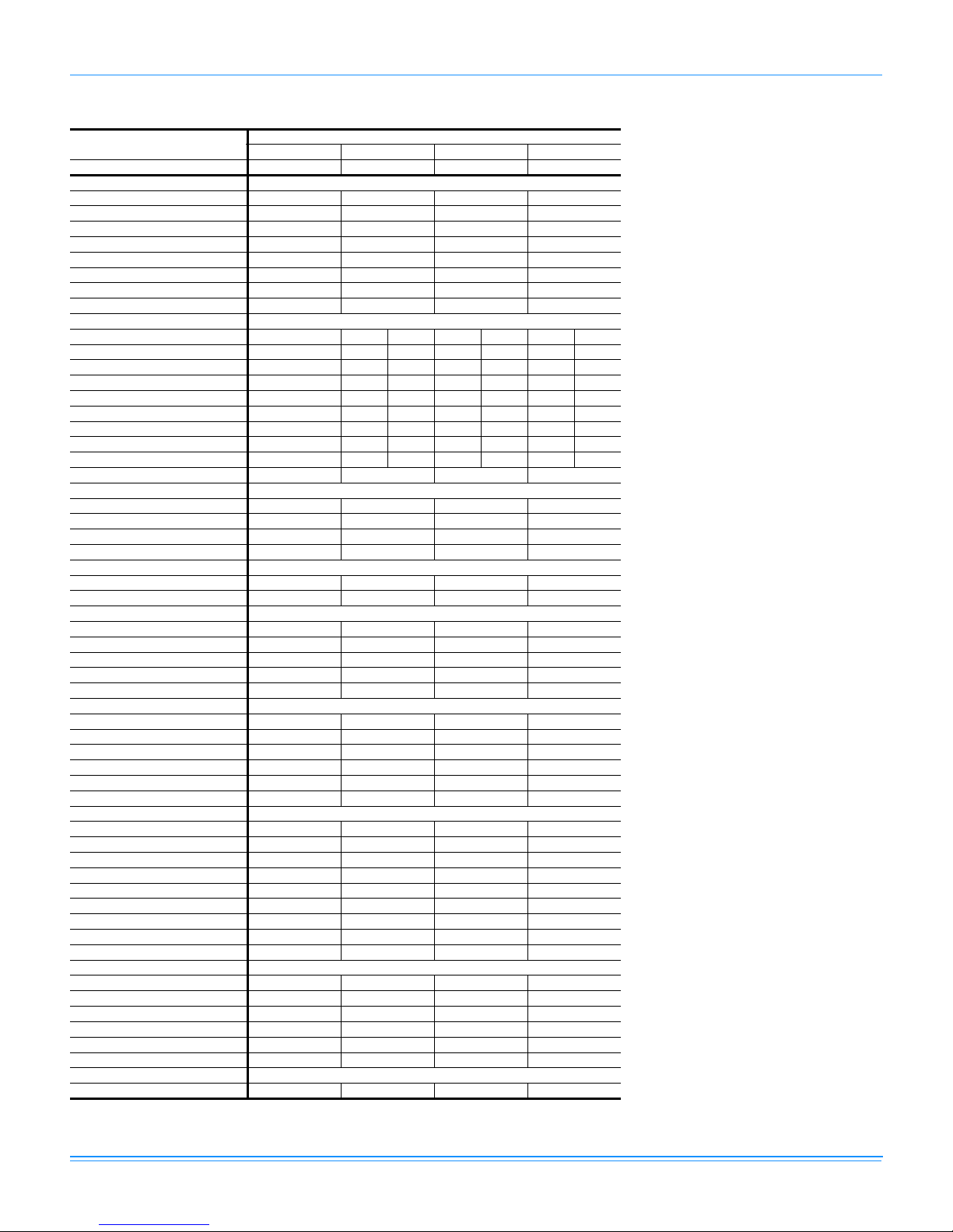
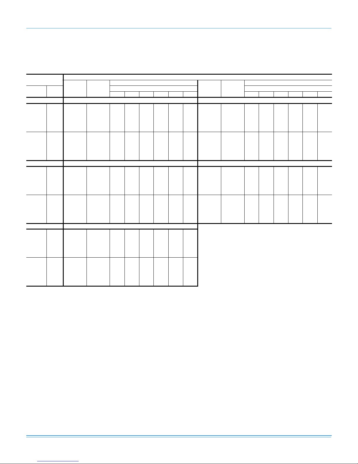
DYY024-060 Two Stage Gas Heat
Component
Nominal Tonnage 2.0 3.0 4.0 5.0
ARI COOLING PERFORMANCE
Gross Capacity @ ARI A point (Btu) 24.3 35.6 50.0 59.6
ARI net capacity (Btu) 23.8 34.6 48.0 56.5
EER 11.1 11.0 11.0 10.6
SEER 14.0 14.0 14.0 13.7
Nominal CFM 800 1200 1550 1650
System power (KW) 2.1 3.1 4.4 5. 4
Refrigerant type R-410A R-410A R-410A R-410A
Refrigerant charge (lb-oz) 5-0 7-8 9-8 10-0
ARI HEATING PERFORMANCE
Heating model 70 70 90 110 135 110 135
Heat input (K Btu) 70/45.5 70/45.5 90/58.5 108/70.2 135/87.8 108/70.2 135/87.8
Heat output (K Btu) 56/36.4 56/36.4 72/46.8 87/56.2 108/70.2 87/56.2 108/70.2
AFUE % 80.0 80.0 80.0 80.0 80.0 80.0 80.0
Steady state efficiency (%) 80 80 80 80 80 80 80
No. burners 3 344545
No. stages 2 222222
Temperature Rise Range (ºF) 30-60 25-55 30-60 35-65 45-75 35-65 45-75
Gas Limit Setting (ºF) 160 160 150 170 160 170 160
Gas piping connection (in.) 1/2 1/2 1/2 1/2
DIMENSIONS (inches)
Length 49 1/8 49 1/8 49 1/8 49 1/8
Width 47 1/4 47 1/4 47 1/4 47 1/4
Height 33 1/2 33 1/2 41 1/2 41 1/2
OPERATING WT. (lbs.) 400 440 500 540
COMPRESSORS
Type Scroll 2-spd Scroll 2-spd Scroll 2-spd Scroll 2-spd
Quantity 1111
CONDENSER COIL DATA
Face area (Sq. Ft.) 11.7 11.7 14.7 14.7
Rows 1222
Fins per inch 20 16 20 20
Tube diameter (in.) 3/8 3/8 3/8 3/8
Circuitry Type Interlaced Interlaced Interlaced Interlaced
EVAPORATOR COIL DATA
Face area (Sq. Ft.) 3.4 3.4 4.4 4.4
Rows 2333
Fins per inch 15 13 16 16
Tube diameter 3/8 3/8 3/8 3/8
Circuitry Type Interlaced Interlaced Interlaced Interlaced
Refrigerant control TXV TXV TXV TXV
CONDENSER FAN DATA
Quantity 1111
Fan diameter (Inch) 22 22 22 22
Type Prop Prop Prop Prop
Drive type Direct Direct Direct Direct
No. speeds 1112
Number of motors 1111
Motor HP each 1/4 1/4 1/3 1/3
RPM 1100 1100 1100 850/1100
Nominal total CFM 2400 2400 3000 3000
DIRECT DRIVE EVAP FAN DATA
Quantity 1111
Fan Size (Inch) 10 x 8 11 x 10 11 x 10 11 x 10
Type Centrifugal Centrifugal Centrifugal Centrifugal
Motor HP each 1/2 3/4 1 1
RPM Variable Variable Variable Variable
Frame size 48 48 48 48
FILTERS
Quantity - Size 1 - 20 x 20 x 1 1 - 20 x 20 x 1 2 - 20 x 12 x 1 2 - 20 x 12 x 1
DYY024 DYY036 DYY048 DYY060
Models
8 Johnson Controls Unitary Products
DYY Unit Limitations
Size
(Tons)
024
(2.0)
036
(3.0)
048
(4.0)
060
(5.0)
659501-LTG-A-1010
Unit Limitations
Model Unit Voltage
DYY 208/230-1-60 187 252 115
208/230-1-60 187 252 115
DYY
DYY
DYY
208/230-3-60 187 252 115
460-3-60 432 504 115
208/230-1-60 187 252 115
208/230-3-60 187 252 115
460-3-60 432 504 115
208/230-1-60 187 252 115
208/230-3-60 187 252 115
460-3-60 432 504 115
Applied Voltage Outdoor DB Temp
Min Max Max (°F)
Johnson Controls Unitary Products 9
659501-LTG-A-1010
Capacity Performance
DYY024-060 Cooling Capacities
DYY024 (2.0 Ton)
Air on
Evaporator Coil
CFM
600
800
600
800
600
800
WB
(°F)
77 24.5 1.2 11.3 8.5 8.8 - - - 23.2 1.4 11.9 9.9 8.2 - - 72 22.4 1.2 15.8 12.8 11.6 9.5 - - 21.0 1.4 15.4 13.2 11.0 8.8 - 67 20.4 1.2 20.4 17.0 14.4 11.8 9.2 - 18.8 1.4 18.8 16.4 13.8 11.1 8.5 62 18.0 1.2 18.0 18.0 17.4 13.4 9.4 5.5 16.9 1.3 16.9 16.9 16.6 12.5 8.4 4.4
57 19.2 1.0 19.2 19.2 19.0 14.8 10.5 6.3 17.5 1.3 17.5 17.5 17.3 13.2 9.0 4.8
77 31.7 1.9 14.9 13.2 10.7 - - - 30.3 2.1 15.5 12.8 10.2 - - 72 29.5 1.8 20.9 18.0 15.1 12.2 - - 27.9 2.0 20.4 17.4 14.5 11.5 - 67 27.2 1.8 26.9 22.8 19.5 16.3 13.0 - 25.5 2.0 25.3 22.0 18.8 15.5 12.2 62 24.8 1.7 24.8 24.8 23.9 20.5 17.2 13.8 23.4 1.9 23.4 23.4 22.9 19.5 16.0 12.5
57 25.3 1.8 25.3 25.3 25.3 21.7 17.9 14.1 23.6 2.0 23.6 23.6 23.5 19.9 16.3 12.7
77 21.8 1.6 12.4 11.3 7.5 - - - 19.8 1.8 12.9 8.6 6.7 - - 72 19.6 1.6 14.9 13.5 10.3 8.0 - - 17.7 1.8 14.3 11.2 9.6 7.2 - 67 17.3 1.5 17.3 15.8 13.1 10.4 7.8 - 15.6 1.7 15.6 13.8 12.5 8.9 5.3 62 15.8 1.5 15.8 15.8 15.8 11.6 7.4 3.3 14.3 1.7 14.3 14.3 14.3 10.0 5.1 1.5
57 15.8 1.5 15.8 15.8 15.7 11.5 7.4 3.3 14.6 1.7 14.6 14.4 14.3 10.9 7.5 4.1
77 28.9 2.2 16.0 12.4 9.6 - - - 26.6 2.5 16.9 11.9 8.9 - - 72 26.3 2.2 19.9 16.9 13.8 10.8 - - 24.1 2.4 19.3 16.2 13.0 9.9 - 67 23.8 2.2 23.8 21.3 18.0 14.6 11.3 - 21.7 2.4 21.7 20.5 17.1 13.7 10.3 62 21.9 2.1 21.9 21.9 21.9 18.4 14.8 11.3 20.1 2.4 20.1 20.1 20.1 16.5 12.8 9.2
57 22.0 2.1 22.0 22.0 21.5 18.1 14.7 11.3 20.5 2.4 20.5 20.5 19.9 16.4 12.9 9.4
77 17.7 2.0 13.4 5.9 5.9 - - 72 15.8 1.9 13.7 8.9 8.9 6.5 - 67 14.0 1.9 14.0 11.9 11.9 7.4 2.9 62 12.9 1.9 12.9 12.9 12.9 8.5 2.8 -0.3
57 13.5 1.9 13.5 13.0 13.0 10.3 7.5 4.8
77 24.2 2.7 17.8 11.3 8.2 - - 72 21.9 2.7 18.7 15.5 12.2 9.0 - 67 19.6 2.7 19.6 19.6 16.3 12.8 9.3 62 18.3 2.6 18.3 18.3 18.3 14.6 10.8 7.1
57 19.1 2.7 19.1 19.1 18.3 14.7 11.1 7.4
Net
Capacity
(MBh)
Total
1
Input
2
(kW)
Sensible Capacity (MBh)
Return Dry Bulb (°F) Return Dry Bulb (°F)
90 85 80 75 70 65 90 85 80 75 70 65
75°F 85°F
95°F 105°F
115°F
1. These capacities are Net Capacities.
2. These ratings include the compressor, condenser fan and supply air blower motors.
Temperature of Air on Condenser Coil
Net
Capacity
(MBh)
Total
1
Input
2
(kW)
Sensible Capacity (MBh)
10 Johnson Controls Unitary Products
DYY036 (3.0 Ton)
Air on
Evaporator Coil
CFM
825
1200
825
1200
825
1200
WB
(°F)
77 33.3 1.6 17.1 12.2 12.0 - - - 31.5 1.8 16.9 13.9 11.0 - - 72 30.9 1.6 22.7 18.0 16.2 12.9 - - 28.9 1.8 21.5 18.4 15.2 12.0 - 67 28.5 1.6 28.3 23.9 20.4 16.9 13.5 - 26.3 1.8 26.1 22.8 19.4 16.0 12.7 62 26.0 1.6 26.0 26.0 25.0 20.9 16.9 12.9 23.8 1.9 23.8 23.8 23.2 19.4 15.6 11.7
57 22.7 1.6 22.7 22.7 22.7 18.9 15.1 11.3 22.5 1.8 22.5 22.5 22.5 18.7 14.9 11.0
77 45.8 3.0 21.0 18.6 15.2 - - - 43.1 3.1 20.6 17.2 13.7 - - 72 41.9 2.7 28.7 24.8 20.9 17.0 - - 39.6 3.0 28.0 24.1 20.2 16.2 - 67 38.0 2.4 36.4 31.0 26.7 22.4 18.0 - 36.2 2.8 35.4 31.0 26.6 22.2 17.8 62 35.4 2.5 35.4 35.4 34.2 29.5 24.7 20.0 33.3 2.8 33.3 33.3 32.5 27.7 23.0 18.2
57 35.2 2.5 35.2 35.2 35.2 30.3 25.3 20.4 33.6 2.8 33.6 33.6 33.6 28.6 23.7 18.7
77 29.7 2.1 16.7 15.7 10.0 - - - 26.6 2.3 17.4 12.8 10.0 - - 72 26.9 2.1 20.3 18.7 14.2 11.1 - - 24.2 2.4 19.6 15.8 13.6 10.6 - 67 24.0 2.1 24.0 21.7 18.4 15.1 11.9 - 21.7 2.4 21.7 18.8 17.2 13.9 10.6 62 21.6 2.1 21.6 21.6 21.5 17.9 14.2 10.6 20.0 2.4 20.0 20.0 20.0 16.3 11.3 9.1
57 22.3 2.1 22.3 22.3 22.3 18.5 14.6 10.8 20.7 2.3 20.7 20.7 20.7 17.1 13.4 9.8
77 40.4 3.3 20.3 15.8 12.3 - - - 37.9 3.7 21.1 15.3 11.8 - - 72 37.4 3.3 27.3 23.4 19.4 15.4 - - 34.7 3.6 26.3 22.4 18.4 14.5 - 67 34.3 3.3 34.3 30.9 26.5 22.0 17.5 - 31.6 3.6 31.6 29.5 25.0 20.5 16.0 62 31.2 3.1 31.2 31.2 30.8 26.0 21.2 16.4 28.8 3.4 28.8 28.8 28.6 23.8 19.0 14.3
57 32.0 3.1 32.0 32.0 32.0 27.0 22.1 17.1 29.8 3.4 29.8 29.8 29.8 24.9 19.9 15.0
77 23.6 2.6 18.1 9.9 9.9 - - 72 21.5 2.6 18.8 13.0 13.0 10.1 - 67 19.4 2.6 19.4 16.0 16.0 12.7 9.3 62 18.4 2.6 18.4 18.4 18.4 14.8 8.3 7.6
57 19.2 2.6 19.2 19.2 19.2 15.7 12.2 8.7
77 35.3 4.2 21.9 14.8 11.4 - - 72 32.1 4.0 25.4 21.4 17.5 13.5 - 67 28.8 3.8 28.8 28.1 23.6 19.1 14.5 62 26.4 3.8 26.4 26.4 26.4 21.6 16.9 12.1
57 27.6 3.8 27.6 27.6 27.6 22.7 17.8 12.8
Net
Capacity
(MBh)
Total
1
Input
2
(kW)
Sensible Capacity (MBh)
Return Dry Bulb (°F) Return Dry Bulb (°F)
90 85 80 75 70 65 90 85 80 75 70 65
75°F 85°F
95°F 105°F
115°F
1. These capacities are Net Capacities.
2. These ratings include the compressor, condenser fan and supply air blower motors.
Temperature of Air on Condenser Coil
Net
Capacity
(MBh)
659501-LTG-A-1010
Total
1
Input
2
(kW)
Sensible Capacity (MBh)
Johnson Controls Unitary Products 11
659501-LTG-A-1010
DYY048 (4.0 Ton)
Air on
Evaporator Coil
CFM
1000
1550
1000
1550
1000
1550
WB
(°F)
77 45.3 2.3 23.5 17.6 15.0 - - - 42.2 2.5 22.9 18.4 14.0 - - 72 41.6 2.3 29.5 24.1 20.4 15.8 - - 38.8 2.5 28.5 23.9 19.3 14.6 - 67 37.9 2.3 35.5 30.6 25.7 20.9 16.0 - 35.4 2.5 34.1 29.3 24.5 19.7 14.8 62 36.2 2.1 36.2 36.2 30.6 26.1 21.6 17.2 32.4 2.5 32.4 32.4 29.5 25.0 20.4 15.9
57 33.3 2.3 33.3 33.3 31.8 27.4 22.9 18.4 31.4 2.5 31.4 31.4 30.4 25.9 21.3 16.8
77 66.5 3.7 31.4 27.2 21.4 - - - 61.9 4.0 32.0 26.0 20.1 - - 72 59.9 3.7 42.4 36.0 29.7 23.4 - - 56.3 4.0 41.3 34.9 28.5 22.1 - 67 53.3 3.6 53.3 44.9 38.0 31.1 24.3 - 50.7 3.9 50.7 43.9 37.0 30.1 23.2 62 49.4 3.5 49.4 49.4 47.4 40.1 32.8 25.6 47.1 3.7 47.1 47.1 45.6 38.4 31.2 24.0
57 52.2 3.4 52.2 52.2 48.1 41.2 34.2 27.2 49.3 3.7 49.3 49.3 45.9 38.8 31.7 24.6
77 39.1 2.8 22.3 19.3 13.1 - - - 36.6 3.1 23.8 15.4 12.3 - - 72 36.1 2.8 27.6 23.7 18.2 13.4 - - 33.3 3.1 26.9 20.1 17.3 12.6 - 67 33.0 2.8 32.8 28.0 23.2 18.4 13.7 - 30.0 3.1 30.0 24.7 22.3 17.6 12.9 62 28.5 3.0 28.5 28.5 28.5 23.9 19.3 14.7 25.9 3.3 25.9 25.9 25.9 21.1 16.2 11.5
57 29.6 2.8 29.6 29.6 29.0 24.4 19.8 15.1 27.0 3.1 27.0 27.0 26.7 21.8 16.9 11.9
77 57.3 4.3 32.7 24.7 18.7 - - - 54.5 4.7 33.9 23.6 17.5 - - 72 52.6 4.2 40.3 33.8 27.3 20.8 - - 49.4 4.6 39.1 32.6 26.0 19.4 - 67 48.0 4.2 48.0 43.0 36.0 29.0 22.1 - 44.4 4.5 44.4 41.5 34.5 27.4 20.3 62 44.8 4.0 44.8 44.8 43.8 36.7 29.6 22.4 41.7 4.3 41.7 41.7 41.1 33.9 26.7 19.5
57 46.3 4.0 46.3 46.3 43.6 36.4 29.2 22.1 43.4 4.3 43.4 43.4 40.9 33.7 26.5 19.3
77 34.1 3.4 25.3 11.6 11.6 - - 72 30.6 3.4 26.2 16.5 16.5 11.7 - 67 27.1 3.5 27.1 21.4 21.4 16.8 12.2 62 23.3 3.6 23.3 23.3 23.3 18.3 13.2 8.3
57 24.4 3.4 24.4 24.3 24.3 19.2 14.0 8.8
77 51.6 5.0 35.2 22.5 16.4 - - 72 46.2 4.9 38.0 31.3 24.7 18.0 - 67 40.7 4.9 40.7 40.1 32.9 25.7 18.6 62 38.5 4.7 38.5 38.5 38.5 31.2 23.9 16.6
57 40.5 4.7 40.5 40.5 38.3 31.1 23.8 16.6
Net
Capacity
(MBh)
Total
1
Input
2
(kW)
Sensible Capacity (MBh)
Return Dry Bulb (°F) Return Dry Bulb (°F)
90 85 80 75 70 65 90 85 80 75 70 65
75°F 85°F
95°F 105°F
115°F
1. These capacities are Net Capacities.
2. These ratings include the compressor, condenser fan and supply air blower motors.
Temperature of Air on Condenser Coil
Net
Capacity
(MBh)
Total
1
Input
2
(kW)
Sensible Capacity (MBh)
12 Johnson Controls Unitary Products
 Loading...