

INSTALLATION
INSTRUCTION
MODELS K*BU060A, K*BC090A, & K*BC120A
AIR COOLED
SPLIT-SYSTEM AIR CONDITIONERS
Supersedes: 550.23-N2W (589) 550.23-N2Z (399)
035-16673
GENERAL
These completely assembled 5, 7-1/2 and 10 ton blower
units include a well insulated cabinet, a DX cooling coil with
copper tubes and aluminum fins, an expansion valve, a
distributor, throwaway filters, a centrifugal blower, a blower
motor contactor and a small holding charge of refrigerant-22.
Blower motors and adjustable drives are factory-installed on
all units.
The units are shipped in the vertical position ready for field
installation . For horizontal installation, re ver se the sol id
bottom panel and the return air duct flange on the front of
the unit.
INSPECTION
As soon as a unit is received, it should be inspected for
possibl e damage during tr an sit. If damage is evid en t, the
Installer should pay particular attention to the words:
tion easier.
damage may resu lt if installation procedure is not handled properly.
Cautions are given to prevent equipment damage. Warnings are given to alert installer that personal injury and / or equipment
NOTE, CAUTION
extent of th e damage should be noted o n the carrier’s freight
bill. A separate request for inspection by carrier’s agent
should be made in writing.
RENEWAL PARTS
Refer to Parts Manual for complete listing of replacement
parts on this equipment for complete listing of replacement
parts. The forms referenced in this instruction may be
ordered from:
Publications Distribution Center
Unitary Products Group
P.O. Box 1592, York, PA. 17405
This instruction covers the installation and operation of
evaporator blower units. For information on the operation of
the matching condensing unit, refer to Forms 550.46-N1W,
550.46-N2W and 55 0. 23- N 1W.
WARNING.
and
Notes are intended to clarify or make the installa-
550.23-N2Z
TABLE OF CONTENT
TABLES
General................................................................................1
Renewal Parts............. .. .......................................................1
Inspection............ .. ...............................................................1
INSTALLA TION
Limitations............................................................................3
Location...... ..........................................................................3
Clearances...........................................................................3
Rigging and Handling .......................................................... 4
Vertical / Horizontal Installation............................................ 4
Duct Conn ections................................................................. 4
Refrigerant Mains.................................................................5
Drain Connection.................. .. .. ...........................................6
Supply Air Blower Adjustment.............................................6
Power and Control Wiring .................................................. 11
MAINTENANCE
Filters ................................................................................. 12
Evaporator Coil .................................................................. 12
Drain Pan ........................................................................... 12
Lubrication ......................................................................... 12
Belts ................................................................................... 12
No. Description Page
1 Unit Application Data.................................. 3
2 Physical Data.............................. .............. .. 5
3 Blower Motor Pulley Adjustment ................ 7
4 Blower Performance ................................... 8
5 Accessory Static Resistance...................... 8
6 Blower Motor and Drive Data..................... 8
7 Electrical Data ............................................ 11
FIGURES
No. Description Page
1 Unit Suspension Mounting......................... 3
2 Vertical & Horizontal Application................ 4
3 Supply Air Duct Connection....................... 4
4 Electric Heater Accessory .......................... 5
5 Supply Air Plenum Accessor .................... 5
6 Base Accessory...................... .............. ...... 5
7 Return Air Grille Accessory........................ 5
8 Recommended Drain Piping ...... ................ 6
9 Motor Mounting Assembly.......................... 7
10 Hole Locations for Pressure Readings....... 7
11 Pressure Drop vs. S u p pl y Air CFM ......... .. . 7
12 Unit Dimensions & Clearances (5 tons)..... 9
13 Unit Dimensions & Clearances ................. 10
(7-1/2 & 10Tons)
14 Typical Field W iring............ .. .. .... .. .. .. .. .. .. .... . 11
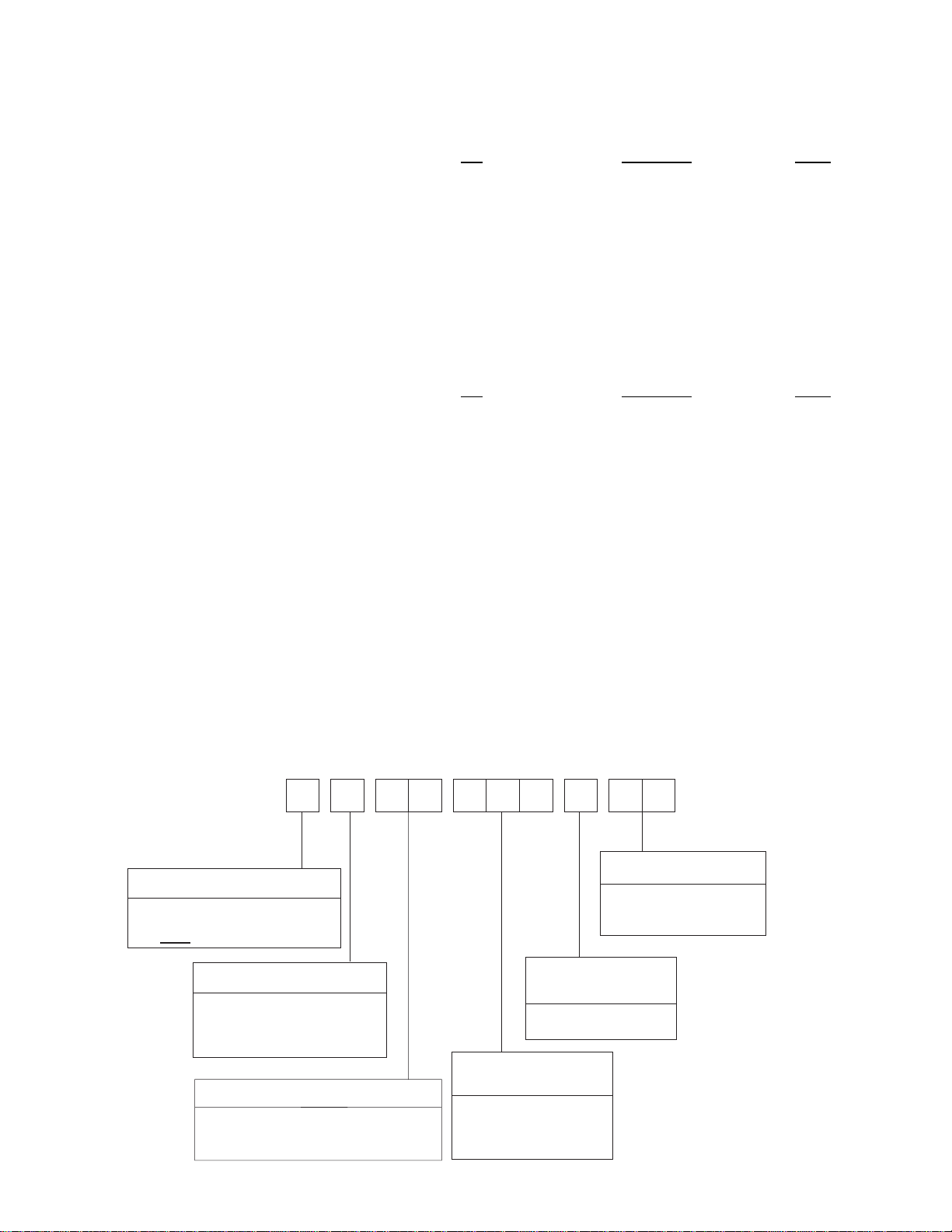
NOMENCLATUR
K B
B
U 090
PRODUCT CATEGORY
K- Split-System Evap. Blower
W ith M o to r a n d D riv e
PRODUCT GENERATION
B - 2nd G eneration
C - 3rd G eneration
D - 4th G eneration
NOM INAL
COOLING CAPACITY
PR O DUC T ID EN TIFIER
060 - 5 TO N
BU - E vap. B low er (5 Ton)
B C - E v a p . B lo w e r (7 -1 /2 & 1 0 T o n
2 Unitary Products Group
090 - 7-1/2 TO N
120 - 10 TO N
A
3 3
VOLTAGE CO D E
06 - 208/230-1-60
33 - 208/230/460-3-60
FAC TO R Y
INSTALLED HEAT
A - N ot A pplicable
INSTALLATION
550.23-N2Z
LIMITATIONS
This unit must be installed in accordance with all national
and local safety codes. If no local codes apply, installation
must conform to the appropriate national code. The unit is
designed to meet National Safety Code Standards. If
components are to be ad ded to a unit to meet local codes,
they are to be inst al led at the dea ler ’s and/or the customer’s
expense. See Table 1 for application limitations.
LOCATION
These Evaporator Blowers are not designed for outdoor
installation. They must be located within the building
structure, either inside or ou tside the conditioned space .
These Evaporator Blower sections allow for vertical or
horizontal installa t io n in any area offering proper electrical
The units should be located as c los e to th e con de ns i ng units
as practical and positioned to minimize bends in the
refrigerant piping.
Units being installed vertically or horizontally can be set
directly o n a floor or platform, or metal o r wooden beams
can support them.
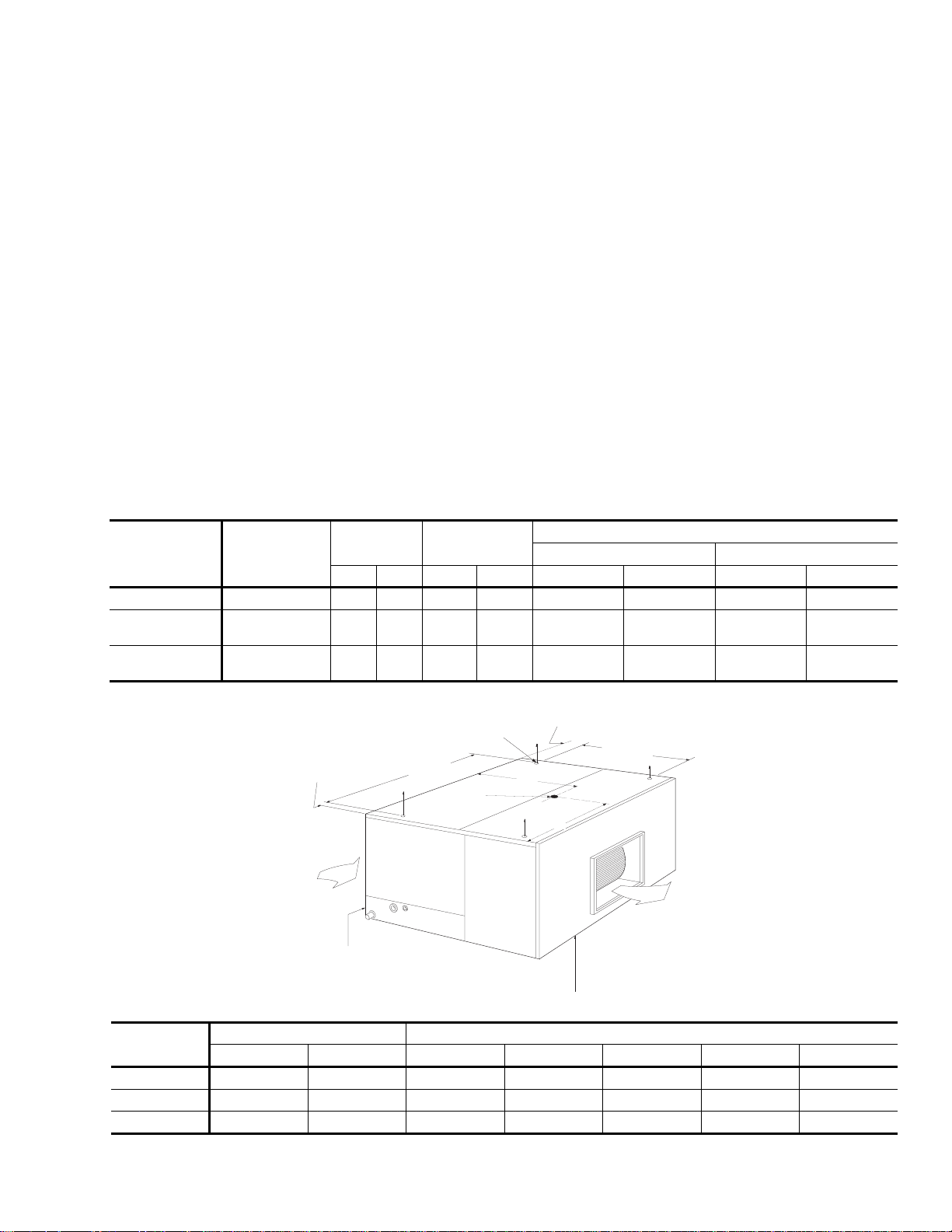
Units being installed hori z on ta lly can be suspended from
above. Four 3/8" weld nuts are provided in the unit frame to
accommodate hang er ro d s. Knockouts must be removed
from the unit panels to expose these weld nuts. Refer to
Figure 1 for t he ir location and the in di vi dual load on each
hanger rod.
WARNING: Be careful when attaching the hanger rods. They
must not be allowe d to turn or slip.
supply, duct and drai n connections.
CLEARANCES
They may be installed either with ductwork or matching
plenum and inlet grille.
TABLE 1
KBBU060A06 208/230-1-60 187 252 1600 2400 65/57 95/72 40 77
KBBC090A33
KBBC120A33
* Utilization Range "A" in accordance with ARI Standard 110
- UNIT APPLICATION DAT
Model
Power
Supply
208/230-3-60
460-3-60
208/230-3-60
460-3-60
Voltage
Variation
Supply Air
CFM
Min. Max. Min. Max. Min. Max. Min. Max.
187
252
432
187
432
2400 3600 65/57 95/72 40 77
504
252
3200 4800 65/57 95/72 40 77
504
Refer to the unit dimension details, Figures 12 and 13 for
clearances required for servicing and for proper unit
operation.
Entering Air Temperatures, °F
Cooling Coil - db/wb Heating Coil - db
2-5/8
W3
A
W2
B
SUPPLY AIR PLENUM AND
ELECTRIC HEATER ACCESSO RIES
IN S T A L L E D O N T H IS E N D O F T H E
UNIT.
37-9/16 (KEU060)
44-7/8 (KEU090, 120)
W4
AIR
OUT
Model
(4) 3/8"-16
W ELD NUUTS
34-1/2 (KEU060)
1-1/4 (KE U060)
1-3/8 (KE U090, 120)
AIR
IN
RETURN AIR GRILLE, HOT WATER
COIL AND STEAM COIL
ACCESSORIES INSTALLED ON
ON THIS END OF THE UNIT.
49-1/4 (KEU090, 120)
W1
CENTER
O F G R A V IT Y
Center of Gravity Dimensions (in.) Weight Distri bu tion (Lbs.)
A B W1 W2 W3 W4 TOTAL
KBU060 22-3/8 15-1/4 60 65 40 45 210
KBC090 26-1/4 23-3/4 85 93 70 77 325
KBC120 26-5/8 24-1/8 85 95 70 80 330
FIG. 1
- UNIT SUSPENSION MOUNTING (Horizontal Application)
Unitary Products Group 3
550.23-N2Z
RIGGING AND HANDLING
Be careful when moving the unit. Do not remove any
packaging until the unit is near its final location.
The packaging consists of a bottom wooden skid that can be
lifted with a fork truck from any direction, a corrugated
container that covers the entire unit, and strapping that
secures the container to the skid.
These units can be rigged with slings under the bottom skid
CAUTI ON: Spre ader bars should be used to pre vent the slings
from crushing the unit panels and frame.
Before rigging any unit, determine its weight from Table 2.
Before rigging a unit for horizontal installation, determine its
center of gravity from Figure 1, and make sure that its weight
will be distributed equally.
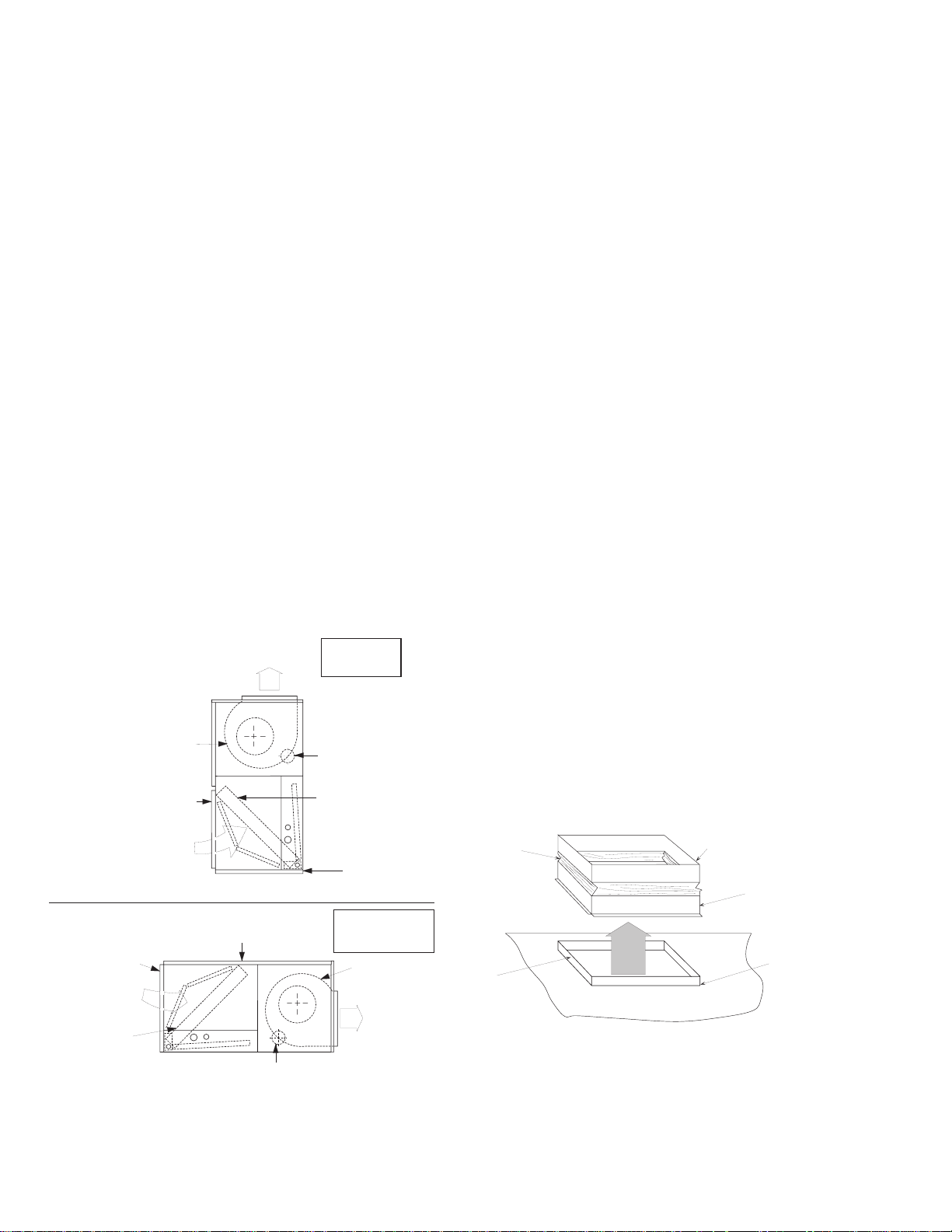
VERTICAL/HORIZONTAL INSTALL ATIO N
These evaporator blowers are shipped for vertical installation
with vertical air discharge as shown in Figure 2(A) but may
be conv erted for horiz on ta l insta ll at io n as sh own in Figure
2(B) by i nte rchanging the so l id bo ttom panel and the retu r
air duct flange.
DUCT CONNECTIONS
Design and install all ducts in accordance with all national
and/or local codes.
Refer to Figure 3 for suggested method of connecting supply
air ductwork.
Ducts should be sized no smaller than the duct fl a nges on
the unit or the electric heater (if used). Refer to the unit
dimension details (Fig ure 12 and 13) and th e heater detail
(Figure 4) for theses sizes. Refer to Form 550.12-N10.1U for
installation instructions on the electric heater.
Use flexible fiber glass or plastic cloth collars or other
non-flammable material at the unit duct connections to
minimize the transmission of noise and vibration.
Insulate all ductwork runn ing through un condi t ioned a reas to
prevent moisture condensation and to provide more
economical operation.
The return air duct flange is factory-mounted on the front of
the unit, but it can be reversed with the solid bottom panel for
horizontal applications. When the return air grille is us ed,
the duct connection frame is not used.
NOTE: If return air duct is not used, applicable installation
codes may limit the unit to installation only in a single
story residence.
A supply air plenum (Figure 5), a base (Figure 6), and a
return air grille (Figure 7) are available as field-installed
accessories, and one of the following respective instruction
forms will be packed with each.
• 550.13-N10.2U - Supply Air Plenum
• 550.13-N10.3U - Return Air Grille
• 550.12-N10.4U - Base
The supply air plenum and the return air grille should be
used in lieu of ductwork only when a free blow/free return
application is practical.
RETURN AIR
DUCT FLANGE
RETURN AIR
DUCT FLANGE
AIR
IN
COIL
BLOW ER
AIR
IN
AIR
OUT
(A )
SOLID
BOTTOM PAN EL
BLOW ER M OTOR
LO C A TIO N
(B )
VERTICAL
POSITION
BLOW ER M OTOR
LO C A TIO N
COIL
SOLID
BOTTOM PAN EL
HORIZONTAL
POSITION
BLOW ER
AIR
OUT
REFRIGERANT MAINS
Many service problems can be avoided by taking adequate
precautions to provide an internally clean and dry system
and by using procedures and materials that conform with
established standards.
NO N-FLAMM ABLE
C O LLA R
SUPPLY AIR
DUCT FLANGE
AIR
OUT
DUCT
FLANGED DUCT
CONNECTIO N
(F IE L D
FABRIC ATED)
BLOW ER G ASKET
(BY IN STALLER)
FIG. 2
- VERTICAL AND HORIZONTAL APPLICATION
4 Unitary Products Group
FIG. 3
- SUPPLY AIR DUCT CONNECTION
550.23-N2Z
TABLE 2
EVAPORATOR COIL
CENTRIFUGAL BLOWER
(Forward Curve)
MOTORS
FIL TERS
(Throwaway)
DISTRIBUTOR One Per Unit 4-3-6-1
OPERATING
Weight, Lbs.
HOT WATER COIL
STEAM COIL
ELECTRIC HEAT
SHIPPING VOLUME - Cubic Feet (B a s i c Unit) 30 53 53
1
Refer to Blower Motor and Drive Data for additional blower motor and drive information.
2
The first digit refers to inlet diameter (1/8"), second digit refers to tube diameter (1/16") and the third digit re fers to number of tubes and the
fourth digit refers to number of distributors.
3
Refer to the unit installation instruction f o r the distributed weight of the evaporator blower unit:
Form 550.23-N1W (060, 090 and 120)
- PHYSICAL DAT
DESCRIPTION
Rows Deep x Rows Wide 3 x 24 3 x 27 3 x 32
Finned Length - inches 30 46 46
Face Area - square feet 5.0 8.6 10.2
Tube OD - inches 3/8 3/8 3/8
Fins per inch 13 13 13
Diameter x Width - inches 10 x 10 15 x 15 15 x 15
1
3
Nominal HP Rating 3/4 1-1/2 2
Quantity Per Unit 16" x 25" x 1" 2 4 4
Face Area - square feet 5.6 11.1 11.1
Basic Unit 210 325 330
Accessories
Tubes OD, inches 1/2 (Copper)
Rows Deep 2
Fins Per Inch 12 (Aluminum)
Face Area, square feet 3.6 6.8 6.8
Connections (Supply & Return) 1" NPTE
Outer Tube OD, inches 1 (Brass)
Rows Deep 1
Fins Per Inch 8 (Aluminum)
Face Area - square feet 3.7 6.6 6.6
Connection
Heater
Elements
Face Area, square feet 3.0
UNIT MODEL
060 090 120
2
Supply Air Plenum 90 102 102
Return Air Grille 12 15 15
Hot Water Coil 56 82 82
Steam Coil 57 85 85
Base 45 60 60
Electric Heat: 10 K 60 63 63
16 K 64 66 66
26 K 68 71 71
36 K - 74 74
Inlet 1-1/2" NPTE
Outlet 1-1/2" NPTE
% Nickel 59.2
%Chromium 16.0
Watt Density,
watts/sq. in.
5-3-10-1
59.0
2
5-3-12-1
2
Hard drawn copper tubing should be used where no
appreciable amount of bending around pipes or other
obstructions is necessary. Use long radius ells wherever
possible with one exception. Use short radius ells for traps
in all vertical suction risers. If soft copper must be used,
avoid s ha rp bends, wh ic h may cause a restriction.
Fiberglass insulation and a sealing material such as
permagum should be pack ed aro u n d refrigerant lines where
they penetrate a wall to reduce vibration and to retain some
flexibility.
Support all refrigerant lines at minimum intervals with
suitable hangers, brackets or clamps. Braze all
Neve r br a z e or solder the li qu id and suction lines togeth er.
The complete suction line should be insulated with no less
than 1/2" ARMAFLEX or equi va lent. If the liquid and suction
lines are to be taped together for support purposes, they
must be completely insulated from one another.
INSTALLING REFRIGERANT MAINS
The units are evacuated and dehy dr at ed at the factory and
shipped with a holding charge of Refrigerant-22. The suction
and liquid connections are sealed with copper discs. Refer
to the appropriate condensing unit installation instructions for
charging da ta.
copper-to-copper joints with Sil-Fos 5 or equivalent brazing
material. Do not use soft solder.
Unitary Products Group 5

550.23-N2Z
VERTICAL ARRANGEMENT
SHOW N
B
HEATER ELEMEN T
CHAMBER
N ot U L approved w ith installation of a
Supply A ir P lenum accessory or w ith
a KB U060 unit installed horizontally.
MODEL 5 TON 7-1/2 & 10 TON
A 16-7/8 19-1/4
B 20-1/8 22-1/4
FIG. 4
- ELECTRIC HEATER ACCESSORY
FO R VER TIC AL
ARRANGEMENT
ONLY
SUPPLY
AIR
1" DUCT FLANGE
CONTROL BOX
ACCESS PANEL
BLOW ER
UNIT
A
BLOW ER
UNIT
VERTICAL
ARRANGEMENT
Plenum should be field m ounted on the supply air end of blow er
units for either vertical or horizontal application. For rear discharge,
rotate plenum 180 degrees. For horizontal discharge on a horizontal
unit, the grille panel and the top panel w ill be arranged differently.
R efer to F orm 550.13-N 10.2U for installation and assem bly instructions.
FIG. 5
GRILLE
SHO W N
- SUPPLY AIR PLENUM ACCESSORY
TO P
PANEL
SUPPLY
AIR
ALTER N ATE
AIR DISCHARGE
BLO W ER
UMIT
W HEN OUTDOOR AIR IS REQUIRED, A HOLE CAN BE
CUT IN BACK PANEL FOR CONNECTING DUCTW ORK.
FIG. 6
- BASE ACCESSORY
BLOW ER UN IT
BASE PANEL
CAUTION: Always puncture sealing caps and discs with a
small drill bit bef ore un br az in g t o pr event th e pressure in the line from blowing them off.
Before starting installation of the mains be sure the unit has
not developed a leak in transit by drilling a small hole in the
sealing discs. If pressure still e xi sts, the cir cuit may be
considered leak free. If pressure does not exist the coil
should be leak tested.
NOT E: To minimize the po ssibili ty of sys tem f a ilu re due to dirt
and moisture, a fi lter-drier must be instal led in the liquid
line as close to the evaporator as possible. Filter-driers
are not supplied with the evaporator blowers. They are
supplied with the matching condensing sections.
If check valves are required, they must be purchased and
installed in the field. The temperature required to make or
break a brazed joint is sufficiently high to cause oxidation of
the copper unless an inert atmosphere is provided.
CAUTION: Dry nitrogen should flow through the system at all
times when heat is being a pplied and un til th e joint
has cooled.
The liquid and suct ion connections must be pipe d out side
the unit. Refer to the unit drawing for locations and the
dimensions of these connections.
Before brazing the refrigerant lines to these connections,
remove the short panel from the unit frame and slide it
(along with the grommets) onto the refrigerant lines. After
the brazed joints have cooled, slide the panel back into place
and secure it to the unit frame.
VERTICAL
ARRANGEMENT
SHO W N
FIG. 7
- RETURN AIR GRILLE ACCESSORY
NOTE: These units can only be piped from one side of the unit.
EX PANSION V ALVE BULB
On KBU060 and KBC090 units, the expansi on valv e bulb must
be fastened in a 4 o’clock position to the suction line outside the
cabinet after the piping connections have been m ade.
On KBC120 units, fasten the expansion valve bulb on the
suction header 8" below the top of the header, and adjacent
to the coil.
Use the clamps provided with the valve to secure the bulb in
position.
DRAIN CONNECTION
The drain line must be trapped because the coil is located
on the negative side of the supply air blower. It must be
protected from freezing temperatures.
A 7/8" O.D. drain connection extends through right hand side
of cabinet. Refer to Figure 8 for recommended drain piping.
The drain connection is located on the same side of the unit
as the ref rigerant connections. The line should be insulated
where moisture dripping will be objectionable or cause
damage to the area.
The 3" dimension must equal or exceed the negative static
pressure developed by the supply air blower. If it does not,
the condensate will not drain properly and may overflow the
drain pan. The trap must be at least 2-1/2" deep to maintain
a water seal under all operating conditions, especially during
blower start-up.
6 Unitary Products Group

550.23-N2Z
DRAIN
PAN
PLASTIC
STEEL
STUB
CONNECTION
ELL
3"
EVAPORATOR
2"
COIL
HOSE CLAMPS
DRAIN
PLUG
FIG. 8
- RECOMMENDED DRAIN PIPING
NOTE: Refer to Figure 12 or 13 for minimum clearanc e re-
quirements.
SUPPLY AIR BLOWER ADJUSTMENT
The RPM of the supply air blower will depend on the
required CFM, the unit accessories and the static
resistances of both the supply and the return air duct
system. With this information, the RPM for the supply air
blower can be determined from the blower performance
shown in Table 4.
Knowing the required blower RPM and the blower motor HP,
the setting (turns open) for the supply air motor pulley can be
determined from T able 3.
Each motor pulley has:
C (DO NOT LO OSEN)
MOTOR
FIG. 9
- TYPICAL MOTOR MOUNTING ASSEMBL
B
of 2 to 3 pounds. Moving the blower motor mounting plate
makes this adjustment. Refer to Figure 9. Turning the
adjustment bolt (B) moves the motor mounting plate up or
down. Note - NEVER loos en the two nuts (C). Two hex nuts
(A) have to be loos ened t o move th e mount ing pla te and
retighten a fter the moun ting plat e has be en m oved to the
proper position.
MOTOR
MOUNT
A
1. A threaded barrel with two flats (or notched recesses) 180
degrees apart.
2. A movable flange with one set screw.
After the movable flange has been rotated to the proper
number of "turns open"; the set screw should be tightened
against the flat on the barrel to lock the movable flange in
place. If the pulley includes a locking collar, the locking
collar must be loosene d to ad ju st the setting of t he movable
flange.
Note the following:
1. The supply air CFM must be within the limitations shown in
Table 1.
2. All Pulleys can be adjust e d in half tur n increments.
3. The tension on the belt should be adjusted for a deflection
of 3/16 of an inch pe r f oot o f belt span wi th an ap plie d force
TABLE 3
- SUPPLY AIR BLOWER MOTOR PULLEY
ADJUSTMENT
TURNS
OPEN
5 810 655 700
4 870 700 750
3 930 745 800
2 990 790 850
1 1050 835 900
0 1110 880 950
* Pulleys can be adjusted in half-turn increments.
KBU060
810-1110
DRIVE RANGE (RPM)
KBC090
655-880
KBC120
700-950
4. All pulleys are factory aligned.
5. All supply air motor pull eys are fa ctory set at 3 "t urns open".
5/16"
HOLE
A
EVAPOR ATOR
COIL
C
AIR
IN
FILTER S
MODEL
KBU060 9-1/2 2-1/4 19 10-1/4
KBC090 3 3 14 12
KBC120 3 3 14 12
ABCD
5/16"
HOLE
DIMENSIONS (in.)
B
D
NOTE: Shut down the refrigeration system before taking any
test measurement s to as s ure a dry evaporator coil.
FIG. 10
- HOLE LOCATIONS (PRESSURE DROP
READINGS)
Unitary Products Group 7

550.23-N2Z
0.3
0.2
(IW G )
0.1
PRESSURE D ROP
0.0
70
80 90
100 110
PERCENT NOM INAL CFM
FIG. 11
- PRESSURE DROP ACROSS A DRY EVAPORATOR COIL VS. SUPPLY
AIR CFM
After the supply air blower motor is operating, adjust the
resistances in both the supply and the return duct systems
to balance the air di str ibution througho ut the conditioned
space. The job specifications may req uire that this balancing
be done by so me one other than the equi pme nt insta ller.
To check the supply air CFM after the initial balancing has
been completed:
1. Drill two 5/16-inch holes in the side panel as shown in
Figure 10.
KB U 090, K B C 120
KBC060
120 130
140
2. Insert at least 8" of 1/4 in ch tubin g into ea ch of th ese h oles
for sufficient penetration into the airflow on both sides of the
evaporator coil.
NOTE: The tubes must be inserted and held in a position
perpendicular to the airflow so that velocity pressure
will not affect the static pressure readings.
3. Using an inclined manometer, determine the pressure drop
across a dry evaporator coil. S ince the moisture on an
evaporator coil may vary gre atly, measuring th e press ure
drop across a wet coil under field conditions would be
TABLE 4
RPM
- SUPPLY AIR BLOWER PERFORMANCE
2
BHP3KW SP2BHP3 KW SP2BHP3KW SP2BHP3KW SP2BHP3KW
SP
1
CFM
060
1600 1800 2000 2200 2400
800 0.43 0.38 0.34 0.30 0.45 0.41 0.16 0.52 0.48 - - - - - 810 0.45 0.39 0.35 0.32 0.46 0.42 0.18 0.53 0.49 0.02 0.61 0.56 - - 900 0.64 0.48 0.43 0.53 0.56 0.51 0.40 0.64 0.59 0.25 0.73 0.68 0.10 0.82 0.77
1000 0.87 0.58 0.53 0.77 0.67 0.63 0.65 0.76 0.71 0.51 0.86 0.81 0.37 0.97 0.90
1100 1.12 0.69 0.64 1.03 0.78 0.73 0.92 0.89 0.83 0.79 1.00 0.94 0.66 1.13 1.04
1110 1.15 0.70 0.65 1.06 0.79 0.74 0.95 0.90 0.84 0.82 1.02 0.95 0.69 1.16 1.08
1200 1.39 0.80 0.75 1.30 0.90 0.84 1.20 1.02 0.95 1.09 1.15 1.07 0.97 1.30 -
090
2400 2700 3000 3300 3600
600 0.35 0.62 0.59 0.26 0.70 0.66 0.13 0.78 0.73 - - - - - 655 0.49 0.70 0.66 0.41 0.78 0.72 0.30 0.87 0.82 0.07 0.96 0.90 - - 700 0.60 0.77 0.73 0.53 0.85 0.80 0.43 0.95 0.89 0.29 1.06 0.99 0.12 1.17 1.09
800 0.92 0.97 0.90 0.85 1.06 0.99 0.77 1.18 1.10 0.65 1.30 1.21 0.49 1.42 1.32
880 1.18 1.11 1.04 1.11 1.24 1.16 1.03 1.37 1.28 0.91 1.50 1.38 0.77 1.64 1.53
900 1.24 1.15 1.07 1.18 1.28 1.19 1.10 1.42 1.32 0.98 1.55 1.43 0.84 1.70 1.57
1000 1.58 1.35 1.26 1.53 1.48 1.38 1.46 1.63 1.48 1.37 1.81 1.65 1.24 2.02 1.85
120
3200 3600 4000 4400 4800
700 0.49 1.01 0.94 0.34 1.17 1.09 0.14 1.33 1.24 - - - - - 800 0.84 1.25 1.16 0.71 1.42 1.32 0.53 1.60 1.48 0.30 1.80 1.64 - - 900 1.18 1.48 1.38 1.06 1.70 1.57 0.91 1.92 1.75 0.70 2.18 1.99 0.43 2.45 2.24
950 1.37 1.61 1.50 1.26 1.86 1.71 1.11 2.12 1.95 0.91 2.39 2.18 0.65 2.67 2.44
1000 1.56 1.75 1.62 1.46 2.02 1.85 1.32 2.30 2.10 1.13 2.60 2.38 0.87 2.90 2.65
NOTE: Refer to Form 550.13-AD1 for blower performance curves.
RPM range for the standard, factory-mounted drive components.
Exceeds the BHP limitation of the standard factory mounted blower motor.
1
Unit resistance is based on a wet evaporator coil and clean filters.
2
Available static pressure in IWG to overcome the resistance of the duct system and any accessories added to the unit. Refer to the respective tables for the resistance of these accessories and
f or additional motor and drive data.
3
Motors can be selected to operate into their service factor because they are located in the moving air stream, upstream of any heating device. Units with steam or hot water coils are the only
exception. On these units, the BHP must not exceed the nominal HP rating of the motor.
8 Unitary Products Group

550.23-N2Z
TABLE 5
- STATIC RESISTANCES FOR UNIT ACCESSORIES (IWG)
Unit Model Accessory
Electric Heaters
060
090
120
Supply Air Plenum 0.03 0.04 0.05 0.07 0.10
Return Air Grille 0.03 0.04 0.05 0.07 0.10
Hot Water Coil 0.16 0.21 0.24 0.28 0.32
Steam Coil 0.13 0.16 0.19 0.22 0.26
Electric Heaters
Supply Air Plenum 0.03 0.03 0.04 0.05 0.06
Return Air Grille 0.02 0.03 0.04 0.05 0.06
Hot Water Coil 0.11 0.14 0.17 0.20 0.23
Steam Coil 0.10 0.12 0.14 0.16 0.19
Electric Heaters
Supply Air Plenum 0.05 0.06 0.07 0.08 0.10
Return Air Grille 0.05 0.06 0.07 0.08 0.10
Hot Water Coil 0.19 0.24 0.30 0.35 0.40
Steam Coil 0.16 0.19 0.23 0.27 0.31
CFM
1600 1800 2000 2200 2400
10 KW 0.01 0.01 0.01 0.02 0.02
16 KW 0.01 0.02 0.02 0.03 0.04
26 KW 0.02 0.03 0.04 0.05 0.08
2400 2700 3000 3300 3600
10 KW 0.01 0.01 0.01 0.02 0.02
16 KW 0.01 0.02 0.02 0.03 0.04
26 KW 0.03 0.04 0.05 0.06 0.07
36 KW 0.05 0.07 0.08 0.10 0.11
3200 3600 4000 4400 4800
10 KW 0.02 0.02 0.03 0.03 0.04
16 KW 0.03 0.04 0.05 0.06 0.07
26 KW 0.06 0.07 0.09 0.11 0.13
36 KW 0.09 0.11 0.14 0.17 0.20
TABLE 6
MODELS
NOTES: 1. All motors are 1750 RPM and hav e a 56 fram e, in her en t pr ote ct ion an d perma nentl y lubricated ball bearings. The 3/4 HP motor is split phase and has a resilient base and a 1.25
service factor. The 1-1/2 and 2 HP motors have a solid base and a 1.15 service factor.
2. Three-phase motors are be wired for a 460 volt power supply. Refer to the wiring diagram inside the motor terminal box when motor leads have to be reconnected for a
208 or 230 volt power supply.
4. Knowing the pressure drop across a dry coil, the actual
If the CFM is above or below the spec ified value , th e supply
air motor pulley may have to be re-adjusted. After one hour
- BLOWER MOTOR AND DRIVE DATA
ADJUSTABLE
MOTORHPBLOWER
(RPM)
060 3/4 810 - 1110 2.8 - 3.8 5/8 6.0 3/4 A32 33.3
090 1-1/2 655 - 880 2.8 - 3.8 7/8 7.5 1 A36 37.3
120 2 700 - 950 2.8 - 3.8 7/8 7.0 1 A36 37.3
inaccurate. To assure a dry coil, the refrigeration system
should be de-activated while the test is being run.
MOTOR PULLEY
PITCH
DIA.
(IN.)
BORE
(IN.)
of operation, check the belt and pulleys for tightness and
alignment.
WARN ING:Failure to properly adjust the total sys tem air quan-
CFM through the unit can be determined from the curve in
Figure 11.
After readings have been obtained, remove the tubes and
seal up the drilled holes in the si de panel 5/16" d ot plugs
(P/N 029-13880) are avai l ab le through normal parts ordering
procedures.
FIXED
BLOWER PULLEY
PITCH
DIA.
(IN.)
BORE
(IN.)
DESIG-
NATION
tity can result in extensive blower damage.
BELTS
PITCH
LENGTH
(IN.)
Unitary Products Group 9

550.23-N2Z
1-23/32 KNOCKOUT
(Removed only when
Electric Heat Accessory
is used)
20
1-5/8
2-1/4
8-1/2
11-5/8
13-1/4
AIR
OUT
36-1/8
7/8" HOLE W/BUSHING
IN REAR P A NEL
(For Low Voltage
Control Panel)
7/8" KNOCKOUT
IN REAR P A NEL
3-7/8
1
(For Power Wiring)
4-1/2
3/4
11-1/2
2-5/16
22-3/4
BLOWER MOTOR
AND DRIVE
ACCESS PANEL
(This side inly)
FILTER ACCESS
PANEL(This
side only)
43-1/8
HOLE WITH GROM-
3-7/8
MET FOR 3/8 O.D.
LIQUID LINE
HOLE WITH GROMMET FOR 7/8 O.D.
2
10-3/8
SUCTION LINE
1-3/8
1-3/16
2
AIR
IN
32
ACCESSORIES
• ELECTRIC HEATER - Add 13" to unit height when used.
• SUPPLY AIR PLENUM - Add 24-1/4" to unit height when
used.
• BASE - Add 20" to un it heig ht wh en used.
MINIMUM CLEARANCES
Side with R ETURN AIR opening
Side with SUPPLY AIR opening
Side with PIPING CONNECTIONS
Side opposite PIPING CONNECTIONS
Side with access for both POWER & CONTROL
WIRING
Bottom
FIG. 12
- UNIT DIMENSIONS & CLEARANCES (KBU060)
24"
24"
36"
12"
-
-
1
2
3
4
1-1/8
22
7/8 O.D. DRAIN
CONN. (Must be
trapped)
2
All dimensions are in inches. They are subject to change
without notice. Certified dimensions will be provided upon
request.
1 Overall dimension of the unit will vary if an electric heater, a supply air plenum
or a base is used.
2 This dimension is required for removal of the coil. Only 26" is required for
normal service.
3 Although no clearance is required for service and operation, some clearance
may be required for routing the power and control wiring.
4 Allow enough clearance to trap the condensate drain line.
10 Unitary Products Group

1-23/32 KNOCKOUT
(Removed only when
Electric Heat Accessory
is used)
15-3/8
18-7/8
AIR
OUT
52-1/4
550.23-N2Z
1-3/8" KNOCKOUT
FOR POWER WIRING (Back Panel)
Do not remove this knockout when
the unit is equipped with an Electric
Heat Accessory. Refer to detail of
the Heater Accessory for power
wiring access opening
7/8" HOLE W/BUSHING
FOR CONTROL
WIRING
(Back Panel)
1
3-5/8
4-1/4
6-3/4
5/8
2-1/4
23
1-5/8
2
AIR
IN
48
15
ACCESSORIES
• ELECTRIC HEA TER - Add 14-1/4 " to un it height when used.
• SUPPLY AIR PLENUM - Add 27-1/2" to unit height when
used.
• BASE - Add 20" to un it heig ht wh en used.
MINIMUM CLEARANCES
Side with R ETURN AIR opening
Side with SUPPLY AIR opening
Side with PIPING CONNECTIONS
Side opposite PIPING CONNECTIONS
Side with access for both POWER & CONTROL
WIRING
Bottom
24"
24"
52"
12"
-
-
1
2
3
4
16-1/8
25-7/8
BLOWER MOTOR
AND DRIVE
ACCESS PANEL
(This side only)
HOLE WITH GROMMET FOR 1/2 O.D.
LIQUID LINE
51-1/8
4
HOLE WITH GROMMET FOR 1-1/8 O.D.
8-3/8
2-5/8
3-1/4
1-1/8
25-1/8
1
2
SUCTION LINE
1-3/8
1-3/4
7/8 O.D. DRAIN
CONN. (Must be
trapped)
FILTER ACCESS PANEL
(When unit is in s ta lle d in
a horizontal position,do
not block this area with
refrigerant piping)
All dimensions are in inches . They are subject to change
without notice. Certified dimensions will be provided upon
request.
1 Overall dimension of the unit will vary if an electric heater, a supply air plenum
or a base is used.
2 This dimension is required for removal of the coil. Only 26" is required for
normal service.
3 Although no clearance is required for service and operation, some clearance
may be required for routing the power and control wiring.
4 Allow enough clearance to trap the condensate drain line.
FIG. 13
- UNIT DIMENSIONS & CLEARANCES (KBC090 & 120)
Unitary Products Group 11

550.23-N2Z
TERMINALS ON SUPPLY AIR
BLOWER MOTOR CONTACTOR
10M
R
Y
G
TERMINALS ON
1ST STAGE
COOLING
THERMOSTAT
2TH12700424
WITH SUB-BASE
2TB08700124
TERMINALS ON SUPPLY AIR
BLOWER MOTOR CONTACTOR
10M
R
Y
G
24-VOLT
TERMINALS ON
1ST STAGE
COOLING
THERMOSTAT
2TH12700424
WITH SUB-BASE
2TB08700124
CONTROL
WIRING
GROUND
SCREW
24-VOLT
CONTROL
WIRING
GROUND
SCREW
R
B
Y
O
W
X
53
G
60
66
NOTE: USE COPPER
CONDUCTO RS
ONLY
R
B
Y
O
W
X
53
G
60
66
1-PHASE LINE VOLTAGE
POWER SUPPLY
POWER WIRING DISCONNECT
SWITCH AND FUSING TO BE
SUPPLIED BY FIELD
24-VOLT
CONTROL
WIRING
3-PHASE LINE VOLTAGE
POWER SUPPLY
POWER WIRING DISCONNECT
SWITCH AND FUSING TO BE
SUPPLIED BY FIELD
24-VOLT
CONTROL
WIRING
1-PHASE
KBU060
TERMINALS ON
COMPRESSOR
CONTACTOR M
OF THE CONDENSING
UNIT
V
3-PHASE
T
KBC090, 120
C
TERMINALS ON
COMPRESSOR
CONTACTOR 3TB
OF THE CONDENSING
UNIT
The field wiring connected to dummy
terminals R and Y on 4TB can be
routed directly from the condensing
unit to the thermostat if desired.
FIG. 14
- TYPICAL FIELD WIRING
POWER AND CONTROL WIRING
Install electrical wiring in accordance with the latest National
Electrical Code (NFP A Standard No. 70 and/or local
regulation s). The unit must be grounded in accordance with
these codes.
POWER WIRING
Remove the knockout from the units rear panel (7/8" for
KBU060, 1-3/8" for KBC090, and 120) for power wiring
conduit through this opening. Connect the conduit to the
required field- supplied fitting and the power wiring to blower
motor contactor 10M in unit control box.
If the unit includes an electric heat accessory, route the
power wires into heater control box in lieu of the unit. Refer
to electric heat instruction 550.13-N10.1U for additional
installation information.
CONTROL WIRING
Route the low voltage control wiring through the 7/8" hole
(with bushing) in the units rear panel. Add a 1/2" conduit
fitting to the 7/8" hole in the unit control box, route control
wiring through this opening and connect them to the
terminals on block 4TB.
WIRE IN ACCORDANCE WITH LOCAL
AND NATIONAL ELECTRICAL CODES
Refer to Figure s 12 and 13 for location of pow er a nd con trol
wiring openings in rear panel of the unit.
Refer to Figure 14 for typical field wiring. Refer to Table 7 to
size the disconnect switch, th e power wiring and the fuses.
NOTE: Three phase motor rotations may be incorrect when
unit is first started. Reverse phase (leads L1 and L2)
at blower motor contactor to obtain correct rotation.
Blower unit Model KBU060 contains a low voltage control
transformer (1T), which supplies the 24-volt control voltage
for its operation and for the operation of the condensing unit.
CAUTION: To prevent possible interconnection between 24-
volt circuits, the condensing unit being used with
Model K EU060 blower unit must NOT contain its
own 24-volt power supply.
12 Unitary Products Group

550.23-N2Z
TABLE 7
- ELECTRICAL DATA - Cooling Only Unit
Model Motor Blow er H P Power Supply Full Load Amps Maximum Fuse Size1, Amps Maximum Wire Length2, Feet
060 3/4 208/230-1-60 5.5 10 191
208-3-60 5.7 10 191
090 1-1/2
230-3-60 5.2 10 233
460-3-60 2.6 5 933
208-3-60 7.5 10 145
120 2
230-3-60 6.8 10 178
460-3-60 3.4 5 714
1
Dual element, time delay fuses. 2Based on three, 60°C, 14 AWG, insulated copper conductors in steel conduit and a 3% voltage drop.
TABLE 8
Model Basic
- ELECTRICAL DATA - Units with Electric Heat
Unit
060
1
Nominal Heater
KW
2
10
16
26
Power Supply
Voltage
3
208 20.9 5.5 36 40 8 130
230 24.0 5.5 39 40 8 134
208 33.4 5.5 51 60 6 144
230 38.5 5.5 57 60 4 228
208 54.3 5.5 77 80 3 191
230 62.6 5.5 87 90 2 240
Full Load Amps
Heater Blower Motor
Total Ampacity,
Amps
Max. Fuse
4
Size
, Amps
Min. Wire
Size5, AWG
208 20.9 5.7 36 40 8 130
10
230 24.0 5.2 39 40 8 134
460 12.0 2.6 20 20 12 208
208 33.4 5.7 51 60 6 144
16
090
26
230 38.5 5.2 57 60 4 228
460 19.3 2.6 29 30 10 229
208 54.3 5.7 77 80 3 191
230 62.6 5.2 87 90 2 240
460 31.3 2.6 44 45 6 373
208 75.1 5.7 104 110 2 180
36
230 86.7 5.2 117 125 1 223
460 43.4 2.6 59 60 4 440
208 20.9 7.5 40 40 8 117
10
230 24.0 6.8 42 45 6 196
460 12.0 3.4 21 25 10 316
208 33.4 7.5 55 60 6 134
16
120
26
230 38.5 6.8 60 60 4 217
460 19.3 3.4 30 30 10 221
208 54.3 7.5 81 90 2 231
230 62.6 6.8 90 90 2 232
460 31.3 3.4 45 45 6 365
208 75.1 10.6 107 110 2 174
36
1
Units with an electric heat accessory will always be wired for a single power supply.
2
Refer to the HEATING CAPACITY table for the actual KW and MBH ratings of each heater at the different voltages.
3
All voltages are for 3-phase, 60 hertz operation.
4
Inverse time circuit breakers may be used in lieu of dual element, time delay fuses.
5
Based on three, insulated copper conductors in steel conduit
60°C wire when the total unit ampacity is below 100 amps.
75°C. wires when the total unit ampacity is above 100 amps.
6
Based on a 3% voltage drop.
230 86.7 9.6 120 125 1 217
460 43.4 4.8 660 30 4 433
Max. Wire
Length6, Ft.
MAINTENANCE
FILTERS
The filters must be clean ed or re pl ac ed as often as
necessary to assure good airflow and filtering action.
Refer to the unit dimension detail (Figure 12 or 13) for the
location of the filter acces s panel.
EVAPORATOR COIL
Do not allow dirt to accumulate on the evaporator coil or
other parts of the evaporator air circuit. Clean as often as
necessary to assure good system performance. Use a
brush, vacuum cleaner attachment or other suitable means.
Unitary Products Group 13
DRAIN PAN
The drain pan should be inspected regularly to assure proper
drainage.
LUBRICATION
The bearings for the blo wer shaft and the blower motor are
permanently lubricated and should not r eq uir e and additional
lubrication.
BELTS
Maintain belt tension to extend belt life. Replace when signs
of failure begin to appear.

550.23-N2Z
14 Unitary Products Group

550.23-N2Z
Unitary Products Group 15

Supersedes 550.23-N2W(589)
Subject to change without notice. Printed in U.S.A.
Copyright © by Unitary Products Group 1999. All rights reserved.
Unitary
Products
Group
5005
York
Drive
Norman
Oklahoma
73069
Code: SBL, F, C, A
550.23-N2Z (399)
 Loading...