

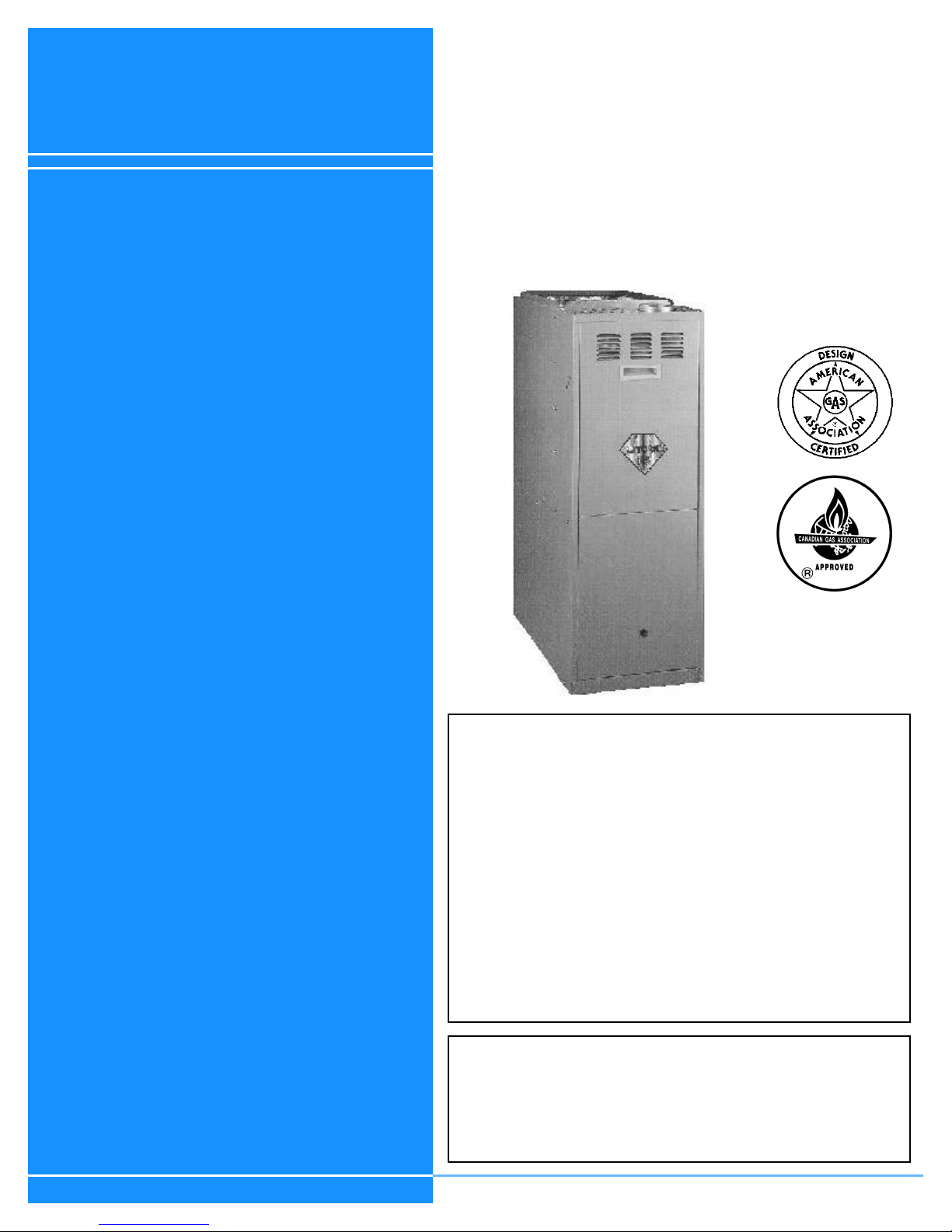
Luxaire G8D-UH, G8D-DN Installation Instructions Manual
INSTALLATION
TWO-STAGE
MID-EFFICIENCY GAS-FIRED
INSTRUCTION
CONTENTS
GENERAL INFORMATION. . . . . . . . . . . . . . . . . . . . . . . . . 3
UNIT INSTALLATION . . . . . . . . . . . . . . . . . . . . . . . . . . . . . 5
VENTING. . . . . . . . . . . . . . . . . . . . . . . . . . . . . . . . . . . . . . . 6
UPFLOW/HORIZONTAL MODELS - . . . . . . . . . . . . . . . . 10
FILTERS INSTALLATION . . . . . . . . . . . . . . . . . . . . . . . . 10
UPFLOW/HORIZONTAL MODELS - . . . . . . . . . . . . . . . . 11
TUBULAR HEAT EXCHANGER SERIES
MODELS: P*DU & G8D-UH (Upflow / Horizontal)
P*DD & G8D-DN (Downflow)
57 - 120 MBH INPUT
DOWNFLOW MODEL APPLICATION . . . . . . . . . . . . . . . 12
OPERATION AND MAINTENANCE. . . . . . . . . . . . . . . . . 23
TROUBLESHOOTING . . . . . . . . . . . . . . . . . . . . . . . . . . . 26
FURNACE ACCESSORIES . . . . . . . . . . . . . . . . . . . . . . . 28
SEQUENCE OF OPERATION . . . . . . . . . . . . . . . . . . . . . 29
WIRING DIAGRAM - UPFLOW / HORIZONTAL . . . . . . . 30
WIRING DIAGRAM - DOWNFLOW . . . . . . . . . . . . . . . . . 31
CAUTION: READ ALL SAFETY GUIDES BEFORE YOU
START TO INSTALL YOUR FURNACE.
SAVE THIS MANUAL
FOR YOUR SAFETY
WHAT TO DO IF YOU SMELL GAS
• Do not try to light any appliance.
• Open windows.
• Do not touch any electrical switch;do not use any phone in
your building.
• Extinguish any open flame.
• Immediately call your gas supplier from a neighbor's phone.
Follow the gas supplier's instructions.
• If you cannot reach your gas supplier, call the fire department.
FOR YOUR SAFETY
Do not store or use gasoline or other flammable vapors and liquids in the vicinity of this or any other appliance.
035-14527-000 REV A (599) Form 650.77-N3U
035-14527-000 REV A (599) Form 650.77-N3U
CONTENTS
GENERAL INFORMATION . . . . . . . . . . . . . . . . . . . . . . . . . 3
DESCRIPTION . . . . . . . . . . . . . . . . . . . . . . . . . . . . . . . . . . . . . . 3
INSPECTION . . . . . . . . . . . . . . . . . . . . . . . . . . . . . . . . . . . . . . . 3
IMPROPER INSTALLATION MAY CREATE A
CONDITION WHERE THE OPERATION OF THE
PRODUCT COULD CAUSE PERSONAL INJURY
OR PROPERTY DAMAGE.
IMPROPER INSTALLATION, ADJUSTMENT,
ALTERATION, SERVICE OR MAINTENANCE
CAN CAUSE INJURY OR PROPERTY DAMAGE.
REFER TO THIS MANUAL FOR ASSISTANCE
NOTES, CAUTIONS & WARNINGS. . . . . . . . . . . . . . . . . . . . . . 3
LIMITATIONS AND LOCATION . . . . . . . . . . . . . . . . . . . . . . . . . 3
UNIT INSTALLATION . . . . . . . . . . . . . . . . . . . . . . . . . . . . . 5
COMBUSTION AIR. . . . . . . . . . . . . . . . . . . . . . . . . . . . . . . . . . . 5
VENTING . . . . . . . . . . . . . . . . . . . . . . . . . . . . . . . . . . . . . . . 6
CATEGORY I VERTICAL VENTING . . . . . . . . . . . . . . . . . . . . . 6
VENT SAFETY CHECK PROCEDURE . . . . . . . . . . . . . . . . . . . 9
DUCTWORK . . . . . . . . . . . . . . . . . . . . . . . . . . . . . . . . . . . . . . . . 9
OR ADDITIONAL INFORMATION, CONSULT A
QUALIFIED INSTALLER, SERVICE AGENCY OR
THE GAS SUPPLIER.
UPFLOW/HORIZONTAL MODELS -. . . . . . . . . . . . . . . . . 10
UPFLOW APPLICATION . . . . . . . . . . . . . . . . . . . . . . . . . . . . . 10
FILTERS INSTALLATION . . . . . . . . . . . . . . . . . . . . . . . . . 10
(UPFLOW/HORIZONTAL) . . . . . . . . . . . . . . . . . . . . . . . . . . . . 10
UPFLOW/HORIZONTAL MODELS -. . . . . . . . . . . . . . . . . 11
HORIZONTAL APPLICATION . . . . . . . . . . . . . . . . . . . . . . . . . 11
THIS PRODUCT MUST BE INSTALLED IN
ATTIC INSTALLATION . . . . . . . . . . . . . . . . . . . . . . . . . . . . . . . 12
CRAWL SPACE INSTALLATION . . . . . . . . . . . . . . . . . . . . . . . 12
STRICT COMPLIANCE WITH THE ENCLOSED
INSTALLATION INSTRUCTIONS AND ANY
APPLICABLE LOCAL, STATE, AND NATIONAL
CODES INCLUDING BUT NOT LIMITED TO,
BUILDING, ELECTRICAL AND MECHANICAL
CODES.
The furnace area must not be used as a broom
closet or for any other storage purposes, as a fire
hazard bay be created. Never store items such as
the following on, near or in contact with the furnace.
1. Spray or aerosol cans, rags, brooms, dust mops,
vacuum cleaners or other cleaning tools.
2. Soap powders, bleaches, waxes or other cleaning
compounds; plastic items or containers; gasoline,
kerosene, cigarette lighter fluid, dry cleaning fluids
or other volatile fluid.
3. Paint thinners and other painting compounds.
DOWNFLOW MODEL APPLICATION . . . . . . . . . . . . . . . 12
DOWNFLOW FILTERS . . . . . . . . . . . . . . . . . . . . . . . . . . . . . . 12
SUPPLY AIR DUCTS. . . . . . . . . . . . . . . . . . . . . . . . . . . . . . . . 13
GAS PIPING . . . . . . . . . . . . . . . . . . . . . . . . . . . . . . . . . . . . . . . 13
ELECTRICAL POWER CONNECTION . . . . . . . . . . . . . . . . . . 14
ELECTRICAL CONTROL CONNECTIONS . . . . . . . . . . . . . . . 14
SAFETY CONTROLS. . . . . . . . . . . . . . . . . . . . . . . . . . . . . . . . 16
START-UP AND ADJUSTMENTS . . . . . . . . . . . . . . . . . . . . . . 16
IGNITION SYSTEM CHECKOUT/ADJUSTMENT . . . . . . . . . . 17
CHECKING GAS INPUT. . . . . . . . . . . . . . . . . . . . . . . . . . . . . . 17
ADJUSTMENT OF MANIFOLD GAS PRESSURE . . . . . . . . . . 18
ADJUSTMENT OF TEMPERATURE RISE . . . . . . . . . . . . . . . 19
ADJUSTMENT OF FAN-OFF CONTROL SETTINGS . . . . . . . 19
ACCESSORY CONNECTIONS . . . . . . . . . . . . . . . . . . . . . . . . 20
OPERATION AND MAINTENANCE . . . . . . . . . . . . . . . . . 23
SEQUENCE OF OPERATION . . . . . . . . . . . . . . . . . . . . . . . . . 23
INTERMITTENT BLOWER - COOLING. . . . . . . . . . . . . . . . . . 23
HEATING OPERATIONAL SEQUENCE . . . . . . . . . . . . . . . . . 23
MAINTENANCE . . . . . . . . . . . . . . . . . . . . . . . . . . . . . . . . . . . . 24
BLOWER CARE . . . . . . . . . . . . . . . . . . . . . . . . . . . . . . . . . . . . 24
CLEANING THE HEAT EXCHANGER. . . . . . . . . . . . . . . . . . . 25
TROUBLESHOOTING . . . . . . . . . . . . . . . . . . . . . . . . . . . . 26
FURNACE CONTROL DIAGNOSTICS . . . . . . . . . . . . . . . . . . 26
FURNACE ACCESSORIES . . . . . . . . . . . . . . . . . . . . . . . 28
4. Paper bags, boxes or other paper products
Never operate the furnace with the blower door
removed. To do so could result in serious personal
injury and/or equipment damage.
2 Unitary Products Group
SEQUENCE OF OPERATION . . . . . . . . . . . . . . . . . . . . . . 29
WIRING DIAGRAM - UPFLOW / HORIZONTAL. . . . . . . . 30
WIRING DIAGRAM - DOWNFLOW . . . . . . . . . . . . . . . . . 31
035-14527-000 REV A (599) Form 650.77-N3U
GENERAL INFORMATION
DESCRIPTION
This Category I furnace is designed for installation in a residential or commercial application. A Category I furnace has a
fan assisted combustion system equipped with an integral
mechanical means to draw products of combustion through
the combustion chamber and heat exchanger. It may be
installed in a basement, garage, equipment room, alcove,
attic or any other indoor location where all required clearances to combustibles and other restrictions are met. It is
designed for natural gas-fired operation, but may be converted to propane (LP).
High altitude and propane (LP) changes or conversions
required in order for the appliance to satisfactorily meet the
application must be made by an authorized distributor, dealer,
licensed technician or other qualified agency, using factory
specified and/or approved parts.
Upflow/horizontal furnaces and downflow furnaces may be
used only as Category I units.
The furnace must be installed so that all electrical components are protected from water.
INSPECTION
As soon as a unit is received, it should be inspected for possible damage during transit. If the damage is evident, the
extent of the damage should be noted on the carrier's freight
bill.
damage may occur if installation procedures are not handled
properly.
Each furnace in this series is a Category I furnace,
suitable for common venting with other gas-fired
appliances as allowed by the National Fuel Gas
Code, NFPA 54/ANSI Z223.1-latest edition
This appliance is not to be used for temporary
heating of buildings or structures under construction.
Do not install this furnace in a corrosive or contaminated atmosphere.
Do not install this furnace in a mobile home or recreational vehicle.
Furnaces shall not be installed directly on carpeting, tile or other combustible material other than
wood flooring.
LIMITATIONS AND LOCATION
This furnace should be installed in accordance with all
national/local building/safety codes and requirements, or in
the absence of local codes, with the National Fuel Gas Code,
ANSI Z223.1 - (latest edition) or, in Canada, CAN/CGA
B149.1 or.2 - (latest edition), and other applicable codes.
A separate request for inspection by the carrier's agent
should be made in writing. Also, before installation, the unit
should be checked for screws or bolts which may have loosened in transit.
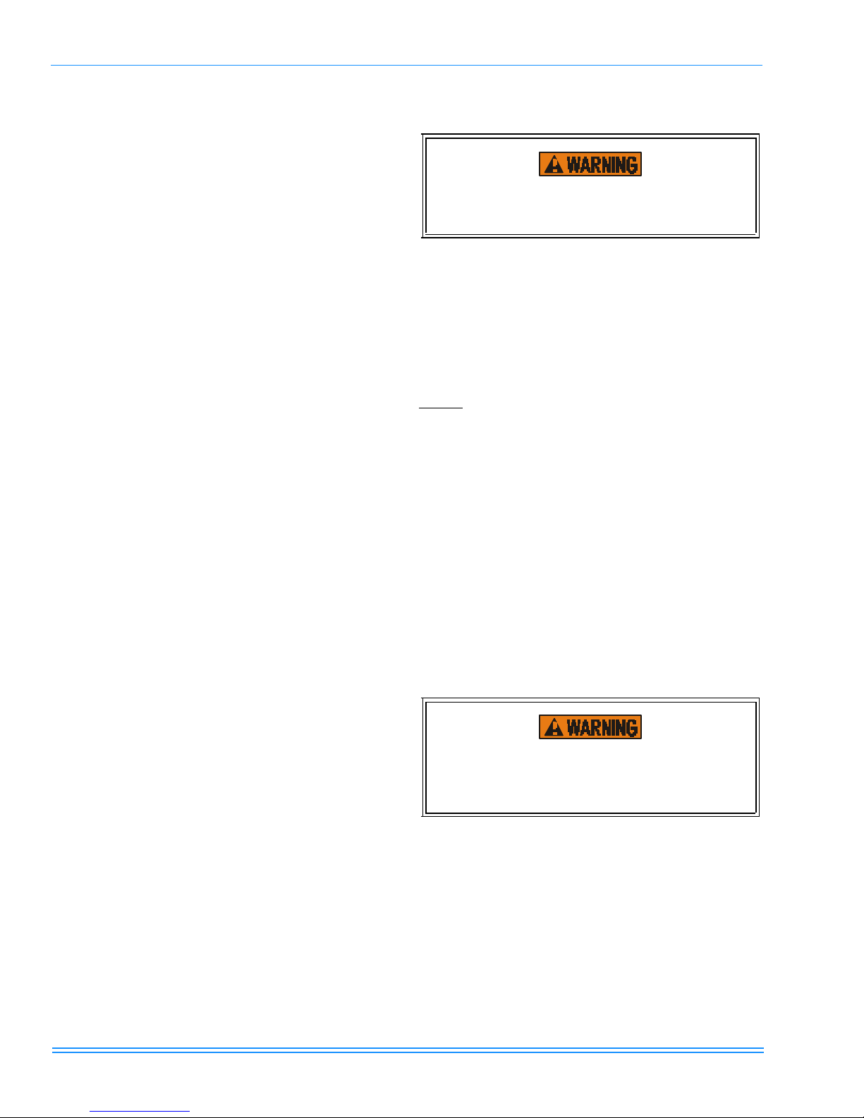
NOTES, CAUTIONS & WARNINGS
The installer should pay particular attention to the words:
NOTE, CAUTION and WARNING. NOTES are intended to
clarify or make the installation easier. CAUTIONS are given
to prevent equipment damage. WARNINGS are given to alert
the installer that personal injury and/or equipment or property
Use only the type of gas approved for this furnace; refer to
the furnace rating plate.
Only use natural gas in furnaces designed for natural gas. Only use propane (LP) gas for furnaces
that have been properly converted to use propane
(LP) gas. Do not use this furnace with butane.
Using wrong gas could create a hazard, resulting
in damage, injury or death.
For installations above 2,000 feet, reduce input 4% for each
1,000 feet above sea level. Canadian installations must be
derated 10% for elevations from 2,000 ft. to 4,500 ft. See
Form 650.74-N1.1V for information to properly derate furnace.
In the U.S. only, furnace shall not be connected to a chimney
flue serving a separate appliance designed to burn solid fuel.
Unitary Products Group 3
035-14527-000 REV A (599) Form 650.77-N3U
Check the rating plate and power supply to be sure that electrical characteristics match. All models use nominal 115 vac,
1phase, 60 Hz. power supply.
A furnace installed in a residential garage must be located so
that all burners and burner ignition devices are located no
less than 18" above the garage floor, and located or protected to prevent damage by vehicles.
The size of the unit should be based on an acceptable heat
loss calculation for the structure. ACCA, Manual J or other
approved methods may be used.
The furnace should be located using these guidelines:
1. Where a minimum amount of vent piping and elbows will
be required.
2. As centralized with the air distribution as possible.
3. Where adequate combustion air will be available.
4. In an area where ventilation facilities provide for safe limits of ambient temperature under normal operating conditions.
5. Where it will not interfere with proper air circulation in the
confined space.
6. Where the vent will not be blocked or restricted.
7. Where sufficient space is provided to allow proper service access. Minimum recommended service clearances
are as follows:
• Twenty-four (24) inches between the front of the fur-
nace and an adjacent wall or another appliance,
when access is required for servicing and cleaning.
• Eighteen (18) inches at the side where access is
required for passage to the front when servicing or
for inspection or replacement of flue/vent connections.
8. Where it will not interfere with the cleaning, servicing or
removal of other appliances.
9. Where the following minimum clearances (in inches) to
combustibles can be maintained: (Refer to Table1 on
page4).
TABLE 1: UNIT CLEARANCES TO COMBUSTIBLES
UPFLOW / HORIZONTAL MODELS - (P*DU & G8D—UH)
APPLICATION TOP FRONT REAR
UPFLOW 1 6 0 0
UPFLOW
B-VENT
HORIZONTAL
HORIZONTAL
B-VENT
DOWNFLOW MODELS (P&DD & G8D—DN)
APPLICATION TOP FRONT REAR
DOWNFLOW 1 6 0 0
DOWNFLOW
B-VENT
1.
14-1/2” cabinet models only - all other units “0” clearance
2.
14-1/2” cabinet left airflow applications only - all other units and all right hand air flow applications “0” clearance.
3.
Special floor base or air conditioning coil required for use on combustible floor.
4.
Line contact only permitted between lines formed by the intersection of the rear panel and side panel (top in horizontal position)
of the furnace jacket and building joists, studs or framing.
1 3 0 0 0 1 COMBUSTIBLE YES YES YES NO
2
6 0 1 0 6 COMBUSTIBLE NO YES YES
3
0 3 0 1 0 1 COMBUSTIBLE NO YES YES
1 3 0 0 0 1
LEFT
SIDE
LEFT
SIDE
RIGHT
SIDE
1
3
RIGHT
SIDE
1
3
FLUE
FLUE
FLOOR/
BOTTOM
6 COMBUSTIBLE YES YES YES NO
FLOOR/
BOTTOM
6
1"
1"
4
4
CLOSET ALCOVE ATTIC
CLOSET ALCOVE ATTIC
YES YES YES NO
YES YES YES NO
LINE
CONTACT
YES
YES
LINE
CONTACT
3
3
4 Unitary Products Group
035-14527-000 REV A (599) Form 650.77-N3U
UNIT INSTALLATION
COMBUSTION AIR
All installations must comply with Section 5.3, Air for Combustion and Ventilation of the National Fuel Gas Code, ANSI
Z223.1 or Sections 7.2, 7.3 or 7.4 of CAN/CGA B149.1 or.2
Installation Code - latest editions.
An unconfined space: is not less than 50 cubic feet per
1000 Btu/hr input rating for all appliances installed in that
area.
Rooms communicating directly with the space containing the
appliances are considered part of the unconfined space, if
openings are not furnished with doors.
A confined space: is an area with less than 50 cubic feet
per 1000 Btu/hr input rating for all appliances installed in that
area.
The following must be considered to obtain proper air for
combustion and ventilation in confined spaces.
Air Source from Inside the Building -
Two permanent openings, one within 12 inches of the top of
the confined space and one within 12 inches of the bottom,
shall each have a free area of not less than one square inch
per 1,000 Btuh of total input rating of all appliances located in
the space. The openings shall communicate freely with interior areas having adequate infiltration from the outside.
NOTE : At least 100 square inches free area shall be used
for each opening.
Air Source from Outdoors -
1. Two permanent openings, one within 12 inches of the
top of the confined space and one within 12 inches of the
bottom, shall communicate directly, or by means of
ducts, with the outdoors or to such crawl or attic spaces
that freely communicate with the outdoors.
a. Vertical Ducts - Each opening must have a free
area of not less than one square inch per 4,000 Btuh
of total input of all appliances located in the space.
EXAMPLE:
NOTE: Ducts must have the same cross-sectional area as
the free area in the opening to which they are connected. The
minimum dimension of rectangular ducts shall be three
inches.
2. One permanent opening, commencing within 12 inches
of the top of the enclosure shall be permitted where the
equipment has clearances of at least 1 inch from the
sides and back and 6 inches from the front of the appliance. The opening shall communicate through a vertical
or horizontal duct to the outdoors, or spaces (crawl or
attic) that freely communicate with the outdoors and shall
have a minimum free area of:
a. 1 sq. in. per 3000 Btu per hr of the total input rating
of all equipment located in the enclosure.
b. Not less than the sum of the areas of all vent con-
nectors in the confined space.
3. Louvers, Grilles and Screens
a. In calculating free area, consideration must be given
to the blocking effects of louvers, grilles and
screens.
To estimate free area of a specific louver or grille (Refer to
Table2 on page5)..
TABLE 2: ESTIMATED FREE AREA
Wood or Metal
Louvers or Grilles
2
Screens
1.
Do not use less than 1/4 in. mesh
2.
Free area or louvers an grilles varies widely; installer
should follow louver or grille manufacturer’s instructions.
Wood 20-25%
Metal 60-70%
1/4 in. mesh or larger 100%
NOTE: If mechanically operated louvers are used, a means
to prevent main burner ignition and operation must be provided should louvers close during startup or operation.
Special Combustion and Ventilation Considerations
Operation of a mechanical exhaust, such as an exhaust fan,
kitchen ventilation system, clothes dryer or fireplace may create conditions requiring special attention to avoid unsatisfactory operation of gas appliances.
1
1
Total Input of All Appliances
= Square Inches Free Area
4000
b. Horizontal Ducts - Each opening must have a free
area of not less than one square inch per 2,000 Btuh
of total input of all appliances located in the space.
Unitary Products Group 5
Specially Engineered Installations
The above requirements shall be permitted to be waived
where special engineering, approved by the authority having
jurisdiction, provides an adequate supply of air for combustion, ventilation and dilution of flue gases.
035-14527-000 REV A (599) Form 650.77-N3U
Combustion Air Quality
The recommended source of combustion air is to use the outdoor air supply. Excessive exposure to contaminated combustion air will result in safety and performance related
problems. However, the use of indoor air in most applications
is acceptable, except as follows:
1. If the furnace is installed in a confined space it is recommended that the necessary combustion air come from
the outdoors by way of attic, crawl space, air duct or
direct opening.
2. If outdoor combustion air is used, there must be no exposure to the installations or substances listed in 3" below.
3. The following types of installations may require OUTDOOR AIR for combustion, due to chemical exposure.
a. Commercial buildings
b. Buildings with indoor pools
c. Furnaces installed in laundry rooms
d. Furnaces installed in hobby or craft rooms
e. Furnaces installed near chemical storage areas
Exposure to the following substances in the combustion air
supply may also require OUTDOOR AIR for combustion.
VENTING
It is the responsibility of the installer to verify
proper vent system operation.
CATEGORY I VERTICAL VENTING
Category I venting consists of vertically venting one or more
appliances in B-vent or masonry chimney (as allowed), using
single wall metal pipe or B-vent connectors. Type B-vent system extends in a general vertical direction and does not contain offsets exceeding 45 degrees, except that a vent system
having not more than one 60-degree offset is permitted.
NOTE: This appliance may be common vented with another
gas appliance as allowed by the following codes and standards.
The furnace rating plate lists the maximum vent gas temperature. This temperature must be used to select appropriate
venting materials and clearances. A typical example is shown
below.
f. Permanent wave solutions
g. Chlorinated waxes and cleaners
h. Chlorine based swimming pool chemicals
i. Water softening chemicals
j. De-icing salts or chemicals
k. Carbon tetrachloride
l. Halogen type refrigerants
m. Cleaning solvents (such as perchloroethylene)
n. Printing inks, paint removers, varnishes, etc.
o. Hydrochloric acids
p. Cements and glues
q. Antistatic fabric softeners for clothes dryers
r. Masonry acid washing chemicals
CATEGORY 1 - 450 F. MAX. VENT TEMP.
All installations must be vented in accordance with the
National Fuel Gas Code, NFPA 54/ANSI Z223.1 - latest edition. For reference, the National Fuel Gas Code Handbook,
available from NFPA (item JP-54HB96) is recommended.
The appliance must also be vented in compliance with all
local utility and code requirements. In Canada, the furnace
must be vented in accordance with the National Standard of
Canada, CAN/CGA-B149.1 and.2 - latest editions.
A furnace shall not be connected to a chimney flue
serving a separate appliance designed to burn
solid fuel.
6 Unitary Products Group
035-14527-000 REV A (599) Form 650.77-N3U
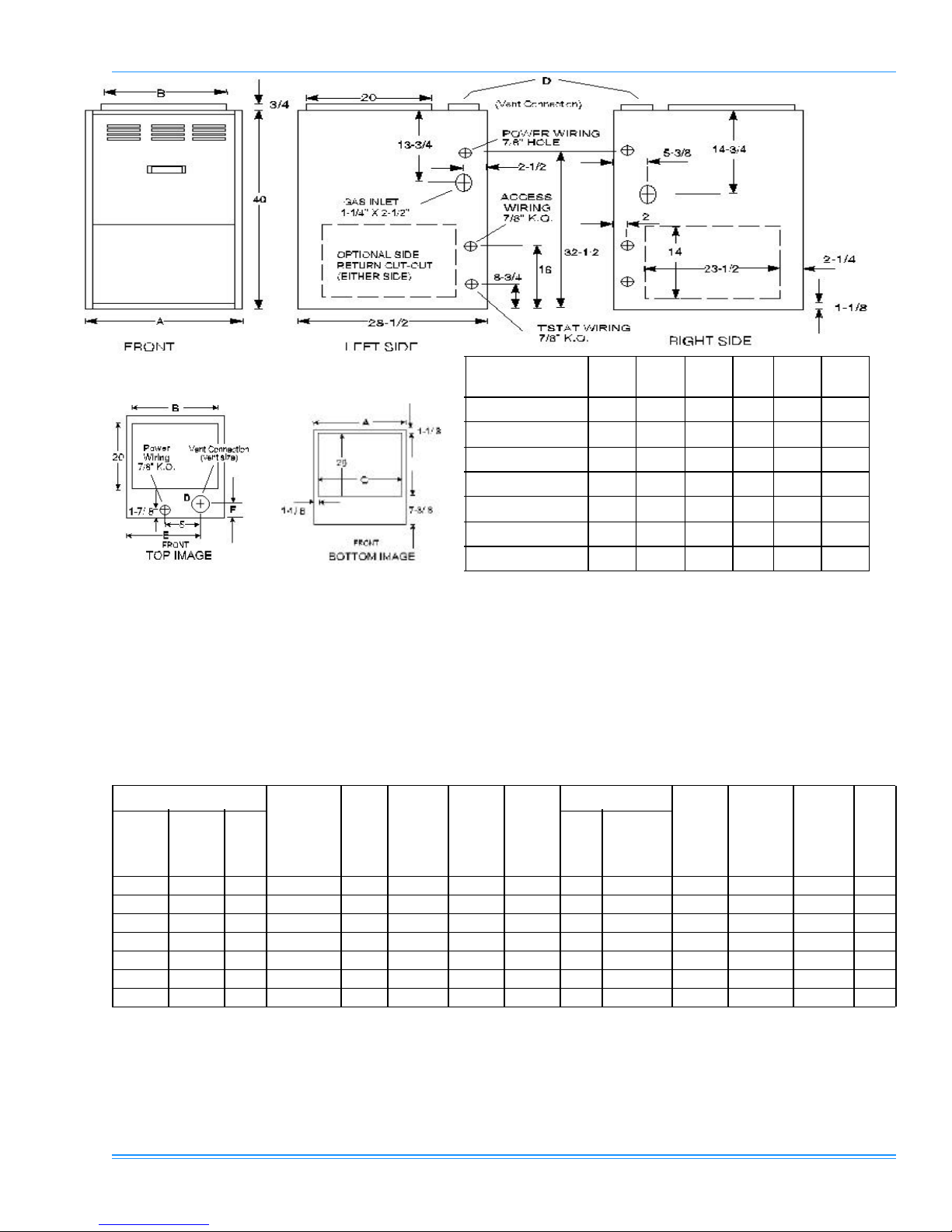
Models P*DU &
G8D—UH
A B C D E F
57 / 46 / 800 / “A” 14-1/2 13-1/4 10-1/8 3 10-1/8 4-3/16
80 / 64 / 1200 / “A” 14-1/2 13-1/4 10-1/8 4 10-1/8 3-3/4
80 / 64 / 1600 / “B” 17-1/2 16-1/4 13-1/8 4 11-5/8 3-3/4
100 / 80 / 1200 / “B” 17-1/2 16-1/4 13-1/8 4 11-5/8 3-3/4
100 / 80 2000 / “C” 21 19-3/4 16-5/8 4 13-3/8 3-3/4
120 / 92 / 1600 / “C” 21 19-3/4 16-5/8 4 13-3/8 3-3/4
120 / 80 / 2000 / “C” 21 19-3/4 16-5/8 4 13-3/8 3-3/4
* Input / Output / CFM / Cabinet
All dimensions are in inches and are approximate
FIGURE 1: 2-STAGE UPFLOW/HORIZONTAL FURNACE DIMENSIONS
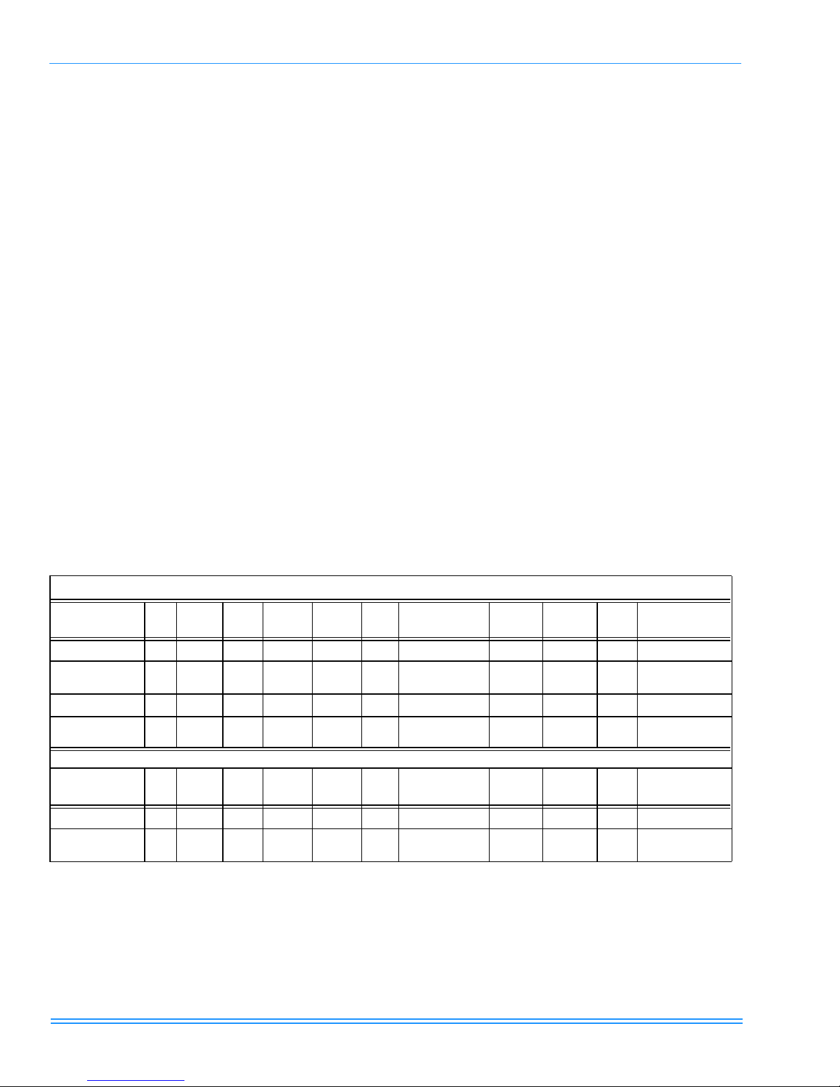
TABLE 3: 2-STAGE UPFLOW/HORIZONTAL RATINGS & PHYSICAL/ELECTRICAL DATA
MODELS P* DU & G8D--UH CAB INE T
INPU T
MBH H/L
OUTPUT
MBH H/L
NOM.
CFM
WIDTH (IN.)
57/42 46/34 800 “A” 14-1/2 80 25 - 55 35 - 65 165 1/4 9 x 6 9.0 20 14 105
80/59 64/48 1200 “A” 14-1/2 80 30 - 60 40 - 70 175 1/3 10 x 7 9.0 20 14 117
80/59 64/48 1600 “B” 17-1/2 80 25 - 55 25 - 55 160 3/4 11 x 8 12.0 20 14 126
100/65 80/53 1200 “B” 17-1/2 80 25 - 55 40 - 70 170 1/2 10 x 8 12.0 20 14 128
100/65 80/53 2000 “C” 21 80 25 - 55 30 - 60 160 1 11 x 10 12.0 20 14 145
120/78 96/64 1600 “C” 21 80 25 - 55 45 - 75 180 1/2 10 x 10 12.0 20 14 145
120/78 96/64 2000 “C” 21 80 25 - 55 35 - 65 170 1 11 x 10 12.0 20 14 147
1.
AFUE numbers are determined in accordance with DOE test procedures.
2.
Wire size and overcurrent protection must comply with the National Electrical Code (NFPA-70-latest edition).
• For altitudes above 2,000 ft., reduce capacity 4% for each 1,000 ft. above sea level. Refer to Form 650.74-N1.1V.
• Wire size based on copper conductors, 60° C, 3% voltage drop.
• Continuous return air temperature must not be below 55° F.
AFU E
1
LOW FIRE
TEMP RISE
HIGH
°F
FIRE
TEMP
RISE °F
MAX.
OUTLET
AIR TEMP
°F
BLOWER TOTAL
HP SIZE (IN)
UNIT
AMPS
MAX.
OVER-
CUR REN T
PROTECT
MIN WIRE
(AWG) @
2
ONE WA Y
SIZE
75 FT.
2
OPER
WGT.
(L BS )
Unitary Products Group 7
035-14527-000 REV A (599) Form 650.77-N3U
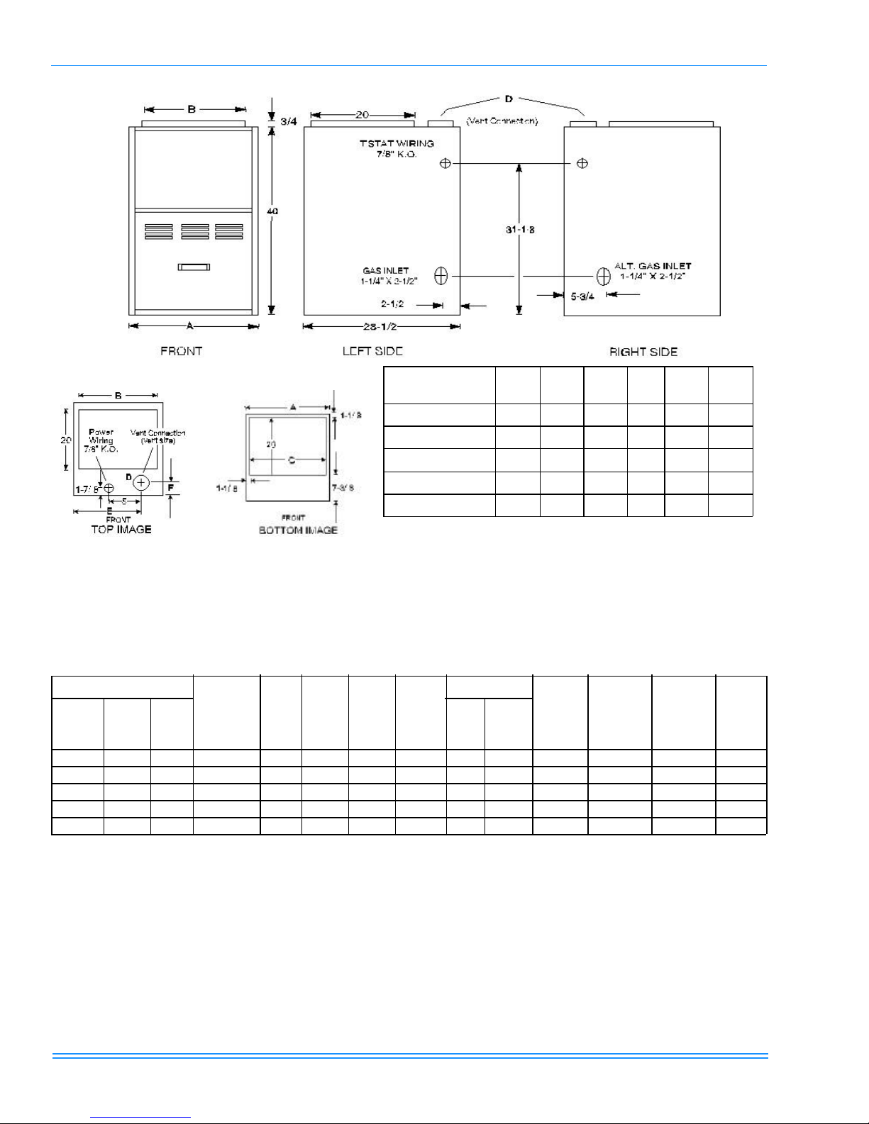
Models P*DD &
G8D—DN
A B C D E F
57 / 46 / 800 / “A” 14-1/2 13-1/4 12-1/4 3 10-1/8 4-3/16
80 / 64 / 1200 / “A” 14-1/2 13-1/4 12-1/4 4 10-1/8 3-3/4
80 / 64 / 1600 / “B” 17-1/2 16-1/4 15-1/4 4 11-5/8 3-3/4
100 / 80 / 1200 / “B” 17-1/2 16-1/4 15-1/4 4 11-5/8 3-3/4
120 / 80 / 2000 / “C” 21 19-3/4 18-3/4 4 13-3/8 3-3/4
* Input / Output / CFM / Cabinet
All dimensions are in inches and are approximate.
FIGURE 2 : 2-STAGE DOWNFLOW FURNACE DIMENSIONS
TABLE 4: 2-STAGE RATINGS & PHYSICAL/ELECTRICAL DATA
M ODE LS P *DD & G8D--DN CABI NET
INPUT
MBH
H/L
OU TPU T
MBH H /L
NOM.
CFM
WIDT H (IN.)
57/42 46/34 800 “A” 14-1/2” 80 20 - 50 30 - 60 160 1/4 10 x 6 9.0 20 14 110
80/59 64/48 1200 “A” 14-1/2” 80 25 - 55 30 - 60 160 1/2 10 x 8 12.0 20 14 120
80/59 64/48 1600 “B” 17-1/2” 80 20 - 50 25 - 55 160 3/4 11 x 10 12.0 20 14 130
100/65 80/52 1200 “B” 17-1/2” 80 25 - 55 40 - 70 170 1/2 10 x 8 12.0 20 14 125
120/78 96/64 2000 “C” 21” 80 25 - 55 30 - 60 160 1 11 x 10 12.0 20 14 150
1.
AFUE numbers are determined in accordance with DOE test procedures.
2.
Wire size and overcurrent protection must comply with the National Electrical Code (NFPA-70-latest edition).
• For altitudes above 2,000 ft., reduce capacity 4% for each 1,000 ft. above sea level. Refer to Form 650.74-N1.1V.
• Wire size based on copper conductors, 60° C, 3% voltage drop.
• Continuous return air temperature must not be below 55° F.
A FUE
1
LOW
FIRE
TEMP
R IS E °F
HIGH
FIRE
TEMP
R IS E °F
MAX.
OUT LE T
AIR T EMP
°F
B LOWE R TOTAL
HP SI ZE (IN)
AMPS
UNIT
MAX. OVER-
CUR REN T
PROTECT
MIN WIRE
SIZE (AWG)
2
@ 75 F T.
ONE WA Y
2
OPER
WGT.
(L BS )
8 Unitary Products Group

035-14527-000 REV A (599) Form 650.77-N3U
VENT SAFETY CHECK PROCEDURE
If this furnace is replacing a common-vented furnace, it may be necessary to resize the existing
vent line and chimney to prevent oversizing problems for the new combination of units. Refer to the
National Fuel Gas Code, ANSI Z223.1 or CAN/
CGA B149.1 or.2 Installation Code - latest editions.
The following steps shall be followed with each appliance
connected to the venting system placed in operation, while
any other appliances connected to the common venting system are not in operation.
1. Seal any unused openings in the common venting system.
2. Inspect venting system for proper size and horizontal
pitch, as required in the National Fuel Gas Code ANSI
Z223.1 or the CAN/CGA B149 Installation Codes and
these instructions. Determine that there is no blockage
or restriction, leakage, corrosion or other deficiencies
which could cause an unsafe condition.
3. Insofar as is practical, close all building doors and windows and all doors between the space in which the appliance(s) connected to the venting system are located and
other spaces of the building. Turn on clothes dryers and
any other appliances not connected to the common venting system. Turn on any clothes dryers and any appliance not connected to the venting system.
7. If improper venting is observed during any of the above
tests, the venting system must be corrected.
8. Any corrections or resizing of the common venting system must be in accordance with the National Fuel Gas
Code, ANSI Z223.1 or Section 7, Venting Systems and
Air Supply for Appliances, CAN/CGA B149.1 or.2 Installation Code - latest editions. If the common vent system
must be resized, it should be resized to approach the
minimum size as determined using the appropriate
tables in Appendix G of the above codes or the venting
tables supplied with the furnace.
DUCTWORK
The duct system's design and installation must:
1. Handle an air volume appropriate for the served space
and within the operating parameters of the furnace specifications.
2. Be installed in accordance with standards of NFPA
(National Fire Protection Association) as outlined in
NFPA pamphlets 90A and 90B - (latest editions).
3. Create a closed duct system. The supply system must
be connected to the furnace outlet and the return duct
system must be connected to the furnace inlet. Both supply and return duct systems must terminate outside the
space containing the furnace.
4. Generally complete a path for heated or cooled air to circulate through the air conditioning and heating equipment and to and from the conditioned space.
Turn on any exhaust fans, such as range hoods and
bathroom exhausts so they will operate at maximum
speed. Do not operate a summer exhaust fan. Close fireplace dampers.
4. Follow the lighting instructions. Place the appliance
being operated in operation. Adjust thermostat so appliance will operate continuously.
5. Test for draft hood equipped appliance spillage at the
draft hood relief opening after 5 minutes of main burner
operation. Use the flame of a match or candle.
6. After it has been determined that each appliance connected to the venting system properly vents when tested
as outlined above, return doors, windows, exhaust fans,
fireplace dampers and any other gas-burning appliance
to their previous conditions of use.
Unitary Products Group 9
The cooling coil must be installed in the supply air
duct downstream of the furnace.
When the furnace is used in conjunction with a cooling coil,
the furnace must be installed parallel with, or on the upstream
side of the cooling unit to avoid condensation in the primary
heat exchanger.
When a parallel flow arrangement is used, the dampers or
other means used to control air flow must be adequate to prevent chilled air from entering the furnace, and if manually
operated, must be equipped with means to prevent operating
of either unit unless the damper is in the full heat or cool position.
035-14527-000 REV A (599) Form 650.77-N3U
UPFLOW/HORIZONTAL MODELS -
UPFLOW APPLICATION
Supply Plenum Connection
Attach the supply plenum to the furnace outlet duct connection flanges.
This is typically through the use of S
cleat material when a metal plenum is
used. The use of an approved flexible
duct connector is recommended on all
installations. This connection should be
sealed to prevent air leakage.
If a matching cooling coil is used, it
may be placed directly on the furnace
outlet and sealed to prevent leakage.
Follow the coil instructions for installing
the supply plenum.
On all installations without a coil, a removable access panel
is recommended in the outlet duct such that smoke or
reflected light would be observable inside the casing to indicate the presence of leaks in the heat exchanger. This
access cover shall be attached in such a manner as to prevent leaks.
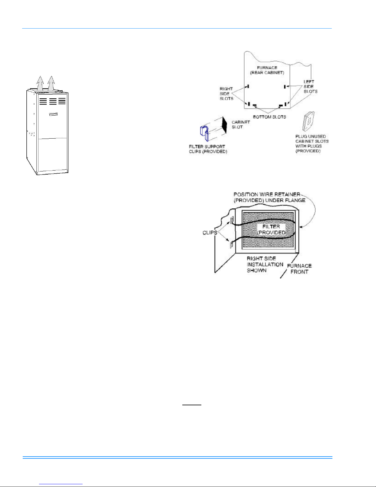
FIGURE 3 : FURNACE FILTER SLOT LOCATIONS
Return Duct Connection
Return air may enter the furnace through the side(s) or bottom depending on the type of application. Return air may not
be connected into the rear panel of the unit. See the specific
type application installation for details. Be sure to see the Filters section of this instruction.
FILTERS INSTALLATION
(UPFLOW/HORIZONTAL)
All applications require the use of a filter. A high velocity filter
and retainer are provided for field installation.
Internal Installation
1. Select desired filter position (left/right side, or bottom).
Remove the corresponding cabinet cut-outs per instructions provided.
2. Install snap-in retainer clips into the corresponding slots
from the outside rear of the cabinet. (Refer to Figure 3
on page10) To prevent cabinet air leaks, install snap-in
plugs (provided) into the unused slots at the outside rear
of the cabinet.
3. Install the wire retainer inside the cabinet. Insert the
open ends of the wire retainer into the clip loops at the
rear of the blower compartment. The retainer wire should
pivot freely like a hinge, on the clips at the rear of the
FIGURE 4 : SIDE FILTER RETAINER PLACEMENT
4. Install the filter(s) provided. Cut filter if necessary to
match air opening in cabinet. Filter should extend
beyond opening edge as much as possible to prevent air
from bypassing the filter. DO NOT remove stiffening rods
from inside the filter. Shorten the rods, if necessary, to
match final filter size.
5. Position the filter between the wire retainer and the cabinet wall (or floor) so it completely covers the cabinet air
opening and secure the filter in place at the front of the
cabinet by fastening the closed (looped) end of the
retainer wire under the flanged edge of the cabinet.
When properly installed the filter should fit flush with all
four sides of the cabinet wall.
NOTE: Air velocity through throw-away type filters may not
exceed 300 feet per minute. All velocities over this require the
use of high velocity filters.
10 Unitary Products Group
 Loading...