

Luxaire FHP180, FHP 240 Installation Manual
INSTALLATION
MANUAL
CONTENTS
GENERAL....................................4
RENEWALPARTS.............................4
INSPECTION . . . . . . . . . . . . . . . . . . . . . . . . . . . . . . . . . 3
PRODUCT NOMENCLATURE. . . . . . . . . . . . . . . . . . . . 3
INSTALLATION...............................3
MAINTENANCE . . . . . . . . . . . . . . . . . . . . . . . . . . . . . . 17
See the following page for a complete Table of Contents.
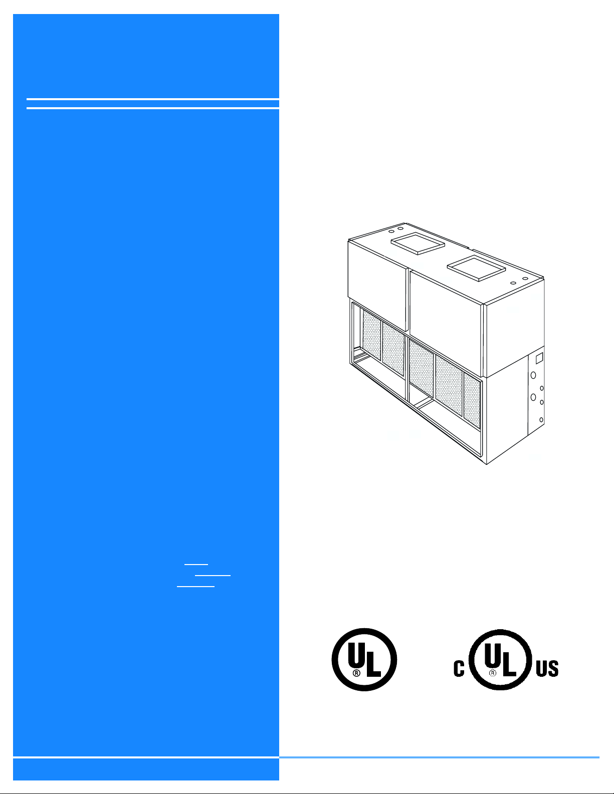
SPLIT-SYSTEM HEAT PUMPS
INDOOR UNITS 4 PIPE
MODELS: FHP180 & 240
NOTES, CAUTIONS AND WARNINGS
Installer should pay particular attention to the words:
NOTE, CAUTION,andWARNING.Notes
clarify or make the installation easier. Cautions
to prevent equipment damage. Warnings
alert installer that personal injury and/or equipment damage may result if installation procedure is not handled
properly.
CAUTION: READ ALL SAFETY GUIDES BEFORE YOU
BEGIN TO INSTALL YOUR UNIT.
SAVE THIS MANUAL
are intended to
are given
are given to
FHP240
SHOWN
035-18200-000-B-1102

TABLE OF CONTENTS
035-18200-000-B-1102
GENERAL.................................3
RENEWALPARTS..........................3
INSPECTION...............................3
INSTALLATION.............................4
RIGGING...................................4
LOCATION .................................4
CLEARANCES ..............................4
DUCT CONNECTIONS .......................11
REFRIGERANTMAINS.......................11
INSTALLINGREFRIGERANTMAINS ............11
DRAINCONNECTION .......................12
SUPPLYAIRBLOWERADJUSTMENT..........12
POWERANDCONTROLWIRING..............15
MAINTENANCE. . ..........................17
INDOORCOIL..............................17
FILTERS..................................17
DRAINPAN................................17
LUBRICATION..............................17
BELTS....................................17
Fig. # Pg. #
8 BASE ACCESSORY FHP180. . . . . . . . . . . . . . . . . . . 10
9 BASE ACCESSORY FHP240. . . . . . . . . . . . . . . . . . . 10
10 SUPPLYAIRPLENUMFHP180.................10
11 SUPPLY AIR PLENUM KNOCKOUTS FHP180 . . . . . 10
12 SUPPLYAIRPLENUMFHP240.................11
13 RECOMMENDEDDRAINPIPING ...............12
14 TYPICAL MOTOR MOUNTING ASSEMBLY . . . . . . . 13
15 HOLE LOCATIONS FOR PRESSURE DROP
READINGS.................................13
16 CFMVSPRESSUREDROP....................14
17 TYPICALFIELDWIRING......................17
18 UNITDIMENSIONSFHP180 ...................18
19 UNITDIMENSIONSFHP240 ...................19
LIST OF TABLES
Tbl. # Pg. #
1 PHYSICALDATA .............................5
LIST OF FIGURES
Fig. # Pg. #
1 PRODUCT NOMENCLATURE . . . . . . . . . . . . . . . . . . . 3
2 UNIT SUSPENSION MOUNTING FHP180 . . . . . . . . . . 6
3 UNIT SUSPENSION MOUNTING FHP240 . . . . . . . . . . 7
4 VERTICAL AND HORIZONTAL APPLICATIONS . . . . . 8
5 ELECTRIC HEAT ACCESSORY. . . . . . . . . . . . . . . . . . 9
6 RETURNAIRGRILLEFHP180..................10
7 RETURNAIRGRILLEFHP240..................10
2 UNIT APPLICATION DATA . . . . . . . . . . . . . . . . . . . . . 5
3 FHP180 UNIT SUSPENSION WEIGHTS (LBS) . . . . . . 6
4 FHP240 UNIT SUSPENSION WEIGHTS (LBS) . . . . . . 7
5 ELEC HEATER DIMENSIONS FHP180 & 240 . . . . . . . 9
6 SUPPLY AIR BLOWER MOTOR PULLEY
ADJUSTMENT...............................13
7 SUPPLY AIR PERFORMANCE FHP180. . . . . . . . . . . 14
8 SUPPLY AIR PERFORMANCE FHP240. . . . . . . . . . . 15
9 ELECTRICAL RATINGS INDOOR UNIT - HEAT PUMP
WITHELECTRICHEAT .......................16
10 FHP180MINIMUMCLEARANCES...............18
2 UnitaryProductsGroup
035-18200-000-B-1102
GENERAL
Every unit includes a well-insulated cabinet, copper
tube/aluminum fin coil with interlaced circuiting
arrangement, 1" throwaway filters, centrifugal blower
with a fixed pitch sheave, and a blower motor with variable p itch sheave.
They also include 2 filter driers, 2 expansion valves
and distributors that are only used during the cooling
cycle plus a check valve to provide the proper flow of
refrigerant through the unit during both the cooling and
heating cycles...
Improper installation may create a condition
where the operation of the product could
cause personal injury or property damage.
The controls include 208/230/460 volt transformer,
blower motor contactor and relay, and a low voltage
terminal block.
The units are shipped in the vertical position ready for
field installation. For horizontal installation, the blower
module can be repositioned in the field as shown on
page 3 for maximum flexibility. *Blower motor and drive
sold separately on FHP240.
RENEWAL PARTS
Refer to the Source One Parts Manual for a complete
listing of replacement parts on this equipment.
All forms referenced in this instruction may be ordered
from:
Standard Register
2101 West Tecumseh Road
Norman, Oklahoma 73069
Toll Free Fax (877) 379-7920
This instruction covers the installation of the indoor
unit. For information on the installation and operation of
the matching outdoor unit, refer to part no. 035-17399-
000.
Installer should pay particular attention to the words:
NOTE, CAUTION and WARNI NG. Notes are intended
to clarify or make the installation easier. Cautions are
given to prevent equipment damage. Warnings are
given to alert the installer that personal injury and/or
equipment damage may result if the installation proce-
dure is not handled properly.
This product must be installed in strict compliance with the enclosed installation instructions and any applicable local, state, and
national codes including but not limited to,
building, electrical and mechanical codes.
INSPECTION
As soon as a unit is received, it should be inspected for
possible damage during transit. If damage is evident,
the extent of the damage should be noted on the carrier’s freight bill. A separate request for inspection by
the carrier’s agent should be made in writing.
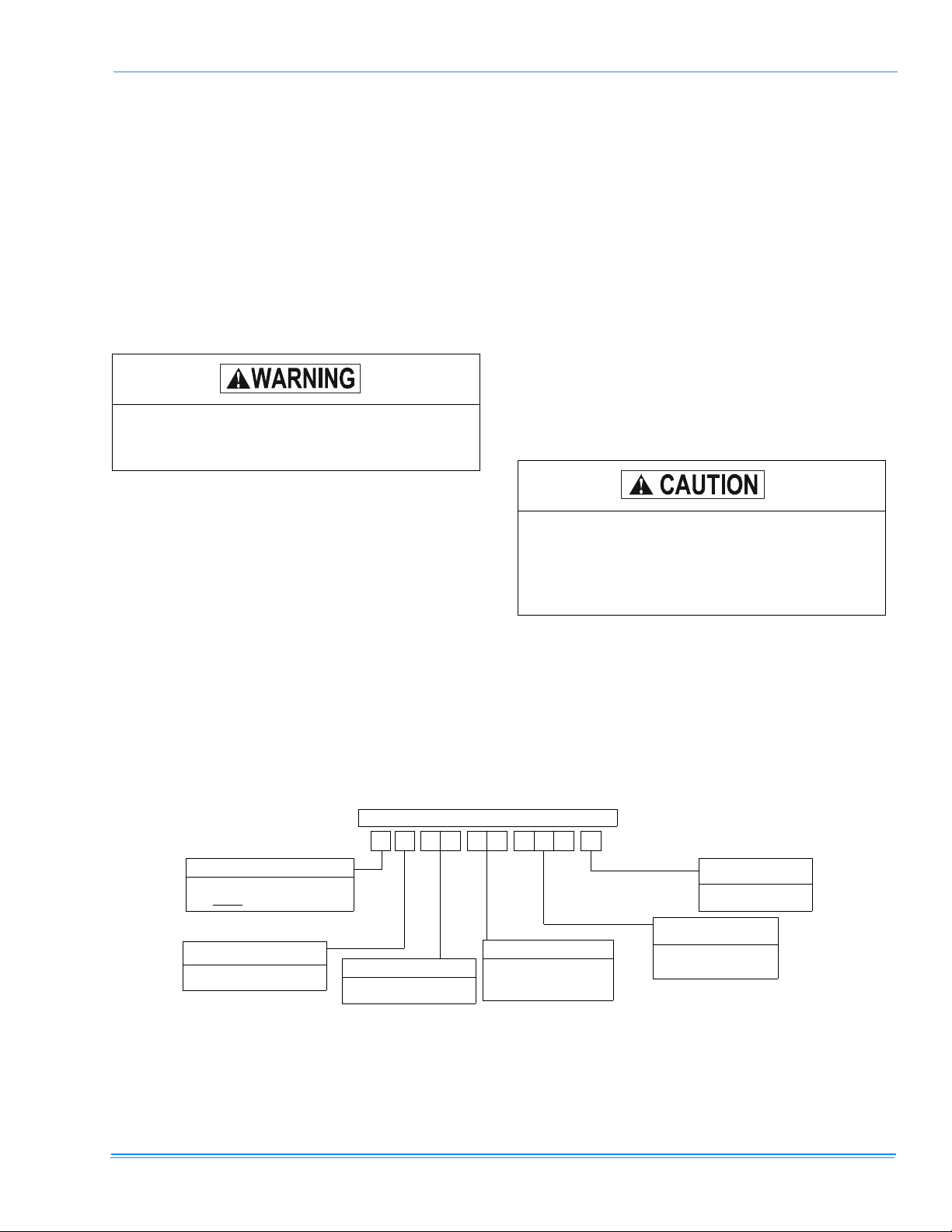
PRODUCT NOMENCLATURE
PRODUCT CATEGORY
F = Split-System Heat Pump
Indoor - 4 Pipe Unit
PRODUCT GENERATION
A = 1st Generation
B = 2nd Generation
E A S E - T 8 A
PRODUCT IDENTIFIER
SE = OUTDOOR UNIT
4 PIPE
1 0
VOLTAGE CODE
= 208/230-3-60
-T
-W= 460-3-60
FACTORY INSTALLED
HEAT
A = No Heat Installed
NOMINAL COOLING
CAPACITY (@ 60 Hz)
15 Ton
180 =
240 = 20 To
n
FIGURE 1: PRODUCT NOMENCLATURE
Unitary Products Group 3
035-18200-000-B-1102
INSTALLATION
LIMITATIONS
Theses units must be installed in accordance with all
national and local safety codes. If no local codes apply,
installation must conform with the appropriate national
code. Units are designed to meet National Safety Code
Standards.Ifcomponentsaretobeaddedtoaunitto
meet local codes, they are to be installed at the
dealer’s and/or the customer’s expense. See Table
for application data.
RIGGING
Be careful when moving the unit. Do not remove any
packaging until the unit is near its final location.
The packaging consists of a bottom wooden skid that
can be lifted with a fork truck from any direction, a plastic bag that covers the entire unit, and strapping that
secures the plastic bag to the bottom skid These units
canberiggedwithslingsunderthebottomskid.
Spreader bars should be used to prevent
slings from crushing the unit panels and
frame.
Before rigging any unit, determine its weight from
TABLE 1. Before rigging a unit for horizontal installation, determine its center of gravity from FIGURE 2 and
FIGURE 4, and make sure that its weight will be distributed equally.
LOCATION
These indoor units are not designed for outdoor installation. They must be located within the building structure, either inside or outside the conditioned space.
The units should be located as close to the outdoor
units as practical and positioned to minimize bends in
the refrigerant piping. Units being installed vertically or
horizontally can be set directly on a floor or platform, or
they can be supported by metal or wooden beams.
Be careful when attaching the hanger rods.
Use a washer with a back-up nut on each rod
and tighten down against the cabinet so they
will not be allowed to turn or slip.
Units being installed horizontally can be suspended
from above. Four 3/8” weld nuts are provided in the unit
frame to accommodate hanger rods. Knockouts must
be removed form the unit panels to expose these weld
nuts. Refer to FIGURE 2 and FIGURE 4, for their location and the individual load on each hanger rod.
CLEARANCES
The clearances listed on unit dimensions drawing (Fig.
18 and 19) are required for the proper service and
operation of the unit.
4 UnitaryProductsGroup
035-18200-000-B-1102
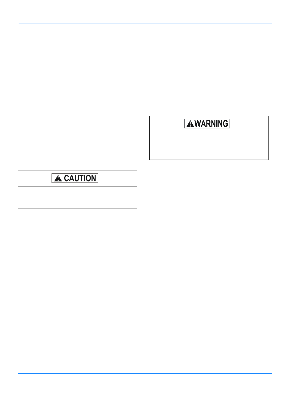
TABLE 1: PHYSICAL DATA
DESCRIPTION
Rows Deep X Rows High
Finned Length - inches
Coil
Face Area - square feet
Tube (Copper) OD - inches
Fins (Aluminum) per inch
Centrifugal Blower (Forward Cur ve) - Qt y Diameter X Width - inches
Blower Motor
1
HP
RPM
Quantity per unit
Filters (Throwaway)
Size (in)
Total Face Area - square feet
Unit Weight (lbs)
Shipping
Operating
Motor & Drive
Accessory Operating Weight (Lbs.)
Electric Heat
Supply Air Plenum
Return Air Grille
Base
1.
Refer to “Blower Motor and Drive Data” table for more information.
3HP
5HP
10 KW
20 KW
30 KW
40 KW
50 KW
UNIT MODEL
FHP180 FHP240
3X32 3X32
54.5 83
12.11 18.44
3/8 3/8
13 13
18 X 18 - 1 15 X 12 - 2
3---
1750 ---
68
20X20X1 20X22X1
16.7 24.1
425 830
435 720
90 90
--- 120
63 --66 126
71 129
--- 132
80 137
114 150
20 15
100 120
TABLE 2: UNIT APPLICATION DATA
APPLICATION LIMITATIONS MIN MAX
VOLTAGE VARIATION (208/230-3-360) 187 253
VOLTAGE VARIATION (460-3-360) 414 506
AMBIENT AIR ON OUTDOOR COIL (COOLING CYCLE) °f45115
AMBIENT AIR ON INDOOR COIL (COOLING CYCLE) °F6886
AMBIENT AIR ON OUTDOOR COIL (HEATING CYCLE) °F070
AMBIENT AIR ON INDOOR COIL (HEATING CYCLE) °F6080
Unitary Products Group 5
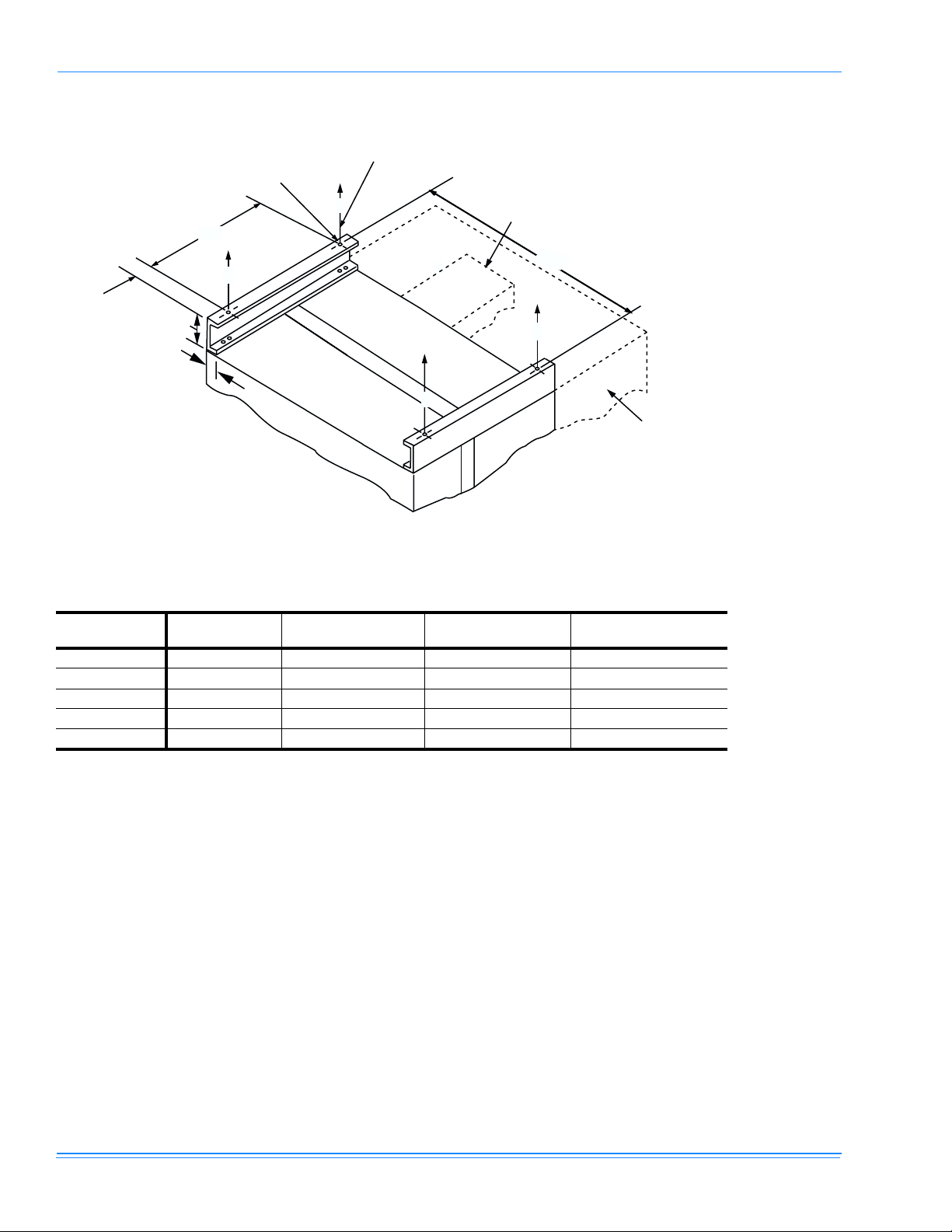
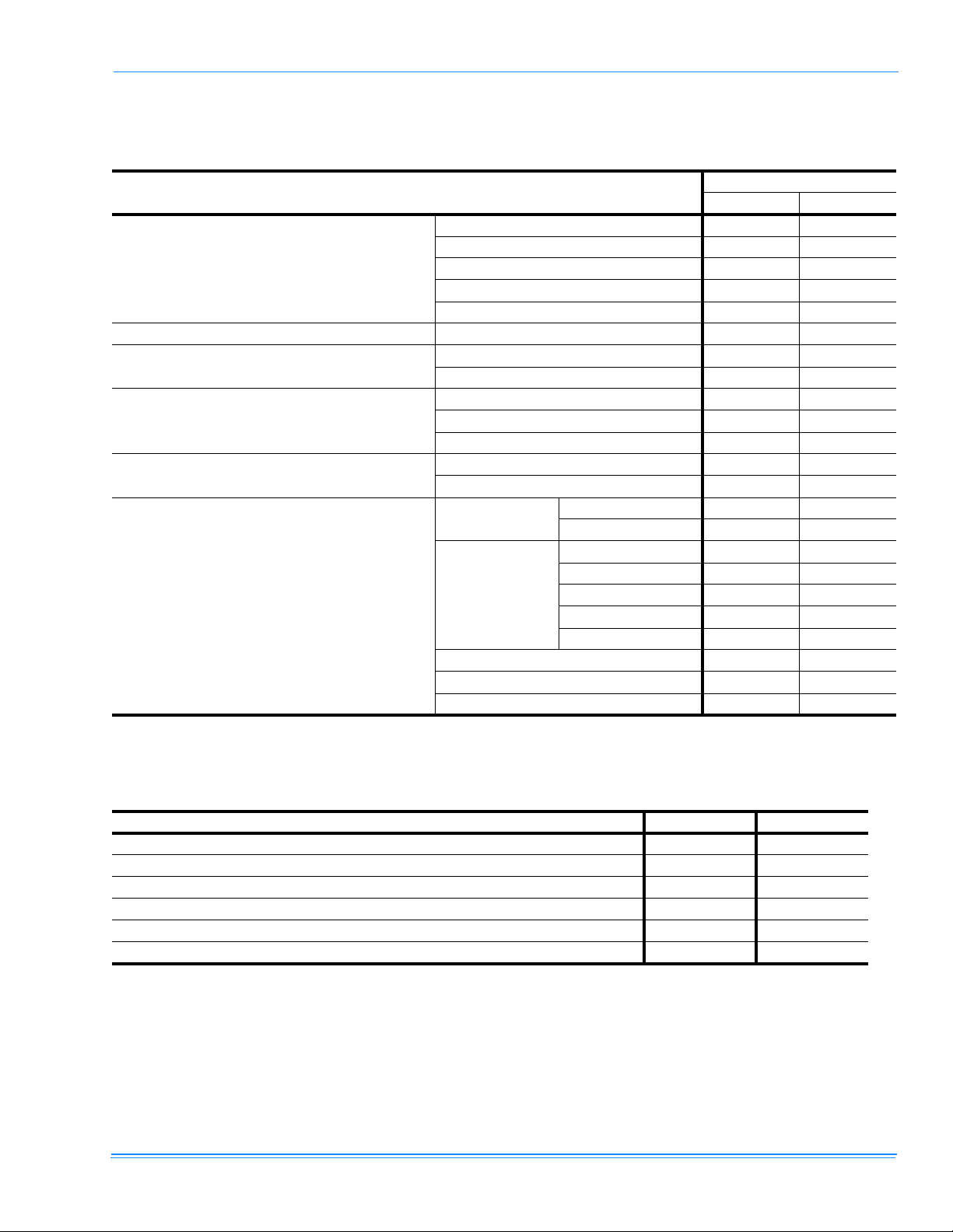
SUSPENSION
CHANNEL
035-18200-000-B-1102
HANGER RODS
(FIELD SUPPLIED)
C
55"
5"
A
3
1-1/2
SECTION
BLOWER
SECTION
COIL
B
ELECTRIC HEATER
ACCESSORY (40 Lb.)
58-11/16"
D
D
SUPPLY AIR PLENUM
ACCESSORY (100 Lb.)
FIGURE 2: UNIT SUSPENSION MOUNTING FHP180 (HORIZONTAL APPLICATIONS)
TABLE 3: FHP180 UNIT SUSPENSION WEIGHTS (LBS)
SUSP'N. POINT W/ 3 HP MOTOR W/ HEATER ACCESS W/ PLENUM ACCE SS
A95 95 85 85
B 120 120 100 100
C 95 115 165 185
D 115 140 185 205
Total Wt. 425 470 535 575
W/ HEATER & PLE NUM
ACCESS
6 UnitaryProductsGroup
 Loading...