

Luxaire AL6B030F3, AL6B048F3, AL6B036F3, AL6B042F3, AL6B060F3 Technical Manual
...
TECHNICAL GUIDE
ACCLIMATE
TM
SPLIT-SYSTEM AIR CONDITIONERS
16 SEER – R-410A
MODELS:
AL6B024 THRU 060
(2 THRU 5 NOMINAL TONS)
Due to continuous product improvement,
specifications are subject to change without notice.
Visit us on the web at
www.upgnet.com and www.luxaire.com
Additional rating information can be found at
www.ahridirectory.org
WARRANTY
Standard 5-year limited parts warranty.
10-year limited compressor warranty.
Premium System Warranty - Limited lifetime compressor
when matched with an approved Johnson Controls Unitary
Products premium furnace and coil or premium air handler.
Extended 10-year limited parts warranty when product is
registered online within 90 days of purchase for replacement or closing for new home construction.
LISTED
FOR DISTRIBUTION USE ONLY - NOT TO BE USED AT POINT OF RETAIL SALE
567177-LTG-D-1211
DESCRIPTION
The 16 SEER Series unit is the outdoor part of a versatile climate system. It is designed with a matching indoor coil component from Johnson Controls Unitary Products. Available for
typical applications, this climate system is supported with
accessories and documents to serve specific functions.
FEATURES
• Superior Coil Protection – A decorative, stamped metal coil
guard completely protects coil from debris and other large
damaging material.
• Isolated Compressor Compartment – A molded composite
bulkhead isolates the compressor from the rest of the unit,
reducing sound and vibration.
• Protected Compressors – Each compressor is protected
against abnormal pressures by an internal pressure relief
valve and factory installed high and low pressure controls.
Additional protection against moisture and debri s is provided
by factory installed liquid line filter driers.
• Environmentally Friendly Refrigerant – Next generation
refrigerant R-410A delivers environmentally friendly performance with zero ozone depletion.
• Durable Finish – Automotive quality finish provides the ultimate protection from harmful U.V. rays and rust creep,
ensuring long-lasting, high quality appearance. A powderpaint topcoat is applied over a baked-on primer, using a galvanized, zinc coated steel base material. The result is a finish that has been proven in testing to provide 33% greater
durability than conventional powder-coat finishes.
• Lower Installed Cost – Designed to provide enhanced
installability by featuring a slide-down control compartment
and angled service valves to reduce overall installation time
and cost.
• Low Operating Sound Levels – A fan design boasting technology adapted from aeronautic and defense engineering
provides for whisper quiet operation by allowing airflow to
flow smoothly and efficiently across the fan tips.
• Filter-Drier – A factory installed, solid core liquid line filterdrier filters harmful debris and moisture from the system.
• Easy Service Access – A full end, full service, access panel
with handle makes for easy entry to internal components.
• Composite Base - Strong and durable composite base pan
resists rust and corrosion while it helps reduce vibrations and
noise.
TM
• SilentDrive
wing fan, composite base pan, isolated compressor compartment, and single-stage compressor to reduce overall sound
to a mere whisper.
• Low RPM fan motor - Helps to reduce airflow noise.
• Communications Capable – Requiring only a simple 4-wire
installation, the communicating capability enables the use of
the Touch Screen Communicating Control, allowing real time
visibility of system operation and the use of diagnostic features, while still maintaining the ability to function with a traditional thermostat.
• Agency Listed - U.L. and C.U.L. listed - approved for outdoor application. The unit is certified in accordance with the
Unitary Small Equipment certification program, which is
based on AHRI Standard 210/240.
System - Features combination of swept-

567177-LTG-D-1211
VAPOR
LIQUID
2-3/8
3-1/8
6-1/2
C
A
B
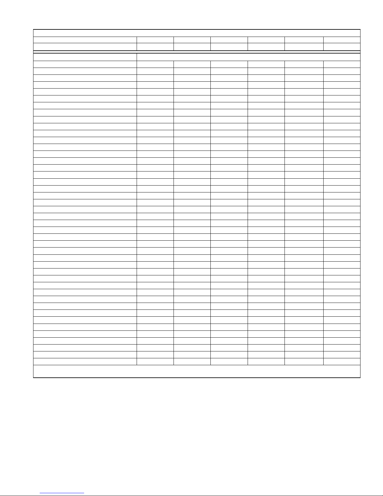
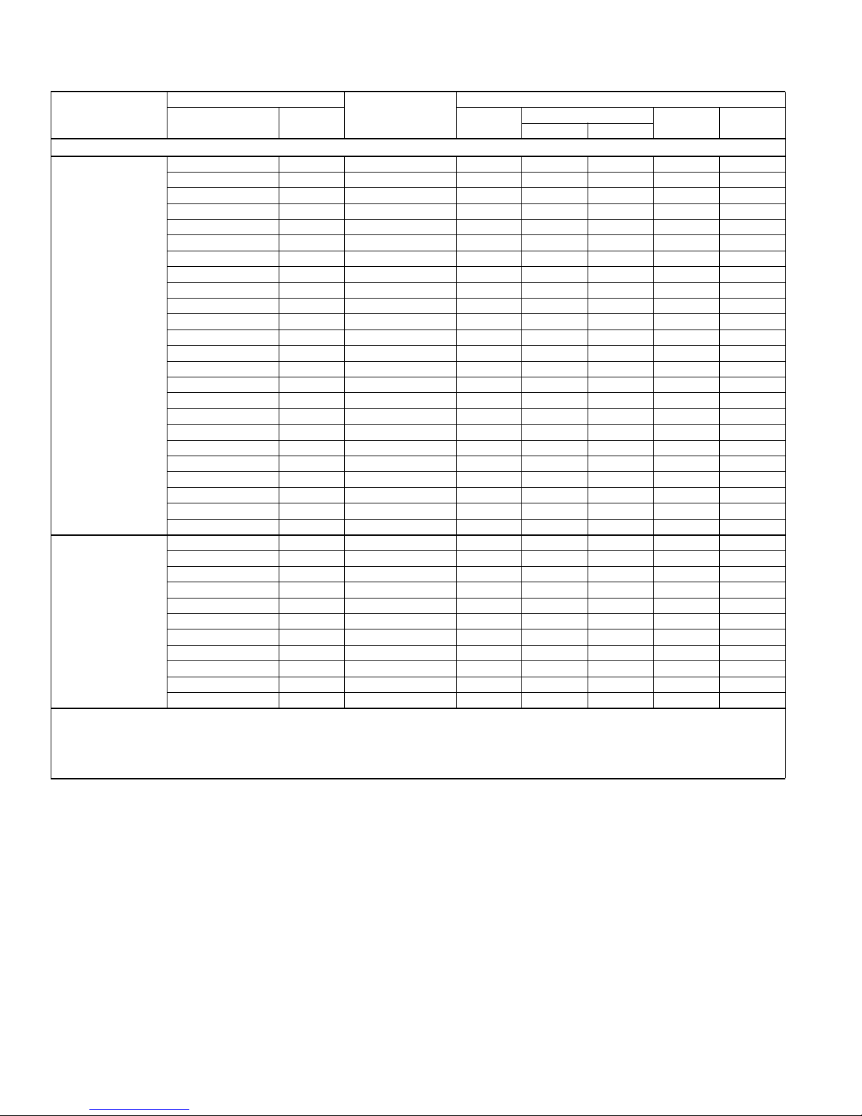
PHYSICAL AND ELECTRICAL DATA
MODEL AL6B024F3(C) AL6B030F3(C) AL6B036F3(C) AL6B042F3(C) AL6B048F3(C) AL6B060F3(C)
Unit Supply Voltage 208-230V, 1 60Hz
Normal Voltage Range
1
Minimum Circuit Ampacity 17.3 18.1 22.9 23.7 27.7 29.5
Max. Overcurrent Device Amps
Min. Overcurrent Device Amps
2
3
30 30 40 40 45 50
20 20 25 25 30 35
Multi-Stage Compressor No No No No No No
Compressor Type Scroll Scroll Scroll Scroll Scroll Scroll
Compressor Amps
Rated Load 13.4 14.1 17.3 17.9 21.1 21.4
Locked Rotor 58.3 73.0 96.7 112 106 135
Crankcase Heater No No No No No No
Factory External Discharge Muffler No No No No No No
Factory External Check Valve No No No No No No
HS Kit Required with TXV
4
No No No No No No
Fan Motor Amps Rated Load 0.5 0.5 1.3 1.3 1.3 2.8
Fan Diameter Inches 22 22 22 22 24 24
Rated HP 1/15 1/15 1/4 1/4 1/4 1/3
Fan Motor
Nominal RPM 850 850 850 850 850 917
Nominal CFM 2020 2045 3240 3300 3800 3900
Face Area Sq. Ft. 14.10 13.97 16.12 19.34 22.82 22.82
Coil
Rows Deep 1 1 1 1 1 1
Fins / Inch 23 23 23 23 23 23
Liquid Line Set OD (Field Installed) 3/8 3/8 3/8 3/8 3/8 3/8
Vapor Line Set OD (Field Installed) 3/4 3/4 3/4 7/8 7/8 1-1/8
Unit Charge (Lbs. - Oz.)
5
3 - 12 4 - 6 5 - 0 6 - 4 6 - 5 6 -14
Charge Per Foot, Oz. 0.62 0.62 0.62 0.67 0.67 0.75
Operating Weight Lbs. 159 166 192 209 225 235
1. Rated in accordance with ANSI/AHRI Standard 110-2002, utilization range “A”.
2. Dual element fuses or HACR circuit breaker. Maximum allowable overcurrent protection.
3. Dual element fuses or HACR circuit breaker. Minimum recommended overcurrent protection.
4. See Hard Start Kit Accessory Installation Manual for Hard Start Kit part number for each model.
5. The Unit Charge is correct for the outdoor unit, matched indoor coil, and 15 feet of refrigerant tubing. For tubing lengths other than 15 feet,
add or subtract the amount of refrigerant, using the difference in length multiplied by the per foot value.
187 to 252
All dimensions are in inches. They are subject to change without notice. Certified dimensions will be provided upon request.
2 Johnson Controls Unitary Products
Unit
Model
Dimensions
(Inches)
A B C Liquid Vapor
Refrigerant Connection
Service Valve Size
024 29-1/2 37 31
036 33-1/2 37 31
042 39-1/2 37 31
3/8”
048 39-1/2 42 34
060 39-1/2 42 34 7/8” *
* Expander fitting required for 1-1/8” line set.
3/4”030 29-1/2 37 31
7/8”
567177-LTG-D-1211
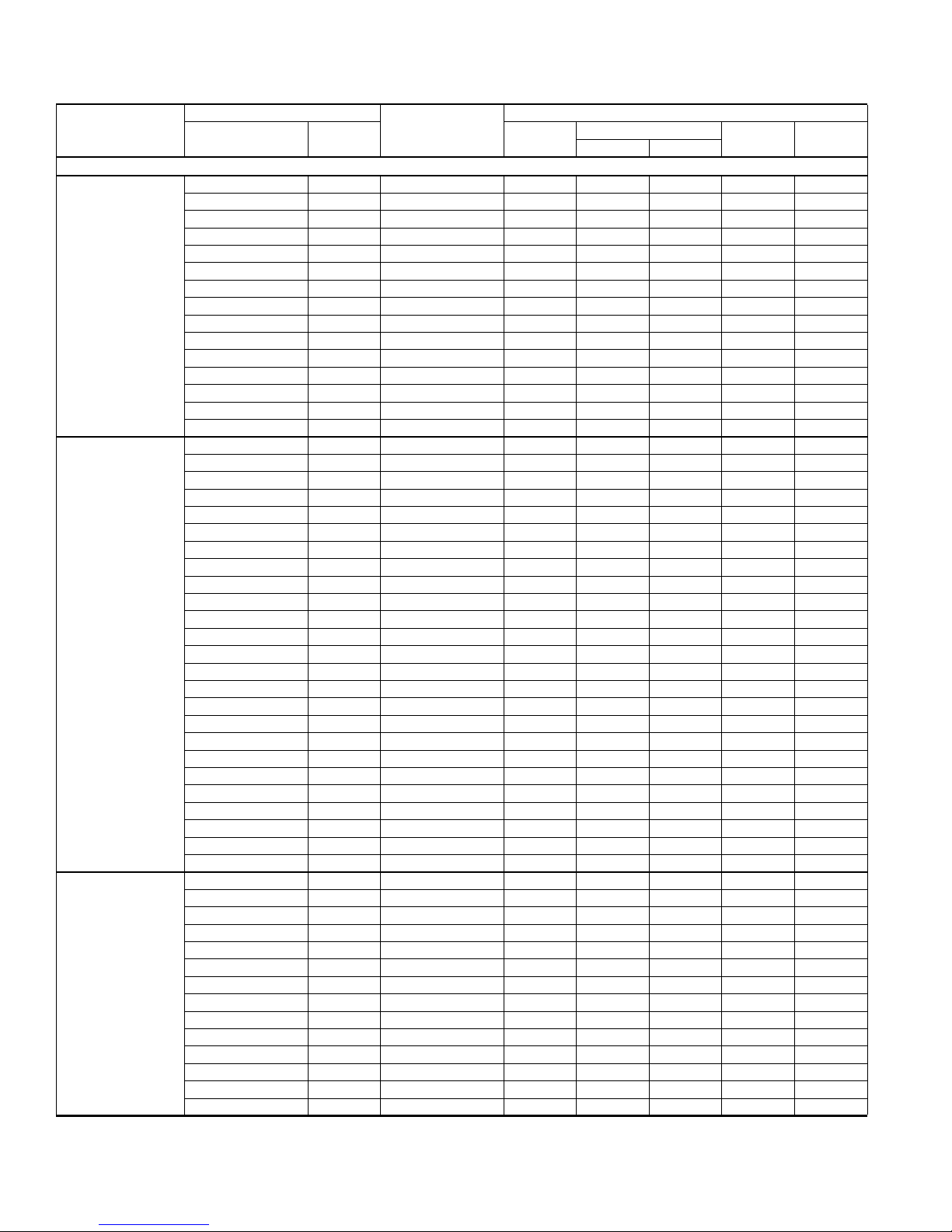
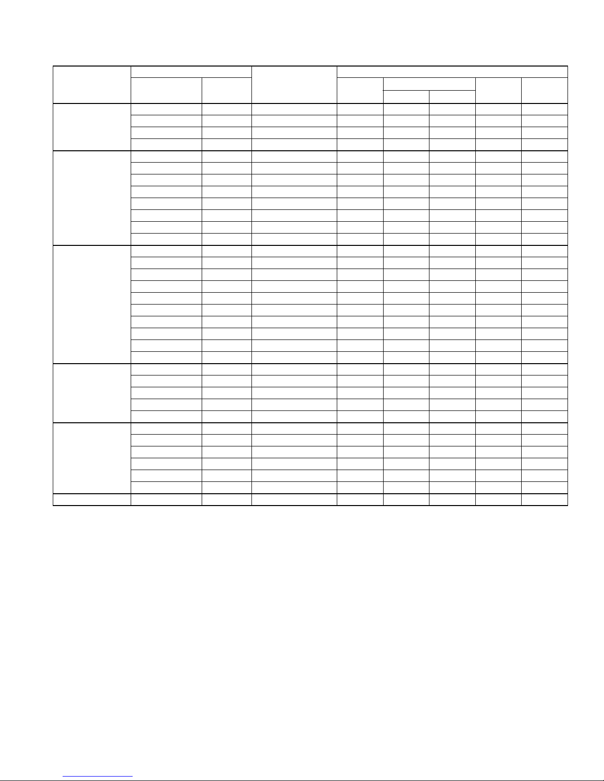
System Charge for Various Matched Systems
Outdoor Unit AL6B024F3(C) AL6B030F3(C) AL6B036F3(C) AL6B042F3(C) AL6B048F3(C) AL6B060F3(C)
Approved System Thermal Expansion Valve
Indoor Coil
AHE24B 9–––––
AHE30B 90––––
AHE36C 15 6 0 – – –
AHE42D –933– –
AHE48D – 13 7 7 4 –
AHE60D – – 12 12 9 4
AHP30 90––––
AHP36 –60–––
AHP42 ––0–––
AHP48 –––74–
AHP60 –––74–
AHR24B 9–––– –
AHR30B –0––– –
AHR36B –60–– –
AHR42C ––33––
AHR48D –––74–
AHR60D – – – 12 9 4
AV*36 1560–––
AV*48 ––774–
AV*60 –––740
AHX24 4–––––
AHX30 12 0 – – – –
AHX36 15 6 0 – – –
AHX42 ––33––
AHX48 ––774–
AHX60 – – 12 12 9 4
F6FP030 90––––
F6FP036 90––––
F6FP042 –933––
F6FP048 – 13 7 7 4 –
F6FP060 – – 12 12 9 4
F4FV060 ––774–
FC/MC/PC32 90––––
FC/MC/PC35 90––––
FC/MC/PC37 15 6 0 – – –
FC/MC/PC43 15 6 0 0 – –
FC/MC/PC48 –9330–
FC/MC/PC60 – 13 7 7 4 0
FC/MC62 – – 12 12 9 4
FC64 – – 18 18 15 11
HD48 ––330–
HD60 ––774–
UC48 –93–0–
UC60 – 13 7 7 4 –
Some of the combinations shown in the above System Charge table require Advanced Main Air Circulating Fan indoor product. For approved coil
only matches, please see the “COOLING CAPACITY - Upflow, Downflow & Horizontal Furnaces and Coils” table.
FOOTNOTES:
1. For applications requiring a TXV use S1-1TVM*** series kit.
2. Systems matched with furnace or air handlers not equipped with blower-off delays may require blower Time Delay Kit S1-2FD06700224.
3. PC coils cannot be used in downflow or horizontal applications. FC coils cannot be used in horizontal applications.
4. Refer to Cooling Performance Data tables for actual performance for specified system matches.
5. A TXV kit must be used with these coils to obtain system performance.
Note: If a TXV is factory installed on the coil, it must be replaced with the listed TXV.
PROCEDURES:
1. Unit factory charge listed on the unit nameplate includes refrigerant for the condenser, the smallest evaporator, and 15 feet of interconnecting
2. Verify the TXV and additional charge required for specific evaporator coil in the system using the above table.
3. Additional charge for the amount of interconnecting line tubing greater than 15 feet at the rate specified in Physical and Electrical Data Table.
4. For TXV matches requiring additional charge, the refrigerant needs to be weighed in for specific coil match and lineset length.
5. Permanently mark the unit nameplate with the total system charge. Total System Charge = Base Charge (as shipped) + charge adder for
2,3,4
line tubing.
evaporator + charge adder for line set.
Johnson Controls Unitary Products 3
1
4F1 4F1 4F1 4N1 4N1 4H1
TXV Kit5 - Additional Charge, Oz
567177-LTG-D-1211
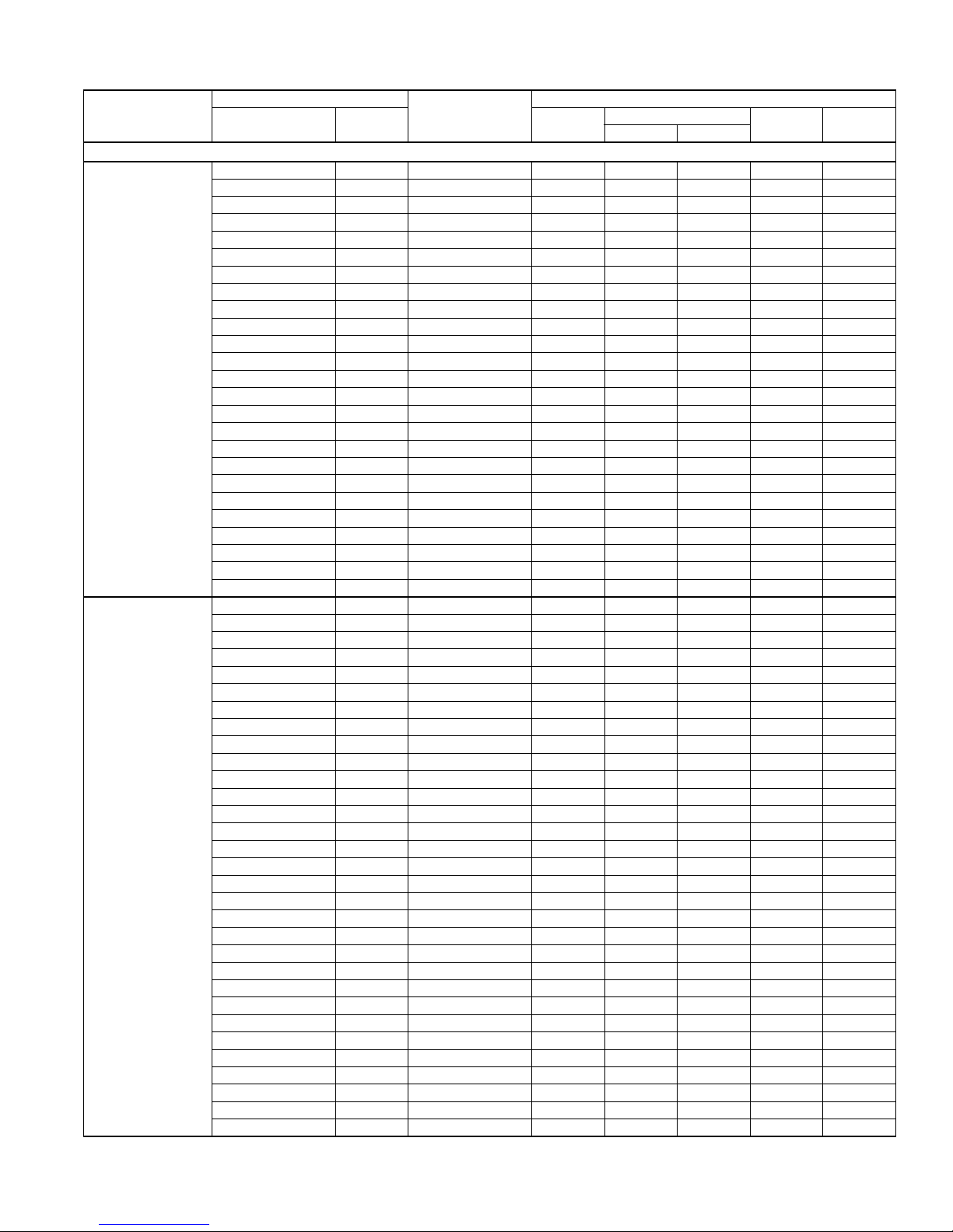
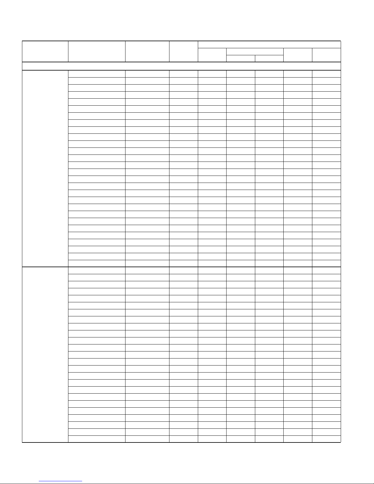
COOLING CAPACITY - With Air Handler Coils
UNIT
MODEL
AL6B024F3(C)
AL6B030F3(C)
AL6B036F3(C)
For Notes See Page 6.
AIR HANDLER
MODEL WIDTH
16 SEER AC WITH AIR HANDLERS
AHE24B 17 – 795 24.8 17.0 16.75 13.50
AHE30B 17 – 795 24.8 17.0 16.75 13.50
AHE36C 21 – 855 25.4 18.0 17.50 14.00
AHP30 17 – 800 23.6 17.0 14.50 12.00
AHR24B 17 – 740 23.6 16.6 15.00 12.75
AV*36 21 – 725 24.8 16.7 17.25 14.00
AHX24 17 – 800 24.6 16.9 16.75 13.50
AHX30 17 – 820 24.8 17.2 17.00 13.75
AHX36 21 – 820 25.0 17.3 16.50 13.25
F6FP030 17 – 850 24.8 17.2 16.50 13.25
F6FP036 21 – 855 25.0 17.3 16.75 13.50
MV12B 17 FC/MC35B 800 24.8 17.1 17.00 13.75
MV12B 17 FC/MC43B 800 25.0 17.2 17.00 13.75
MX12B 17 FC/MC35B 815 25.0 17.0 17.50 14.00
MX12B 17 FC/MC43B 735 24.8 16.8 17.50 14.00
AHE30B 17 – 985 30.0 20.6 15.75 12.75
AHE36C 21 – 1000 30.8 21.2 16.50 13.50
AHE42D 21 – 1000 31.2 21.6 17.00 13.75
AHE48D 24 – 1000 30.8 21.4 16.75 13.75
AHP30 17 – 1000 29.6 20.6 14.00 12.00
AHP36 21 – 1000 30.0 21.0 14.25 12.25
AHR30B 17 – 1115 30.0 21.6 14.00 12.00
AHR36B 21 – 1060 30.4 21.6 14.25 12.25
AV*36 21 – 960 30.6 21.0 16.25 13.50
AHX30 17 – 1025 29.8 20.7 15.25 12.75
AHX36 21 – 1005 30.8 21.4 16.75 13.50
F6FP030 17 – 1035 30.0 20.6 15.25 12.50
F6FP036 21 – 980 29.4 20.1 15.50 12.75
F6FP042 24 – 1065 31.0 21.7 16.50 13.50
F6FP048 24 – 1105 31.0 21.4 16.50 13.00
MV12B 17 FC/MC35B 1010 29.8 20.5 15.75 13.00
MV16C 21 FC/MC35C 1070 30.2 21.3 16.00 13.00
MV12B 17 FC/MC43B 990 30.6 21.1 16.25 13.25
MV16C 21 FC/MC43C 1000 30.8 21.2 16.25 13.25
MV16C 21 FC/MC48C 1000 31.0 21.4 16.50 13.50
MX12B 17 FC/MC35B 1085 30.6 21.6 16.25 13.00
MX16C 21 FC/MC35C 1035 30.4 20.8 16.75 13.50
MX12B 17 FC/MC43B 1095 31.2 22.0 16.50 13.50
MX16C 21 FC/MC43C 970 30.8 21.2 17.00 13.75
MX16C 21 FC/MC48C 995 31.2 21.4 17.00 13.75
AHE36C 21 – 1190 35.8 26.6 16.00 13.00
AHE42D 21 – 1180 36.2 26.8 16.25 13.50
AHE48D 24 – 1195 36.0 26.6 16.25 13.50
AHE60D 24 – 1190 36.4 27.0 16.50 13.75
AHP36 21 – 1200 35.0 26.0 14.00 12.25
AHP42 21 – 1255 35.0 26.0 14.00 12.25
AHR36B 21 – 1245 34.8 25.8 13.75 12.00
AHR42C 21 – 1230 35.6 26.6 14.25 12.50
AV*36 21 – 1190 35.8 26.8 16.00 13.00
AV*48 24 – 1220 36.4 27.4 16.50 13.50
AHX36 21 – 1225 36.0 26.8 16.00 13.25
AHX42 21 – 1190 36.4 27.2 16.50 13.75
AHX48 24 – 1255 36.6 28.0 16.50 13.50
AHX60 24 – 1300 36.8 28.2 16.50 13.50
COIL MODEL
1
RATED
CFM
TOTAL SENS.
COOLING
NET MBH
SEER EER
4 Johnson Controls Unitary Products
567177-LTG-D-1211
COOLING CAPACITY - With Air Handler Coils (Continued)
UNIT
MODEL
AL6B036F3(C)
AL6B042F3(C)
For Notes See Page 6.
AIR HANDLER
MODEL WIDTH
F6FP042 24 – 1290 36.6 27.6 16.00 13.25
F6FP048 24 – 1125 35.4 26.2 16.00 13.25
F6FP060 24 – 1240 36.6 27.6 16.25 13.50
F4FV060 24 – 1200 36.0 27.0 16.25 13.25
MV12B 17 FC/MC43B 1225 36.0 26.6 15.75 13.00
MV16C 21 FC/MC43C 1190 36.0 26.6 16.00 13.25
MV12D 24 FC/MC48D 1160 36.6 26.8 16.50 13.75
MV16C 21 FC/MC48C 1200 36.2 26.8 16.25 13.25
MV20D 24 FC/MC48D 1300 36.8 28.0 16.25 13.50
MV12D 24 FC/MC60D 1135 36.0 26.4 16.00 13.25
MV20D 24 FC/MC60D 1300 36.4 27.4 16.25 13.50
MV12D 24 FC/MC62D 1155 36.6 27.2 16.75 13.75
MV20D 24 FC/MC62D 1300 36.8 28.0 16.50 13.50
MV12D 24 FC64D 1155 37.0 27.8 17.00 14.00
MV20D 24 FC64D 1300 37.2 28.8 16.75 14.00
MX12B 17 FC/MC43B 1220 35.8 26.6 15.50 12.75
MX16C 21 FC/MC43C 1140 35.8 26.2 16.25 13.50
MX12D 24 FC/MC48D 1225 36.4 26.6 16.00 13.25
MX16C 21 FC/MC48C 1150 36.6 26.8 16.50 13.75
MX12D 24 FC/MC60D 1275 36.6 27.4 16.25 13.50
MX20D 24 FC/MC60D 1295 36.8 27.8 16.75 13.75
MX12D 24 FC/MC62D 1270 36.8 27.8 16.75 13.75
MX20D 24 FC/MC62D 1260 36.8 27.8 16.75 13.75
MX12D 24 FC64D 1270 37.8 29.2 17.25 14.25
MX20D 24 FC64D 1260 37.8 29.0 17.25 14.25
AHE42D 21 – 1385 40.5 30.4 15.50 13.00
AHE48D 24 – 1385 42.0 31.2 15.75 13.25
AHE60D 24 – 1390 42.5 32.0 16.25 13.75
AHP48 24 – 1400 41.5 31.0 14.50 12.25
AHP60 24 – 1400 42.0 31.4 15.50 13.00
AHR42C 21 – 1485 40.0 30.2 13.75 11.75
AHR48D 24 – 1320 41.0 29.8 14.00 11.75
AHR60D 24 – 1350 41.5 30.8 14.50 12.25
AV*48 24 – 1385 42.0 31.0 16.00 13.25
AV*60 24 – 1360 42.0 31.0 16.00 13.25
AHX42 21 – 1395 40.5 30.2 15.75 13.25
AHX48 24 – 1445 42.5 32.2 16.00 13.50
AHX60 24 – 1440 42.5 32.0 16.00 13.25
F6FP042 24 – 1455 40.5 30.4 15.25 13.00
F6FP048 24 – 1380 41.5 30.4 15.25 13.00
F6FP060 24 – 1475 43.0 32.4 15.75 13.25
F4FV060 24 – 1350 41.0 30.2 15.50 13.00
MV16C 21 FC/MC43C 1380 40.0 29.6 15.00 12.75
MV16C 21 FC/MC48C 1400 40.5 29.6 15.25 13.00
MV20D 24 FC/MC48D 1470 41.0 31.2 15.75 13.25
MV16C 21 FC/MC60C 1400 42.0 30.8 15.50 13.00
MV20D 24 FC/MC60D 1400 42.0 30.8 15.75 13.25
MV20D 24 FC/MC62D 1450 42.5 32.0 16.00 13.25
MV20D 24 FC64D 1400 43.0 32.4 16.50 13.75
MX16C 21 FC/MC43C 1365 40.0 29.8 15.00 12.75
MX16C 21 FC/MC48C 1390 40.5 29.8 15.75 13.50
MX20D 24 FC/MC48D 1415 40.5 30.6 15.75 13.25
MX16C 21 FC/MC60C 1420 42.5 31.6 16.00 13.25
MX20D 24 FC/MC60D 1470 43.0 32.4 16.25 13.50
MX20D 24 FC/MC62D 1470 43.5 32.8 16.25 13.75
MX20D 24 FC64D 1470 44.5 34.2 16.75 14.00
COIL MODEL
16 SEER AC WITH AIR HANDLERS
1
RATED
CFM
TOTAL SENS.
Johnson Controls Unitary Products 5
COOLING
NET MBH
SEER EER
567177-LTG-D-1211
COOLING CAPACITY - With Air Handler Coils (Continued)
UNIT
MODEL
AIR HANDLER
MODEL WIDTH
COIL MODEL
1
RATED
CFM
TOTAL SENS.
16 SEER AC WITH AIR HANDLERS
AHE48D 24 – 1600 45.0 33.2 15.00 12.50
AHE60D 24 – 1565 45.5 33.8 15.50 13.00
AHP48 24 – 1600 45.0 32.2 13.75 12.00
AHP60 24 – 1600 46.0 32.8 14.50 12.50
AHR48D 24 – 1610 45.5 32.6 13.75 12.00
AHR60D 24 – 1620 45.5 32.8 14.00 12.25
AHX48 24 – 1660 46.0 34.4 15.25 12.75
AHX60 24 – 1570 46.0 33.8 15.50 13.00
AV*48 24 – 1625 45.5 33.6 15.25 12.50
AV*60 24 – 1560 45.5 33.8 15.50 12.75
F6FP048 24 – 1625 45.5 33.6 15.00 12.50
AL6B048F3(C)
F6FP060 24 – 1570 46.0 33.8 15.50 13.00
F4FV060 24 – 1600 45.0 33.6 15.00 12.50
MV16C 21 FC/MC48C 1625 45.0 33.0 14.50 12.50
MV20D 24 FC/MC48D 1620 45.0 33.2 14.75 12.75
MV16C 21 FC/PC60C 1600 44.5 32.8 14.00 11.75
MV20D 24 FC/MC60D 1600 45.0 33.2 15.00 12.50
MV20D 24 FC/MC62D 1630 45.5 33.8 15.50 12.75
MV20D 24 FC64D 1630 47.0 35.8 16.00 13.25
MX16C 21 FC/MC48C 1685 45.0 34.0 14.50 12.50
MX20D 24 FC/MC48D 1525 45.0 33.2 14.75 13.00
MX16C 21 FC/PC60C 1630 45.0 33.0 14.50 13.00
MX20D 24 FC/MC62D 1605 46.0 34.0 15.75 13.25
MX20D 24 FC64D 1605 47.0 36.0 16.50 13.50
AHE60D 24 – 1835 53.5 38.0 15.25 13.00
AHR60D 24 – 1870 52.0 36.2 13.75 12.00
AHX60 24 – 1865 53.5 38.5 15.40 13.00
AV*60 24 – 1730 52.5 36.4 15.25 12.75
F6FP060 24 – 1865 53.5 38.5 15.40 13.00
AL6B060F3(C)
MV20D 24 FC/MC60D 1845 53.0 37.3 15.00 12.75
MV20D 24 FC/MC62D 1855 53.5 38.0 15.00 12.75
MV20D 24 FC64D 1705 54.5 39.0 16.00 13.50
MX20D 24 FC/MC60D 1780 53.0 37.5 15.50 13.00
MX20D 24 FC/MC62D 1795 54.0 38.5 15.75 13.25
MX20D 24 FC64D 1795 55.0 40.0 16.25 13.50
Rated in accordance with DOE test procedures (Federal Register 12-27-79 and 3-18-88) and AHRI Standard 210/240.
Cooling MBH based on 8°F entering air temperature, 50% RH (Relative Humidity), and rated air flow.
EER (Energy Efficiency Ratio) is the total cooling output in BTUs at 95 °F outdoor ambient divided by the total electric power in watt-hours at those conditions.
SEER (Seasonal Energy Efficiency Ratio) is the total cooling output in BTUs during a normal annual usage period for cooling divided by the total electric power
input in watt-hours during the same period.
1. MC coils available with a factory installed horizontal drain pan. See price pages for specific model number.
— = Not applicable.
MA Modular Air Handlers use Coil Only Ratings.
COOLING
NET MBH
SEER EER
6 Johnson Controls Unitary Products
567177-LTG-D-1211
COOLING CAPACITY - Upflow, Downflow & Horizontal Furnaces and Coils (Coil Only Ratings)
FURNACE
UNIT MODEL
AL6B024F3(C)
AL6B030F3(C)
AL6B036F3(C)
AL6B042F3(C)
AL6B048F3(C)
AL6B060F3(C) 1500 - 1900 24 FC64 1800 53.5 37.4 14.50 12.50
1. Requires a S1-2FD06700224 Blower Time Delay unless a standard furnace is equipped with one.
2. TXV = Use S1-1TVM series kit.
MA Modular Air Handlers use Coil Only Ratings.
PSC furnaces, such as the TG8S, TGLS, and TG9S, use Coil Only Ratings.
CFM RANGE
(MIN.-MAX.)
600 - 1000 14 FC/MC/PC32 800 23.6 17.0 14.50 12.25
600 - 1000 17,21 FC/MC/PC35 800 23.6 17.0 14.50 12.25
600 - 1000 14 FC/MC/PC37 800 24.0 17.3 14.50 12.25
600 - 1000 17,21 FC/MC/PC43 800 24.0 17.3 14.50 12.25
800 - 1200 14 FC/MC/PC32 1000 29.6 20.6 14.00 12.00
800 - 1200 17,21 FC/MC/PC35 1000 29.6 20.6 14.00 12.00
800 - 1200 14 FC/MC/PC37 1000 30.0 21.0 14.25 12.25
800 - 1200 17,21 FC/MC/PC43 1000 30.0 21.0 14.25 12.25
800 - 1200 21,24 FC/MC/PC48 1000 30.0 21.4 14.25 12.25
800 - 1200 21,24 FC/MC/PC60 1000 30.0 21.2 14.25 12.25
800 - 1200 21,24 UC48 1000 28.6 20.0 13.75 11.75
800 - 1200 21,24 UC60 1000 28.8 19.9 13.75 11.75
1000 - 1400 14 FC/MC/PC37 1200 35.0 26.0 14.00 12.25
1000 - 1400 17,21 FC/MC/PC43 1200 35.0 26.0 14.00 12.25
1000 - 1400 21,24 FC/MC/PC48 1200 35.0 26.0 14.00 12.25
1000 - 1400 21,24 FC/MC/PC60 1200 35.0 26.0 14.00 12.25
1000 - 1400 24 FC/MC62 1200 35.4 26.0 14.00 12.25
1000 - 1400 24 FC64 1200 36.4 27.4 14.50 12.50
1000 - 1400 – HD48 1200 35.0 25.8 14.00 12.25
1000 - 1400 – HD60 1200 35.4 26.0 14.00 12.25
1000 - 1400 21,24 UC48 1200 34.6 25.8 13.75 12.00
1000 - 1400 21,24 UC60 1200 34.6 25.4 13.75 12.00
1200 - 1600 21,24 FC/MC/PC60 1400 41.5 30.2 14.25 12.00
1200 - 1600 24 FC/MC62 1400 41.5 30.2 14.50 12.25
1200 - 1600 24 FC64 1400 42.5 31.8 15.00 12.50
1200 - 1600 – HD60 1400 42.0 30.8 14.25 12.25
1200 - 1600 21,24 UC60 1400 40.5 29.6 13.75 11.75
1400 - 1800 21,24 FC/MC/PC48 1600 45.0 32.2 13.75 12.00
1400 - 1800 21,24 FC/MC/PC60 1600 45.0 32.2 13.75 12.00
1400 - 1800 24 FC/MC62 1600 45.5 32.8 13.75 12.00
1400 - 1800 24 FC64 1600 47.0 34.2 14.25 12.50
1400 - 1800 – HD48 1600 45.0 32.2 13.75 12.00
1400 - 1800 – HD60 1600 46.0 32.8 14.00 12.25
WIDTH
COIL
MODEL
RATED
CFM
TOTAL SENS.
COOLING
NET MBH
SEER
1,2
EER
Johnson Controls Unitary Products 7
567177-LTG-D-1211
COOLING CAP ACITY - With High Efficiency Motor Furnaces
UNIT
MODEL
AL6B024F3(C)
AL6B030F3(C)
For Notes See Page 14.
FURNACE
MODEL
16 SEER AC WITH HIGH EFFICIENCY MOTOR FURNACES
T*(8,L)X*A12 FC/MC/PC32A 14 800 24.8 17.0 17.25 14.00
T*(8,L)X*B12 FC/MC/PC35B 17 850 25.2 17.7 17.50 14.25
T*9X*B12 FC/MC/PC35B 17 785 24.8 17.0 17.25 14.00
T*(8,L)X*C16 FC/MC/PC35C 21 865 25.2 17.8 17.50 14.25
T*(8,L)X*C20 FC/MC/PC35C 21 885 25.2 18.0 17.00 14.00
T*9X*C16 FC/MC/PC35C 21 765 24.8 17.0 17.25 14.00
T*9X*C20 FC/MC/PC35C 21 825 24.8 17.0 17.00 13.75
T*(8,L)X*A12 FC/MC/PC37A 14 840 25.4 17.9 17.75 14.25
T*(8,L)X*B12 FC/MC/PC43B 17 865 25.6 18.1 17.75 14.25
T*9X*B12 FC/MC/PC43B 17 800 25.2 17.3 17.50 14.00
T*(8,L)X*C16 FC/MC/PC43C 21 855 25.4 18.1 17.75 14.25
T*(8,L)X*C20 FC/MC/PC43C 21 815 25.0 17.2 17.25 14.00
T*9X*C16 FC/MC/PC43C 21 785 25.2 17.3 17.50 14.00
T*9X*C20 FC/MC/PC43C 21 790 25.0 17.2 17.25 14.00
(L*LC/T*8V/T*LV)*A12 FC/MC/PC32A 14 755 24.4 16.6 16.50 13.50
(L*LC/T*8V/T*LV)*B12 FC/MC/PC35B 17 785 24.8 16.9 16.75 13.75
(L*9C/T*9V)*B12 FC/MC/PC35B 17 815 24.6 16.9 16.50 13.25
(L*LC/T*8V/T*LV)*C16 FC/MC/PC35C 21 775 24.8 17.0 17.00 13.75
(L*LC/T*8V/T*LV)*C20 FC/MC/PC35C 21 755 24.6 16.7 17.00 13.75
(L*9C/T*9V)*C16 FC/MC/PC35C 21 900 25.2 18.0 16.75 13.75
(L*9C/T*9V)*C20 FC/MC/PC35C 21 755 24.6 16.7 16.75 13.75
(L*LC/T*8V/T*LV)*A12 FC/MC/PC37A 14 765 25.0 17.2 16.75 13.50
(L*LC/T*8V/T*LV)*B12 FC/MC/PC43B 17 790 25.0 17.2 17.00 13.75
(L*9C/T*9V)*B12 FC/MC/PC43B 17 800 25.0 17.1 16.75 13.50
(L*LC/T*8V/T*LV)*C16 FC/MC/PC43C 21 770 25.0 17.2 17.25 14.00
(L*LC/T*8V/T*LV)*C20 FC/MC/PC43C 21 740 24.8 16.8 17.25 13.75
(L*9C/T*9V)*C16 FC/MC/PC43C 21 810 25.0 17.2 17.00 13.75
(L*9C/T*9V)*C20 FC/MC/PC43C 21 890 25.6 18.3 17.00 14.00
T*(8,L)X*A12 FC/MC/PC32A 14 970 29.6 20.3 15.00 12.50
T*(8,L)X*B12 FC/MC/PC35B 17 1120 30.2 21.5 15.50 13.00
T*9X*B12 FC/MC/PC35B 17 1085 30.2 21.3 15.50 13.00
T*(8,L)X*C16 FC/MC/PC35C 21 1105 30.4 21.5 15.75 13.00
T*(8,L)X*C20 FC/MC/PC35C 21 850 29.0 19.3 15.50 13.00
T*9X*C16 FC/MC/PC35C 21 1075 30.2 21.1 15.50 13.00
T*9X*C20 FC/MC/PC35C 21 835 29.0 19.3 15.75 13.00
T*(8,L)X*A12 FC/MC/PC37A 14 1105 31.2 22.2 16.25 13.25
T*(8,L)X*B12 FC/MC/PC43B 17 1125 31.2 22.4 16.25 13.25
T*9X*B12 FC/MC/PC43B 17 1095 31.2 22.0 16.50 13.25
T*(8,L)X*C16 FC/MC/PC43C 21 955 31.0 21.2 16.75 13.50
T*(8,L)X*C20 FC/MC/PC43C 21 870 30.2 20.2 16.50 13.50
T*9X*C16 FC/MC/PC43C 21 1055 31.0 21.8 16.50 13.25
T*9X*C20 FC/MC/PC43C 21 720 28.8 18.6 16.00 13.00
T*(8,L)X*C16 FC/MC/PC48C 21 970 31.2 21.4 17.00 13.75
T*(8,L)X*C20 FC/MC/PC48C 21 890 30.6 20.8 16.75 13.75
T*9X*C16 FC/MC/PC48C 21 1075 31.4 22.2 16.75 13.50
T*9X*C20 FC/MC/PC48C 21 745 29.4 19.0 16.25 13.25
T*9X*D20 FC/MC/PC48D 24 780 29.6 19.5 16.50 13.25
T*(8,L)X*C16 FC/PC60C 21 1115 31.2 22.1 17.00 13.50
T*(8,L)X*C20 FC/PC60C 21 895 30.6 20.7 17.00 13.75
T*9X*C16 FC/PC60C 21 1080 31.4 22.1 16.75 13.50
T*9X*C20 FC/PC60C 21 905 29.4 20.1 16.25 13.50
T*9X*D20 FC/MC/PC60D 24 945 29.6 20.3 16.50 13.50
T*(8,L)X*C16 UC48C 21 970 28.8 19.6 16.00 13.00
COIL
MODEL
1
WIDTH
RATED
CFM
COOLING
NET MBH
TOTAL SENS.
2
SEER EER
8 Johnson Controls Unitary Products
 Loading...