

Page 1
Page 1
©® copyright luxair UK Ltd 2014
To avoid the risk of accidents
or damage to this appliance It is
Essential to read these
Instructions before it is installed
and used for the first time.
Operating & Installation
Instructions: All Models
Page 2

Page 2
Caring for the enviroment………………………………….03
Warning and Safety………………………………………04-06
Ducting Requirments………………………………………07
Recirculated Hoods………………………………………...08
Checking Your Goods……………………………………..09
Installation of Wall Mounted Hoods STD Models………10-12
Fitting Charcoal Filters…………………………..............13-14
Installation of Wall Mounted Hoods CVD Models……. 15-16
Operating Instructions……………………………………..17
Installation of all Island Hoods…………………………..18-20
Changing the Bulbs………………………………………21-22
Changing Your light Fittings……………………………....23
Problem Solving……………………………………………24
Cleaning and Care………………………………………..25-26
Technical Specifications…………………………………...27
Warranty Form…………………………………………….28
Terms And Conditions……………………………………29-31
Contact Us…………………………………………………32
Contents:
Page 3
Page 3
Disposal Of the Packaging
Material
The transport and protective packing
has been selected from materials, which
are environmentally friendly for
disposal, and can normally be
recycled.
Packaging e.g. cling film, polystyrene
and plastic wrappings must be kept out
of the reach of babies and young
children. Danger of suffocation!
Dispose of or recycle all packaging
materials safely as soon as possible.
Ensure that electrical current is
switched off to the appliance until
after maintenance or repair work
has been carried out by a suitably
qualified engineer or electrician.
Domestic repairs or attempted
repairs will void the
warranty.
Disposal of your old appliance
Electrical and electronic appliances
often contain materials that, if
handled or disposed of incorrectly,
could be potentially hazardous to
human health and to the environment
They are, however, essential for the
correct functioning of your appliance.
Please do not therefore dispose of your
old appliance with your household
waste.
Please dispose of it at your local
community waste collection / recycling
center and ensure that it presents no
danger to children while being stored
for disposal.
It should be unplugged or disconnected
from the mains electricity supply by a
competent person. If connected by a
plug, the plug must be rendered
useless and the cable cut off directly
Behind the appliance to prevent
misuse. See the "Warning and Safety"
Caring for the environment
Page 4
Page 4
This appliance complies with all
relevant legal safety requirements.
Inappropriate use can, however,
lead to personal injury and damage
to property.
To avoid the risk of accidents and
damage to the appliance, please
read these instructions carefully
before using it for the first time. They
contain important information on the
safety, installation, use and
maintenance of the appliance. Keep
these instructions in a safe
Keep these instructions in a safe
familiar with the contents. Pass them
on to any future owner of the
appliance.
Correct Usage:
This appliance is intended for
domestic use only.
Luxair cannot be held liable for
damage caused by improper
installation or
incorrect use of the
appliance.
We Reserve the right to invalidate any
warranty supplied with this product
following incorrect istallation or
misuse of the appliance, or if used in a
commercial enviroment.
Important:
Before connecting the appliance to the
mains supply, make sure
that the connection details given
on the data plate correspond with the
on-site electricity supply; otherwise
the appliance could get damaged. The
appliance could get damaged Consult a
qualified electrician if in any doubt.
The electrical safety of this appliance
can only be guaranteed when continuity
is complete between the appliance and
an effective earthing
the appliance and an effective earthing
national safety regulations. It is most
important that this basic safety
requirement is present and regularly
tested, and where there is in any doubt,
the household wiring system should be
inspected by a qualified electrician.
The manufacturer cannot be held liable
for the consequences of an inadequate
earthing system (e.g. electric shock).
Installation, maintenance and
repair work may only be carried out
by a suitably qualified and competent
person in strict accordance with
national and local safety regulations.
Repairs and other work by unqualified
persons could be dangerous. The
manufacturer cannot be held liable for
unauthorized work.
Warning & Safety Instructions
Page 5

Page 5
Do not connect the appliance to the mains
electricity supply by an extension lead.
Extension leads do not guarantee the
required safety of the appliance (e.g. danger
of overheating).
In countries where there are areas
which may be subject to
infestation by cockroaches or other vermin,
pay particular attention to keeping
the appliance and its surroundings in
a clean condition at all times. Any damage
which may be caused by
cockroaches or other vermin will not be
covered by the guarantee.
Never use an open flame
beneath the cooker hood. To avoid the
danger of fire, do not flambé or grill over
an open flame under the cooker hood.
When switched on, the cooker hood could
draw flames into the filter. Fat particles
drawn into the cooker hood present a fire
hazard.
When using the cooker hood over a
gas hob, ensure that any burners in use
are always covered by a pan. The burner
should be switched off before taking a pan
off the hob, even for brief periods.
Regulate the flames so that they do not
extend beyond the base of the pan.
If flames are not covered by a pan
excessive heat can build up in the
cooker hood with the risk of damage to
the motor unit.
Always switch the cooker hood on when
a cooking zone is in use, otherwise
condensation may collect in the hood,
which could cause corrosion.
When cooking with oil or fat, chip
pans and deep fat fryers etc, do not
leave the pans unattended. Never leave
an open grill unattended when grilling,
Overheated oil and fat can ignite and
could set the cooker hood on fire.
Do not use the cooker hood without the
grease filters in place. This way you
will avoid the risk of grease and dirt
getting into the appliance and
hindering its smooth operation.
The grease filter should be
regularly cleaned. A saturated
filter is a fire hazard. See "Cleaning
and care”. For further information.
Do not use a steam-cleaner to
clean this appliance. Pressurised
steam could reach the electrical
components and cause a short circuit.
Never use spray cleaners directly
around the controls or buttons, this
could also cause damage to the
internal circuit board.
Safety with children:
This appliance is only intended for
use by adults who have read these
instructions it is not a toy! To avoid the
risk of injury, keep children well away,
and do not allow them to play with it or
use the controls.
Please be aware that on
appliances with halogen lighting, the
lamps will get very hot during use and
remain hot for some time after
switching off.
Warning & Safety Instructions
Page 6
Page 6
Warning & Safety Instructions
To safeguard against
burning, keep children well away from
the lamps at all times.
Packaging e.g. cling film,
polystyrene and plastic wrappings must
be kept out of the reach of babies and
young children. Danger of suffocation.
Dispose of or recycle all packaging
safely
as soon as possible.
Installation:
The distance between the top of
the cooker/hob and the bottom of the
cooker hood canopy must measure at
least
750mm
, unless a greater distance
is specified by Luxair.
If more than one appliance is fitted
beneath the cooker hood, and they have
different minimum safety distances
to the cooker hood, select the greater
distance.
Safety regulations prohibit the fitting of
a cooker hood over solid fuel stoves.
All ducting, pipe work and
fittings must be of non-flammable
material. These can be obtained from the
Luxair web site or from local builders'
merchants.
Note: All porducts MUST be fitted with
a 3amp fuse.
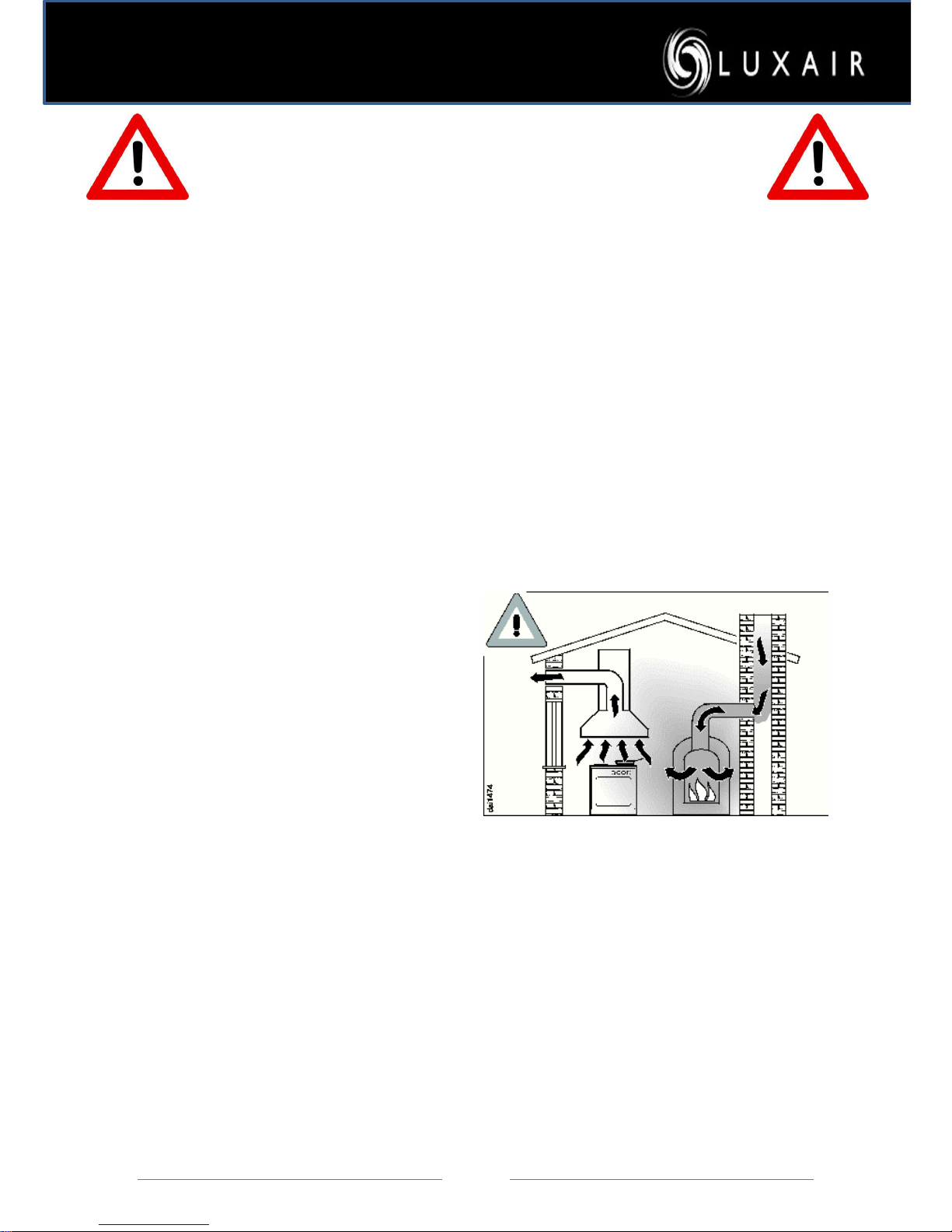
The appliance must not be
connected to a chimney or vent
flue, which is in use. Neither should it
be connected to ducting, which
ventilates rooms with fireplaces.
If exhaust air is to be extracted into a
chimney or ventilation duct no longer
used for other purposes, or using at the
same time as other heating appliances that
depend on the air from the room seek
advice.
.
Page 7
Page 7
Ducting Requirements
Please Take Note Of The Following:
Ducting kits are used to vent you’ re kitchen odors to the outside of the house, and we recommend
that only Luxair ducting kits are used with our products, this will also assure you that the
product’s warranty is not affected
All Luxair cooker hoods must be fitted with 125mm-150mm ducting. This
must not be reduced in any way for the entire length of its run, it must also
not exceed 3.5mtrs in length from the top of the motor housing connection
to the outside vent plate unless the motor size exceed 980m3/hr (applies to all wall mounted and
island models).
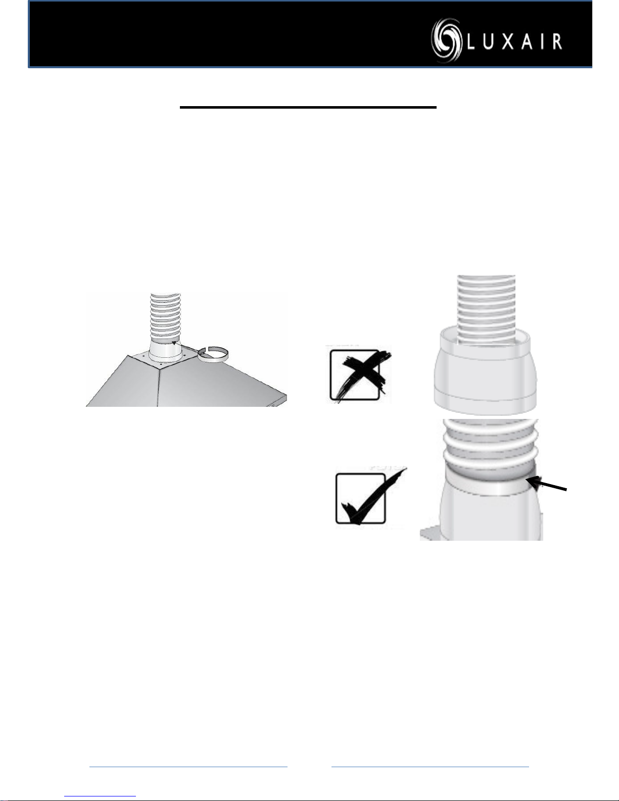
Ducting must be fitted to
the out-side of the
reducer collar and
secured with a zip
fastener, also the d ucting
must b e aluminium and
conform to fire
regulations.
Kits can be purchased
form Luxair’s web site.
The minimum height
setting measuring from
the underside of the
extractor, to the top of the
gas hob is 750mm
And 650mm on electric
hobs, please note that
when using a hob larger
than 60cm please set the
minimum height to 750mm
Warning:
Luxair will not cover the warranty
if you have installed the cooker
hood on either,
100mm ducting, or an old or
existing ducting used by a previous
appliance.
Page 8
Page 8
Recirculated Hoods
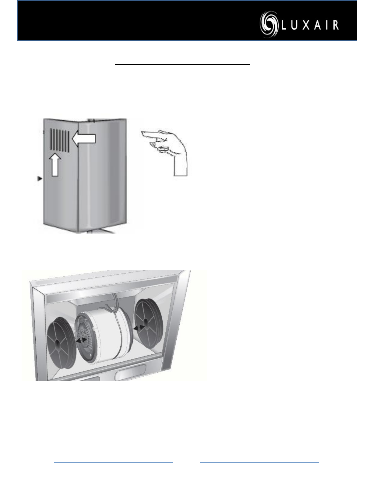
Please note that if the hood is
not to be vented to an outside
wall, the top section of the hood
with the vents must be used,
this allows the filtered air back
into the room. Failure to do so
will result in the hood been
noisy and will cause it to
vibrate; this will also void the
warranty if this section is not
used when installed in
recirculation mode.
Note that when the hood is not
vented to an outside wall,
charcoal filters ust be used in
Conjunction with the above
vent system.
For fitting instructions please
see pages …..
Page 9

Page 9
1) Unpack the hood and inspect the goods carefully, please
check for any cosmetic damage before installation begins,
Luxair will not accept liability for cosmetic damage after the
hood has been installed, if damage is found then please contact
the retailer from where the goods were purchased.
2) Check that all parts and fixings are packed in the box.
3) Do not remove any of the protective film until installation is
complete, this will
help reduce any accidental damage and help
prevent scratching.
4) Remove the metal Grease filters immediately after opening
packaging and storein a safe place, they will not be needed until
installation is complete, this will
also ensure against accidental
damage of the filters.
5) You must use either a ducting kit or charcoal filters with all
Luxair hoods.
6) All filters and ducting kits can be purchased from our website
www.luxairhoods.com
Before Installing Your Hood
Page 10
Page
10
2
3
4
6
5
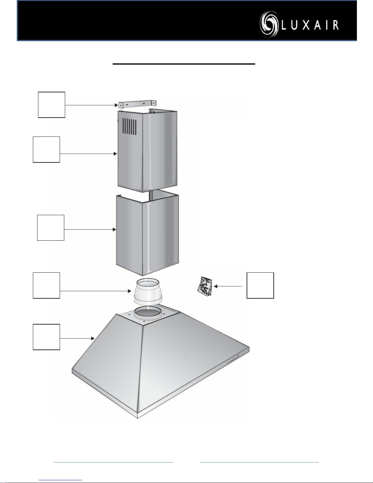
1 Wall Bracket
2 Top Chimney Section with Vents
3 Bottom Chimney Section
4 Reducer
5 Main Body
6 fixing screws
Hoods Check List - Standard
1
2
3
4
5
6
Page 11
Page
11
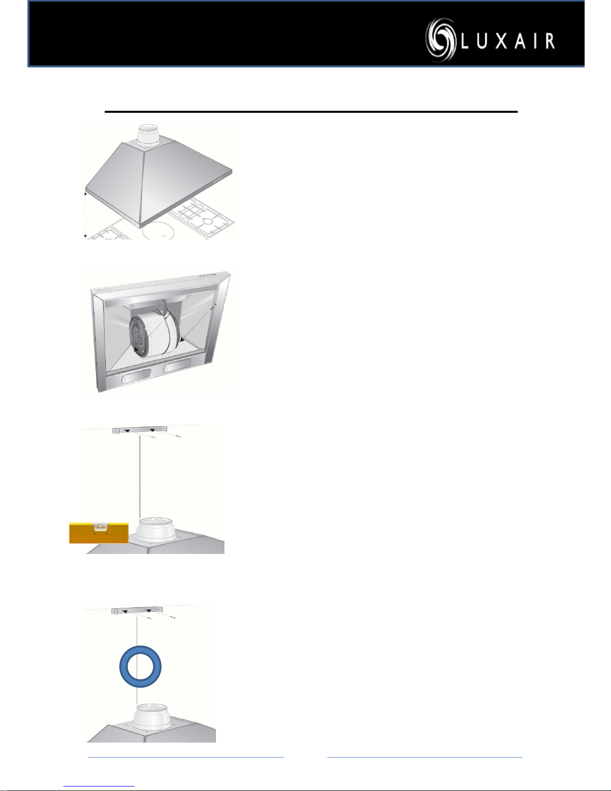
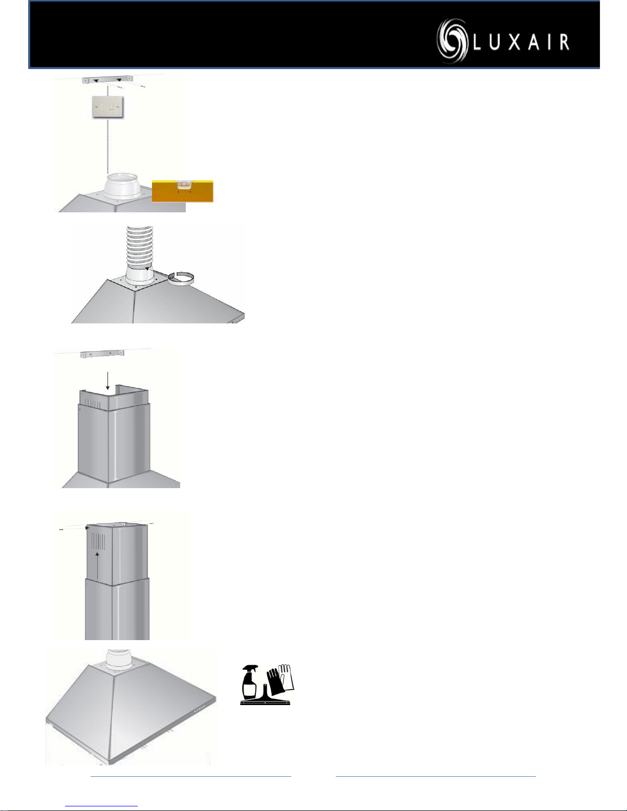
Fitting Instructions – All Wall Mounted Hoods
1
Position the cooker hood body
directly above your hob, make
sure that you comply with the
minimum height regulations set
out on page 10 and 12
2
Secure the main b ody of the
hood to the wall. Make sure
that the fixings are adequate for
the type of surface you are
fixing to.
Luxair provide some screws but
they may need changing
depending on the type of wall
yo u have, if yo u are in an y
doubt then seek professio nal
advice.
3
Measure the desired height of
yo ur chimney sections.
Measure the center of the main
body section of the hood and
then draw a straight vertical
line, place the metal u shaped
bracket at desired height center
to your line and secure the
bracket to the wall.
4
Mark the height and position of your
ducting hole; this should be a
minimum distance from top o the
hood to the center of your hole
250mm.
Remove the hood of the wall before
drilling the ducting position; this will
stop any debris from falling into the
fan housing and avoid any damage.
Page 12
Page
12
5
Mark the height and position of your fused spur
socket position this so it’s accessible, this should
also be fused with a 3amp fuse. Remove the
hood off the wall before drilling for the electrics
6
Move the bod y section to the wall
and proceed to make all electrical and
ducting co nnections, make sure you
have complied with all safety
instructions as outlned in the booklet.
7
Once all electrical and ducting has being
connected and tested proceed to assemble the
chimney sections, place the bottom part of the
chimney into the body of the hood , no fixings
are required as the
grooves secure this part, slide
the top section into the b ottom section
of the chimney, taking care not to scratch this as
you do so. The vented top section can be turned
upside down if the hood is ducted outside, this
will hide the vents that are unnecessary for
ducted out use. See page 12 for more details on
vented or recirculated options
8
Slide the top section into place over
the wall bracket, take care not to
scratch this as you do so, and secure
the top section to the bracket with
the two short screws provided.
Your new hood is no w read y for
use
Warning
Do not attempt to clean down your
new hood until you have read the
cleaning instructions
Careless cleaning could bur
and scratch your new hood
Page 13
Page
13
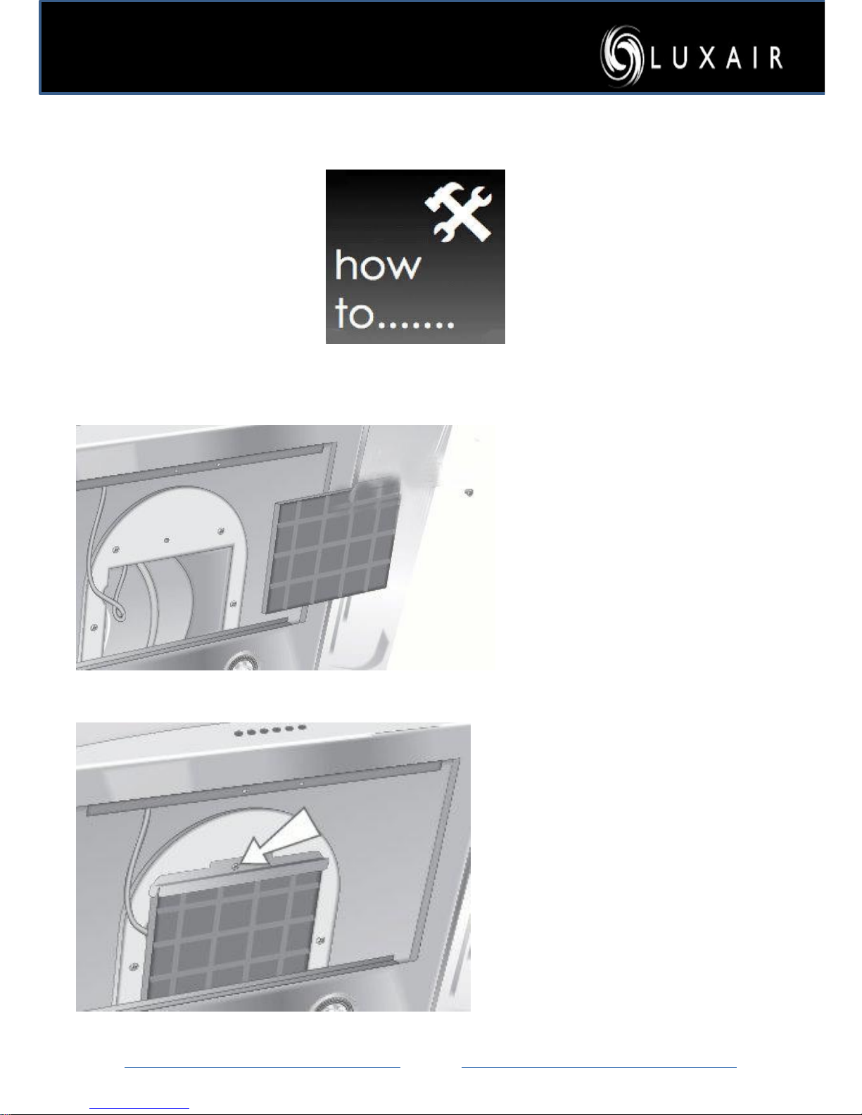
How To Fit Square Charcoal Filters
1
Remove the metal grease filter
to reveal the inner flue section.
2
Make sure all wires are pushed
to one sid e preventing
snagging.
3
Offer the filter to the bottom
and back the flue section and
insert into back L-shaped
bracket.
Push the filter into place and
secure with the front screw as
opposite.
Please note that the filters are
only necessary for hood s that
are not vented to an outside
wall and must be replaced
every 50 hours or two- three
months.
Page 14
Page
14
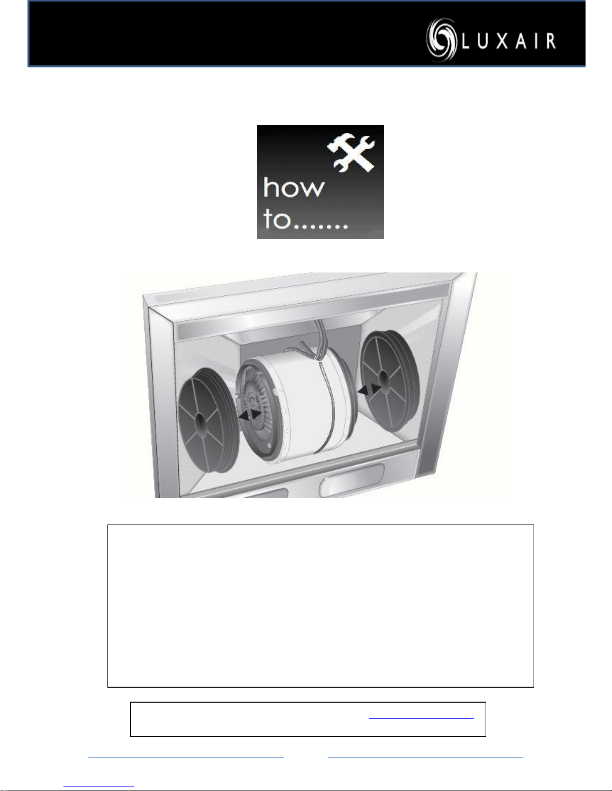
How To Fit Round Charcoal Filters
Offer the round filter to the side of the motor housing.
Twist Clockwise Slowly until you feel the filter sit.
Twist clockwise until you feel it lock
Reverse the process to remove
Please note that charcoal filters will need replacing every 2 months or every
50 hours of cooking. Failure to replace these filters will result in the warranty
being void..
For Replacement filters please visit our website at www.Luxairhoods.com
Page 15
Page
15
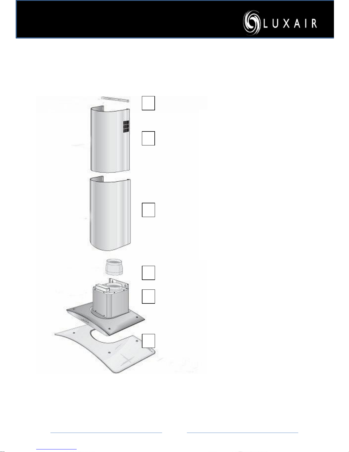
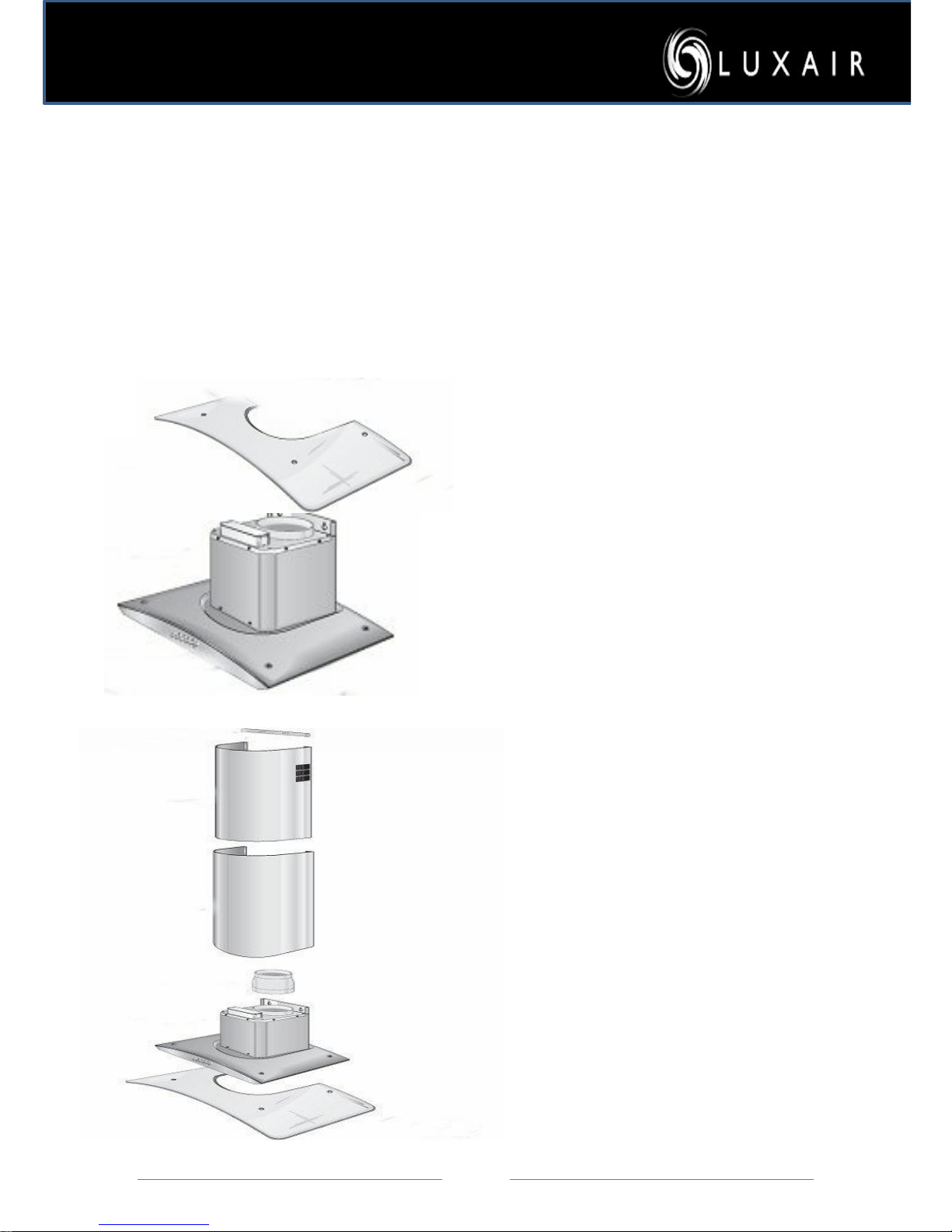
Hoods Checklist – Curved Glass/Straight Glass
1
2 3 4
5
6
1. Wall Bracket
2. Top Chimney Section
3. Bottom Chimney Section
4. Reducer Collar
5. Body Section
6. 8mm Safety Glass
7. Fixing Screws
Page 16
Page
16
Fitting Instructions – All Glass Hoods
Follow Fitting Instructions for all wall mounted hoods pages…..
Then Continue with this section.
1
After following instructions 1-9 on
pages 18-20 continue with this
section for the rest of the fitting of
this hood.
Once the hood is assembled and
checked, place your glass directly
on top of the main body section, line
up with the screw holes and secure
with screws and washers.
Warning: do not over tighten these
screws, they should be hand tight
only. Over tightening may cause the
glass to break
2
After fitting the glass, now fit the
two telescopic chimney section,
please ensure that you do this with
care, slide the top section up to the
fixing bracket, and secure with the
two small screws in the fixing kit.
Page 17
Page
17
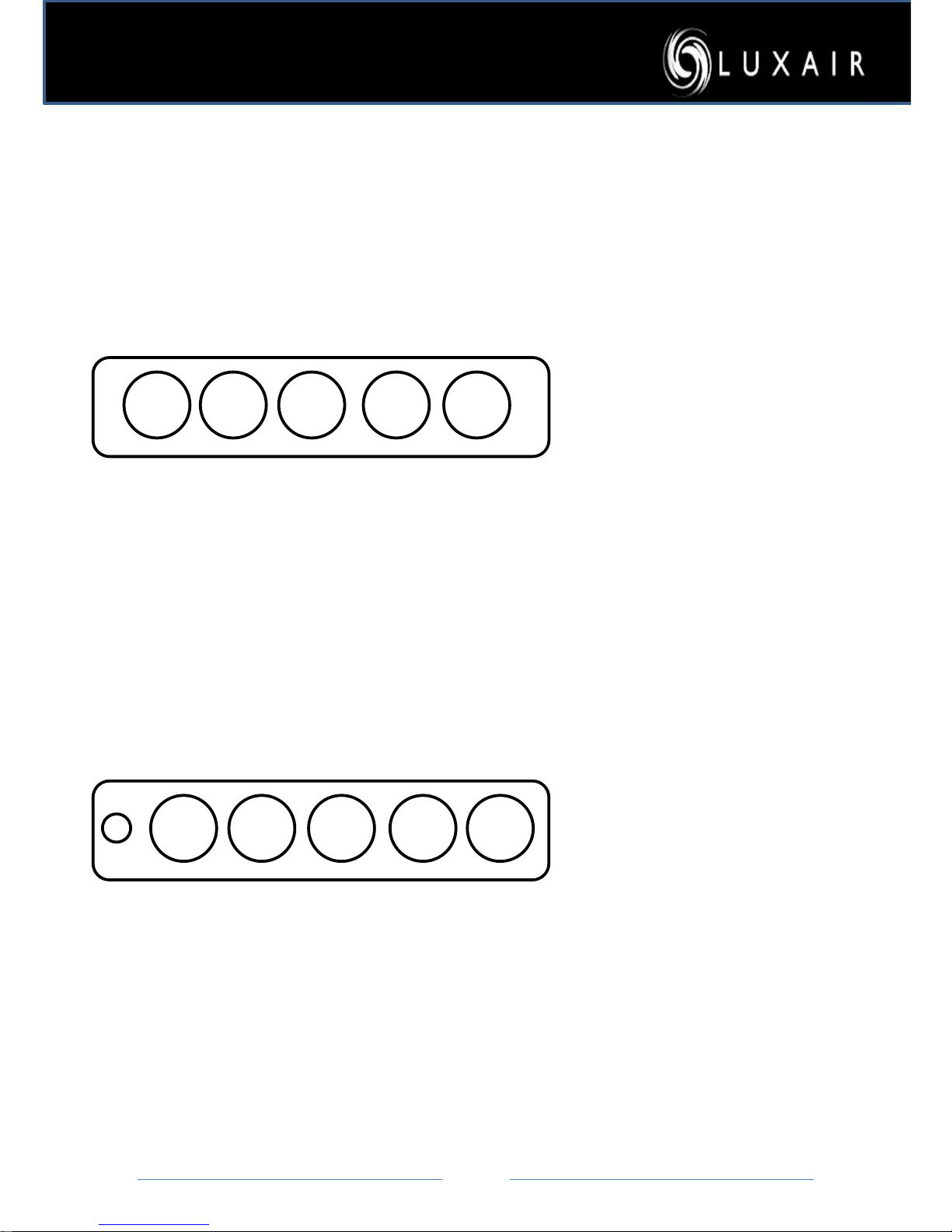
Operating Your Hood
2 13 * T
1: Select speed one to activate your
fan, then
speed 2 and so on.
2: To turn on the lights press the light
switch.
*
3: The T button is a timer switch, when
pressing the T button it will start to
flash! This
means you have activated
the timer unit, your
hood will then
turn its self off after 20mins, to cancel
this simply press the T button again.
4: If the light button starts to flash,
simply
press and hold it for 3 seconds
to deactivate
5. If The 1 and * button is flashing this
needs resetting by turning the * on,
then turn the * off then hold * for 10
seconds
I 0 II
*
III
Electronic Switches
Push Button Switches
1: select speed I to activate your fan,
then
II and so on.
2: to turn on the lights press the light
switch.
*
3: To Turn off your hood press 0
button
Page 18
Page
18
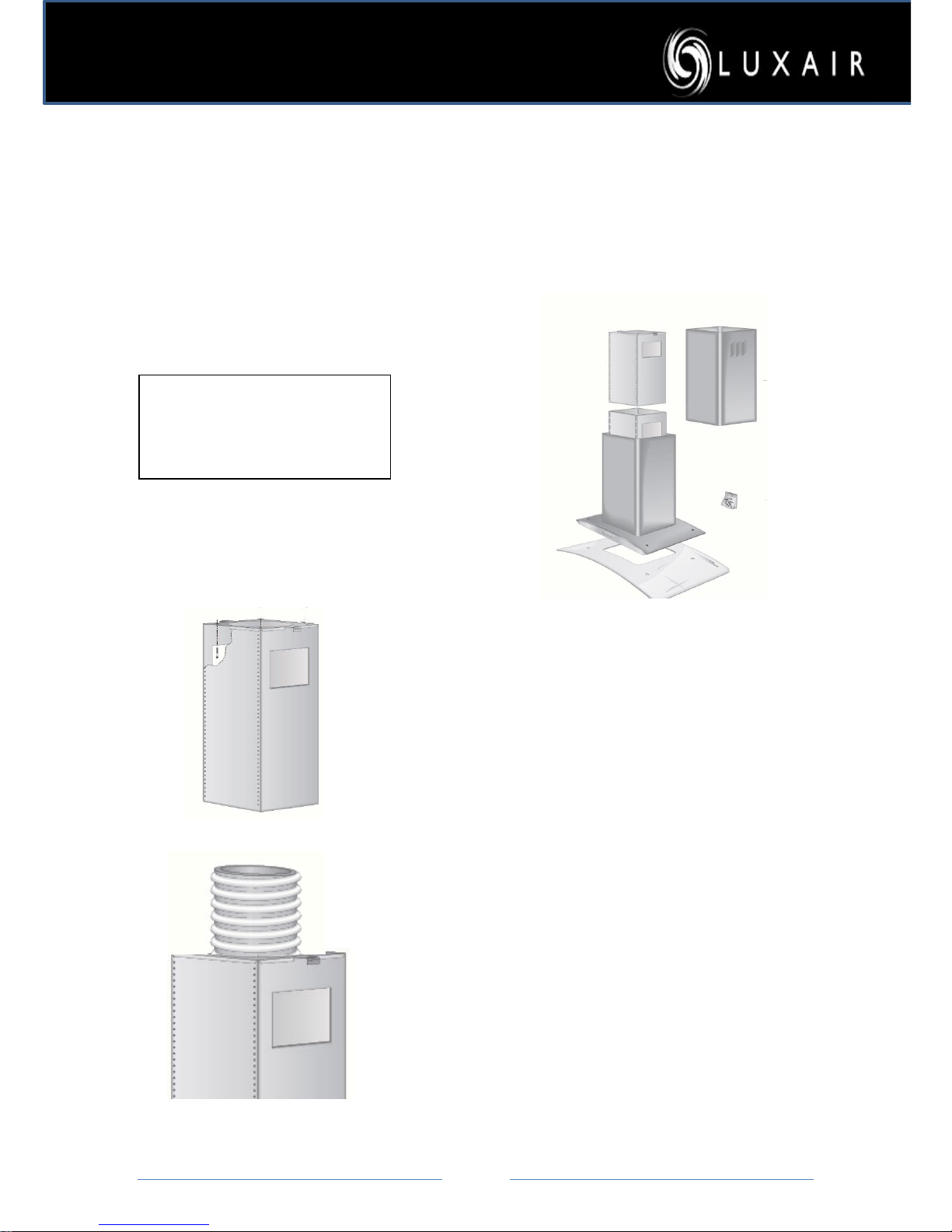
Installation- all Island hoods
Please note: All Luxair Islands are installed in ex actly the s ame manner and it is
only the shape and design that differ, please use the following steps for all Island
unit models
Please note that the installation of all Island hoods should be
carried out by at least two people.
1
Position the inner top section of
the upper arm directly on the
ceiling and above your hob and
mark the center hole, also mark
fixing
positions. Make sure you are
center to your hob.
2
Make sure that your fixings will
hold at least 75kg in weight; this
must
also be flush with the ceiling.
Drill a 150mm hole in the ceiling
and
connect your ducting, run it to
the outside wall, this must not
exceed 4mtrs in length.
3
Pass the ducting hose and
electrical cable through the center
hole of the Ceiling top inner arm.
Proceed to secure the arm to your
ceiling using either coach screws
(provided) or coach bolts (not
provided). It is paramount
that these fixings are strong
enough to hold the weight of the
hood.
Warning:
All Island hood must be flush
mounted and under no
circumstances must the chimney be
inset into the ceiling void.
Page 19
Page
19
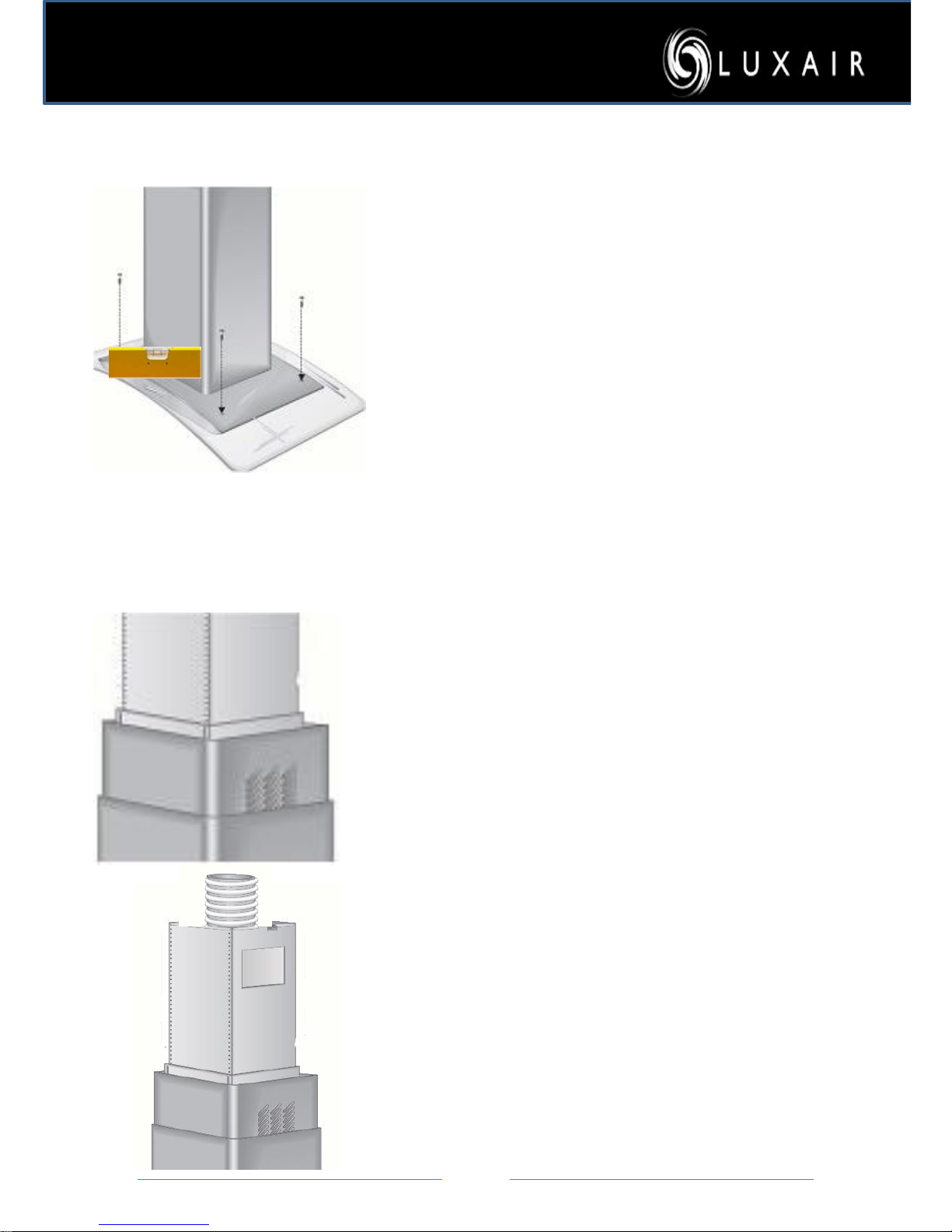
4:
Before you go any further
assemble the glass (applicable
to glass units only) over the
main body of your hood and
secure with screws and
washers (provided).
Do not over tighten these
screws as you may cause the
glass to shatter.
5:
Insert the top stainless steel
chimney section into the bottom
stainless steel section; take care
not to force this as you may
cause damage.
6:
Lift the whole unit up onto the
main pre fixed upper inner arm,
slide it up or down to correct
height, make sure that you have
allowed the minimum height
above your hob unit.
.
Page 20
Page
20
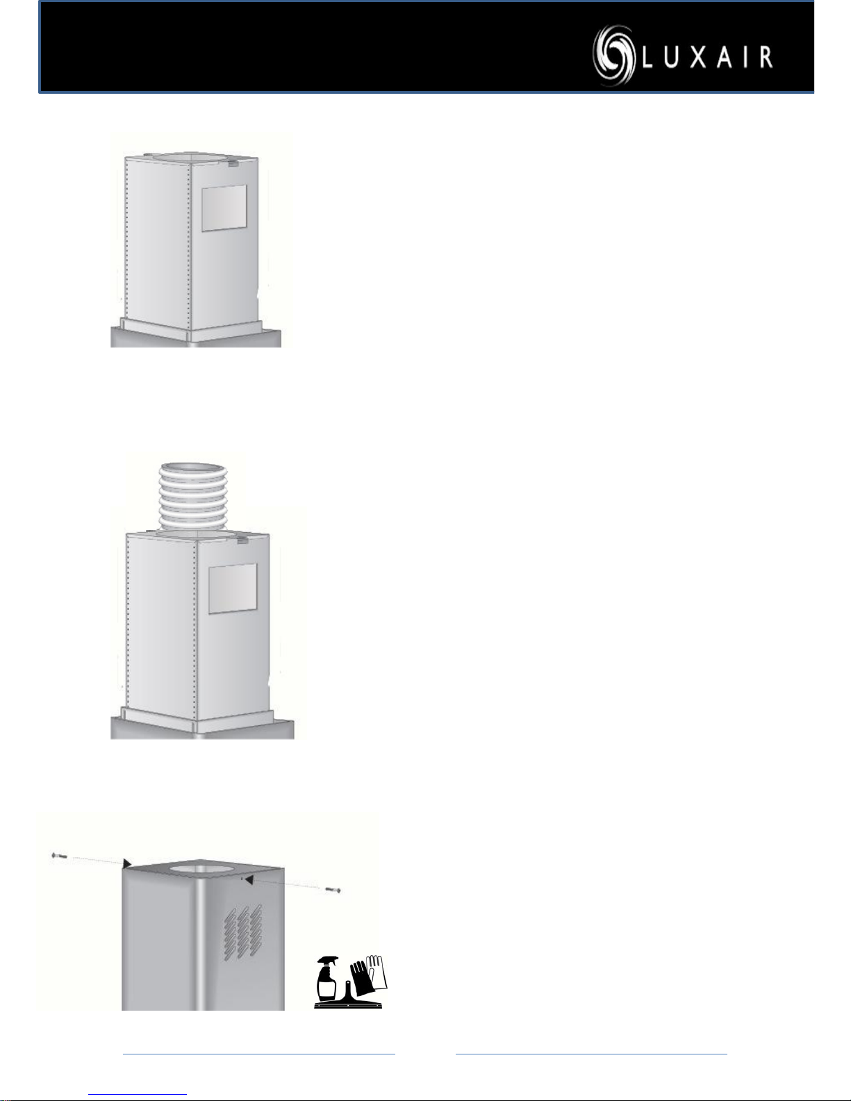
7:
When you have selected the
correct height above your hob
secure the inner bottom section
of the flue, to the inner top
section of the flue in the fixing
positions as opposite. Your
cooker hood should now be
secure.
8:
Make all final ducting and
electrical connections through
the specially cutout hole. Test
that all ducting and electrical
connections are working before
completing the final part.
9:
Finally, lift the bottom outside
stainless steel section upwards,
(take care not to scratch this
section), and secure to the two
top mounting brackets with
screws (provided).
See cleaning
instructions on
page
Page 21
Page
21
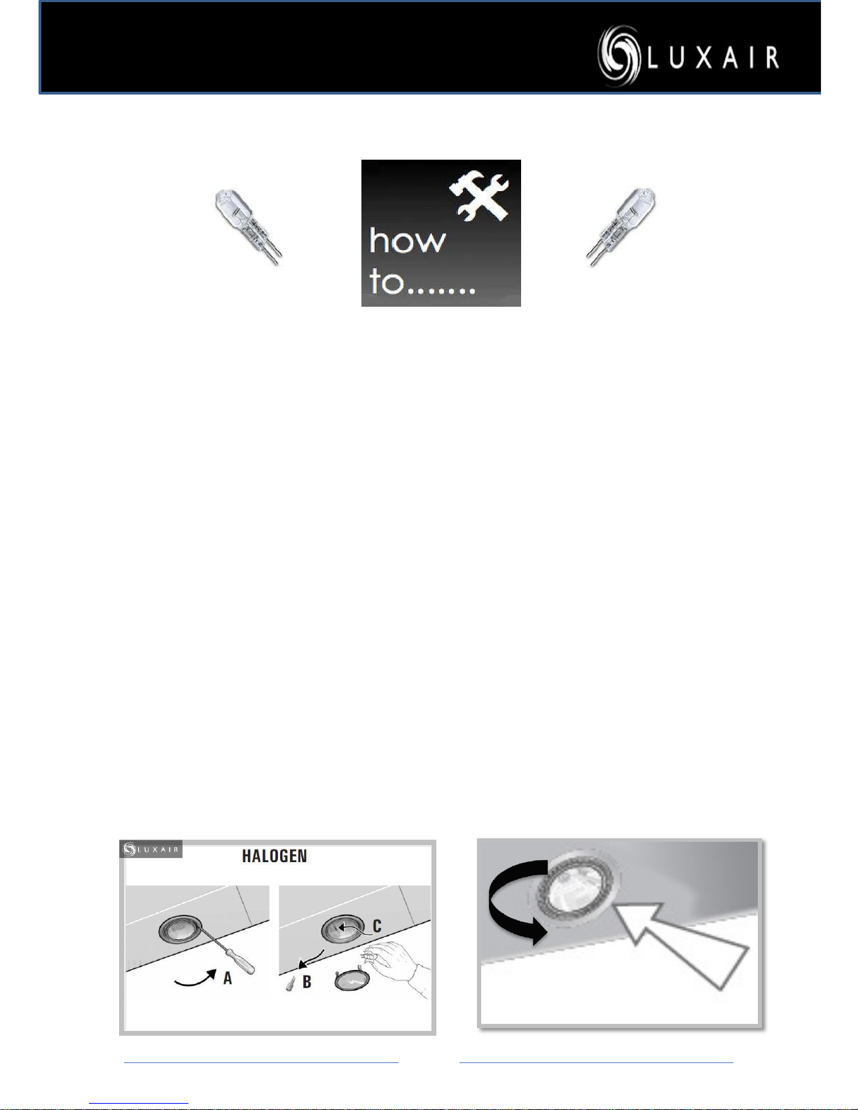
How To Change A Halogen Light Bulb
How to change a halogen bulb?
Replacing Your Cooker Hood Halogen Bulbs
1. Please make sure that your cooker hood is switched off at the mains before any work is carried out on
your extractor.
2. Do not remove the hood light fitting. Changing the halogen light bulb is done from underneath your
cooker hood.
3. Take a small electrical screwdriver (Fig A). Remove the black plastic ring (or steel ring dependant of the
extractor type) carefully, be aware that the glass will also be released at the same time so ensure that you
place a soft cloth under your extractor fan just in case the glass lenses fall.
(If your Lights do not have the inner Black/steel ring and are just a plain brushed steel fitting, then this will
need to be twisted instead to gain access to the bulb SEE IMAGE 2)
4. Now remove the halogen light bulb from the light fitting. Please note that the halogen bulb has two long
prongs and will need to be removed by pulling firmly sideways!
5. Once you have removed the old bulb, replace with the new one. Be aware that you must not touch the
new bulb with your fingers; use a cloth or tissue to insert the new bulb. The reason for this is that halogen
bulbs over heat and pop if grease or oil is present on the glass.
6. Repeat above process to replace the lens and clips.
Bulbs are not covered by warranty and can be purchased from all major Diy stores or your local electrical
retailer.
Image 1
Image 2
Page 22
Page
22
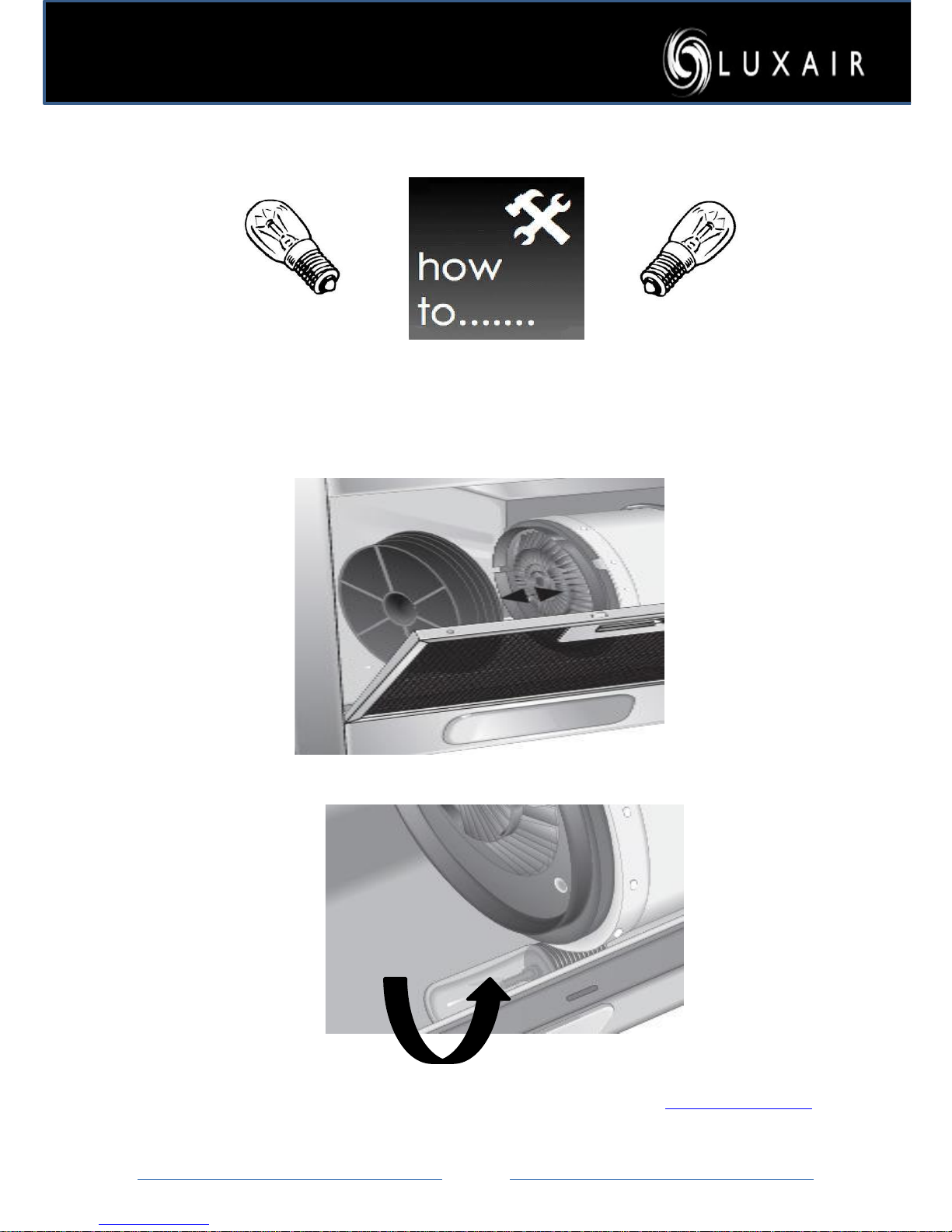
How To Change Screw Light Bulb
Screw Bulbs
1. Remove the metal grease filters from your hood to expose the light fitting
located at the back of your hood,(this only applies to standard hoods)
2. Twist the bulb anticlockwise to remove, replace with a 20/40 w max screw
bulb.
Bulbs are not covered by warranty and can be purchased from the Luxair Website www.luxairhoods.com
Page 23
Page
23
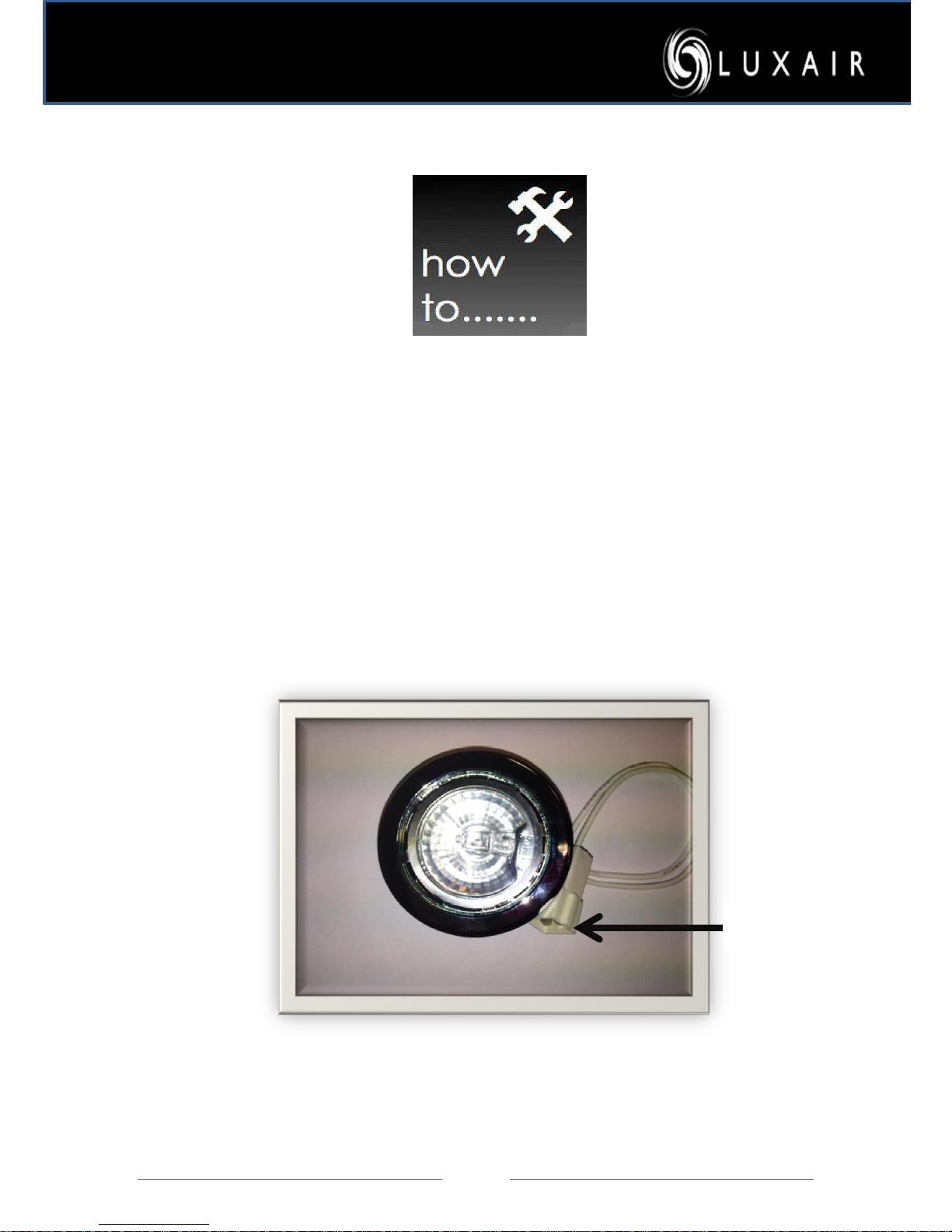
How To Change A Cooker Hood Light Fitting
Replacing your Cooker Hood Light Fitting
1. Remove your Metal grease filters to allow you access to the inside of the hood.
2. Once removed you will be able to push the light fitting out from inside the hood
3. You will now be able to see the connector which you can now disconnect and reconnect
the new light fitting.
4. Now push the fitting back into place
Connector.
Page 24
Page
24
Before You Call Us – Most Common FAQ’S
Below are a few checkpoints you need to carry out before you call us; unnecessary phone
calls
can be avoided by checking before you call, Please note that Luxair cannot be held
responsible for incorrect
installation of the ducting system, any problems relating to this
matter must be taken up with the person or persons who installed you hood
Noisy/Vibrating Hood
Check if the ducting is too small (has to be at least 5inch 125mm)
Check that the hose fits over the outside of the plastic collar.If the ducting is connected to the
inside of the collar this is incorrect and must be replaced with 125mm duct. See page 7
Check if the ducting is obstructed in any way with debris that may have fallen in during
installation
If the ducting is 5 inch, check to see if the hole the ducting has been pushed through a smaller
than 5 inch hole. (if it has been fitted into a 4” hole this is the same as using 4” ducting and
voids the warranty)
To be 100% certain the ducting is the cause of the vibration Disconnect it, and then switch the
cooker hood back on, If the noise has stopped then you need to contact the installer as
installation error are not covered by your warranty.
Check to see if all fixtures and fittings have been used, all screws must be used during
installation and chimney must be securley fixed and has at least 4 fixing screws.
If Recirculated Check the flaps on the motor have been removed and the the bolts have been
securley tightened.
If recirculated check to see if they have the vents showing on the top chimney section to allow
the air to get out of the hood and that they are not obstructed or blocked, see page 8
Please Note: If hood is on a pertition or stud wall, this will cause vibration and cause the hood
to be noisey due to the wall being hollow
Poor Extraction
Check the ducting size (125mm see page 7), If the ducting is run too far, over the recommended
3.5mtrs. 5.5 mtrs on island hoodsthis can also add to vibration if thevertical lift is higher than
2.5mtrs, airbecomes heavy and caused a downfall or return, thusCausing the motor to reverse
and Vibrate.
If your ducting has too many bendsor elbows this can also cause poorextraction rates, please
note thatevery time you use an elbow or bend in the ducting run, you will lose up to a third 1/3
of its extraction rate per elbow. Try to avoid too many bends
Please Note: If Your hood is Recirculated you will lose 30% of the power than if ducted out. Also
Check for vents in the chimney – The hood needs the vents if it is recirculated to allow the air to
be let out of the hood.
Turn the hood on at speed 1, Take an A4 piece of paper and place it flat on your hand, then offer
it up to the metal grease filters, place the paper Up against the filters and remove your hand, the
paper should stay in place, if it does not then you need to check the ducting or call the person
who installed the hood.
Please Note: Cooker hoods will only remove 60% of the steam or vapors when Cooking,
they do not extract all Vapors the minute the extractor is Turned on, a vortex is created
in the room thus allowing it to clear all vapors usually within one hour. Before calling us,
please take note of the points set out in this manual, if you are in any doubt then please
seek professional qualified assistance.
Page 25
Page
25
Cleaning And Care
Before carrying out any cleaning or maintenance work, disconnect the
cooker hood from the mains supply.
Ensure that:
– it is switched off at the wall socket and the plug withdrawn, or
– the fuse is withdrawn from the fused spur connection unit, or
– the mains fuse is withdrawn, or
– the screw-out fuse is removed (in countries where this is applicable).
The surfaces and controls are susceptible to scratches and
abrasions. Please observe the following cleaning instructions
.
All external surfaces and controls can be cleaned w i th warm water and a
little washing-up liquid applied with a well wrung-out soft sponge or
cloth. Wipe the surfaces dry using a soft cloth.
Do not use too much water when cleaning the controls. Water could
penetrate into the electronics and cause damage.
Page 26
Page
26
Do Not Use:
– Cleaning agents containing soda, acids, chlorides or solvents,
– Abrasive cleaning agents e.g.
powder cleaners or cream cleaners, and abrasive sponges, e.g. pot scourers or
sponges which have been previously used with abrasive cleaning agents. These will
damage the surface material.
Controls
The controls may suffer discoloration or damage if soiling is left on them for too long.
Remove soiling straight away.
Never spray cleaning products directly at the control or switch panels.
Glass surfaces
Glass surfaces can be cleaned using a proprietary non-abrasive cleaning
agent designed specifically for use on glass. Avoid oven sprays.
Cleaning the grease filter by hand
•Clean the filter with a soft nylon brush in a mild solution of hot water and a little washing-up
liquid. Do not use "neat" washing up liquid.
Do not use:
– Cleaning agents containing descaling agents,
– Alkaline cleaning agents (with a pHvalue higher than 7), such as powder cleaners, cream
cleaners or abrasive all-purpose cleaning agents,
– Oven sprays.
Cleaning the grease filter in the dishwasher
•Place the filter with the short sideupright in the lower basket, and washon a 65°
programme using a mild Dishwasher detergent; ensuring the spray arm is not
obstructed.
Avoid alkaline dishwasher detergents (with a pH value higher than 7). Depending on
the cleaning agent used, cleaning the filter in a dishwasher can cause permanent
discoloration to the surface. However, this will not affect the functioning of the filter
in any way.
•After cleaning, leave the filter to dry for a while on an absorbent surface
before putting it back in place.
Page 27

Page
27
Total connected load* . . . . . . . . . 240 W
Fan motor*. . . . . . . . . . . . . . . . . 200 W
Hood lighting . . . . . . . . . . . . ..2 x 20W
Halogen lamps
Osram type 44888 WFL, 20 W
Voltage
UK, NZ, ZA . . . . . . . . . . . . . . .AC 230 V
Frequency . . . . . . . . . . . . . . . . . .50 Hz
Fuse rating (UK). . . . . . . . . . . . . . 3A
AUS, NZ:
Plug rating . . . . . . . . . . . . . . . . . . . 3 A
Test marks . . . . . . . . . .Electrical s afety
. . . . . . . . . . . . . . . . . . . . .. C-Tick Mark
Elec trically suppressed
according to AS/NZS 1044
Electrical cable length . . . . . . . 1.5 mtr
Fan performance wall mounted
hoods
Extraction power according to
EN 61591
0
Extraction sys tem
150 mm:
Level I . . . . . . . . . . . . . . . . . . .200 m/h3
Level II. . . . . . . . . . . . . . . . . . .300 m/h3
Level III . . . . . . . . . . . . . . . . . . 650 m/h3
0
Extraction sys tem
125 mm:
Level I . . . . . . . . . . . . . . . . . . .180 m/h3
Level II. . . . . . . . . . . . . . . . . . .280 m/h3
Level III . . . . . . . . . . . . . . . . . . 550 m/h3
Unrestricted . . . . . . . . . . . . . . .680 m/h3
* For EXT models, the connected load
and ex traction power will depend on
the type of external motor fitted.
EXT models:
Length of connection cable to external
motor . . . . . . . . . . . . . . . . . . . . . . .1.9 m
Decibel ratings
Noise Level Min/Max (CBM/H) Speed 1 = 37.5DB
Speed 2 = 46.9DB
Speed 3 = 56.9DB
Fan performance Island Hoods
0
Extraction system 125 mm:
Level I . . . . . . . . . . . . . . . . . . .280 m/h3
Level II. . . . . . . . . . . . . . . . . . .380 m/h3
Level III . . . . . . . . . . . . . . . . . . 800 m/h3
Unrestricted . . . . . . . . . . . . . . .890 m/h3
Technical Information:
Page 28
Page
28
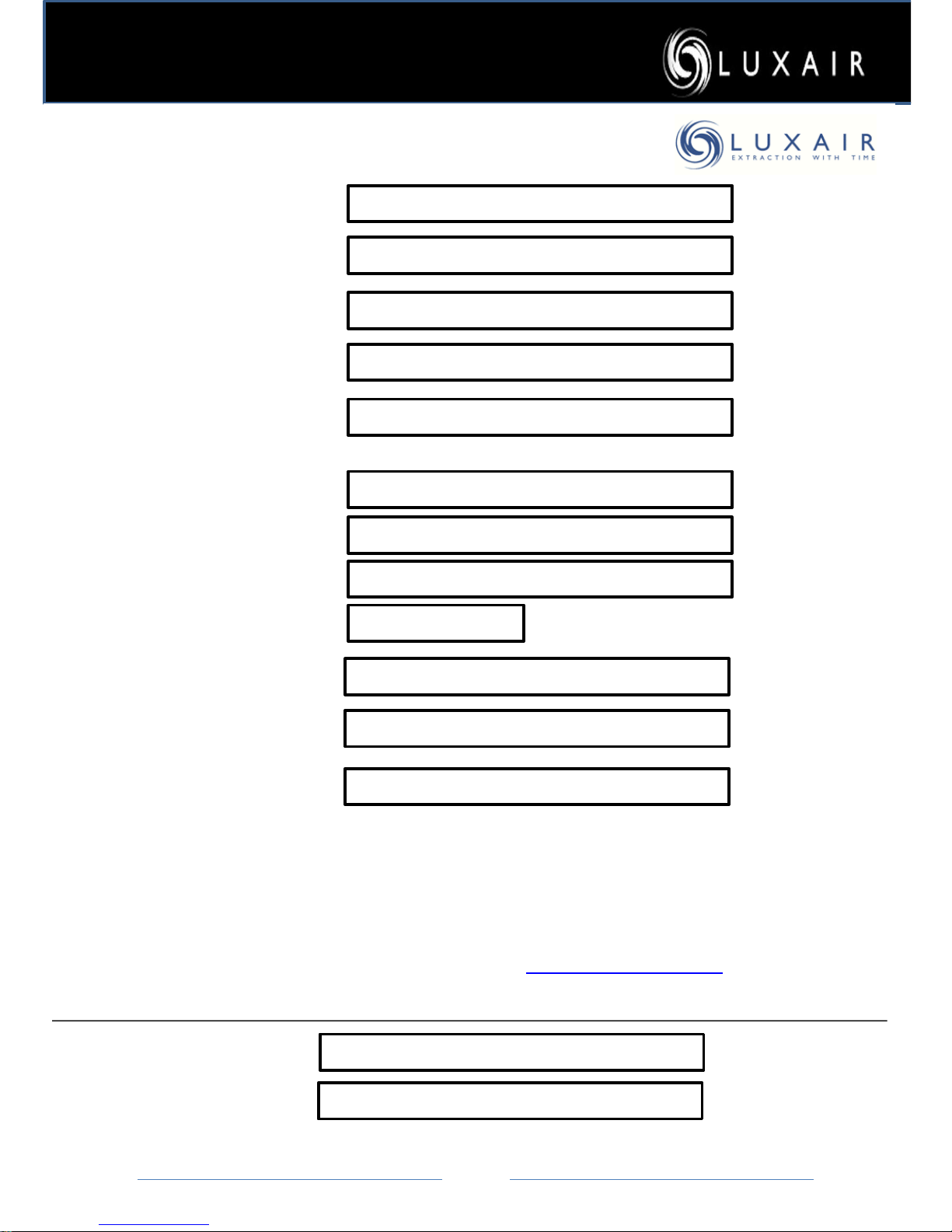
WARRANTY FORM
---------------------------------------------------------------------------------------------------------------------------------------------------------------
Name:
Contact Name:
Phone Number:
Mobile Number:
Email Address:
Postal Address
:
----------------------------------------------------------------------------------------------------------------------------------------------------------------------------
HOUSE NAME OR NUMBER:
ADDRESS:
TOWN OR CITY:
POSTCODE
----------------------------------------------------------------------------------------------------------------------------------------------------------------------------
Serial Number:
Model Number:
Ducting Size(If ducted)
Please note: this box must have the correct serial number and model number in order
To activate your warranty, this form must also be returned to Luxair within 31days
After installation in order to receive the extended warranty on our products.
Once we receive your Warranty registration you will receive a warranty confirmation letter, please keep this safe in
the event of a claim, If you do not receive this after 14 days of registering please contact Luxair.
Warranty’s can also be registered online at WWW.LUXAIRHOODS.COM
Purchase Details:
Purchased From:
Date Purchased:
See back page for address details.
Page 29
Page
29
Lux Air Policy
PLEASE NOTE: All ducted out hoods must use a five-inch (5") ducting, failure to do so will result
in the warranty being void. In addition, all hoods must be surface mounted and free from
obstructions, and fitted with a 3amp fuse.
Luxair Terms & Conditions
Luxair cooker hoods operate a policy of continuous improvement and reserves the right to adjust and modify its
products and prices without prior notification. All the Operational Extra Kits can be purchased if required.
PLEASE NOTE:
All Luxair kitchen extractors must be installed by a qualified electrician, under no circumstances do we
recommended that these appliances be installed by you personally unless qualified to do so. All hoods must be
installed in conjunction with the installation manual.
LUXAIR TERMS AND CONDITIONS
Service Call Check list
Service call check list before calling our service departments please ensure that the following checks have
been done:
All electrical connections have been installed by a qualified electrician and that a fused spur of 3 amp has
been installed for safety.
Please note if the appliance is found to be a faulty or inadequate installation you will be charged for the call
out and parts needed to rectify the problem. Please also make sure your cooker hood is free from
obstruction, this includes cookers hoods that may be tiled in and have a fly over shelf, in order for our
engineers to have easy and unrestricted access. Any cooker hood that are obstructed will need to be
removed prior to our engineer’s arrival at your own cost. Your statutory rights are not affected.
All parts purchased for hoods not in warranty will receive a 12 month manufacturer’s warranty as standard.
All models must be installed on 125mm ducting. Failure to do so will result in your warranty being invalid
and any service call will be chargeable as well as parts used to rectify the fault.
Information Supplied
You should ensure that any information supplied by you is correct before proceeding to payment. Luxair UK
Limited does not accept responsibility or offer refunds if you provide incorrect information. We will not be
held responsible for any errors made by you entering incorrect information.
The information is available on the Website are provided on an "as is" basis without any representations or
endorsements made and without any warranty of any kind whether express or implied, including but not
limited to implied warranties of fitness for purpose, merchantability and accuracy.
Nothing contained in the Website is intended to constitute legal advice of any sort, and the basis on which
you acquire or make use of any information or document is that the information or technical advice is
suitable for use by you in conjunction with proper advice as to its application and adaptation for your
particular requirements. We will not have any liability to you at all if you use any information or advice
without obtaining appropriate legal advice nor will we have any .esponsibility at all for any alterations made
to the appliance after you have received it.
hyperlinks to such websites does not imply any endorsement of views, statements or information contained
Page 30
Page
30
The Website may contain hyperlinks to websites operated by other parties. We do not control such
websites and we take no responsibility for and will not incur any liability in respect of, their content. Our
inclusion of hyperlinks to such websites does not imply any endorsement of views, statements or
information contained in such websites.
The information within this website and any downloaded media from this website is provided subject to
the condition that it shall not, by way of trade or otherwise, be lent, re-sold, hired out or otherwise
circulated without the publisher's prior consent in any form of than that in which it is published and
without a similar condition including this condition being imposed on the subsequent purchaser.
Images used on Luxair’s Website may differ from the actual product, this will only include images of the
switch/control panels that have been modified and improved during production of goods. All images
displayed give a true representation of goods.
The information is provided on the understanding that the website is not engaged in rendering legal
advice. Furthermore no liability can be accepted for loss or expense as a result of using this website. By
using the Website you agree that in no circumstance shall The Company be liable for any indirect,
incidental, special or consequential damages, including, but not limited to, loss of business or profits or
any other financial loss, arising out of or in any way connected with the use of the Website, under any
law or on any basis whatsoever whether contractual or otherwise.
Manufacturer’s Warranty
*7 Years parts and labour warranty must be registered within 31 days of installation to be eligible for the
free extended warranty. If not registered in this period then a 12 month standard manufacturer’s
warranty applies without any product registration. Proof of purchase may be required in the event of a
claim. Once your product is registered you will receive confirmation via email or letter for you to keep as
proof of registration. If you do not receive confirmation within 14 days of registering please advise
Luxair immediately. It is advised if registering via post to send recorded delivery in the event that we do
not have your registration on record in which proof of postage will be accepted. If sent via standard
delivery Luxair cannot be held responsible for any warranties lost in transit, it is your responsibility to
ensure your warranty form has been registered or alternatively register online.
Any goods purchased as end of line stock or ex display models will receive a standard 12 month
manufacturer’s warranty and do not qualify for the 7 years extended warranty.
Availability
All products are subject to availability and may be changed at any time.
If your order cannot be fulfilled you will be offered an alternative or given a full refund.
If an order is received for a discontinued product we will automatically provide you with the up-to-date
equivalent, providing it is available and the same price as the discontinued model. If this is not the case
we will contact you.
Luxair will not be held liable for any cost incurred due to delay in production/delivery of goods. All goods
are manufactured in Italy and delivery dates cannot be guaranteed as there may be unexpected delays
in the production, however we aim to keep stock of items to keep disruption to a minimum.
Delivery
Upon delivery a signature will be required.
Delivery dates are estimated at all times and may be delayed without prior notice (e.g. due to sudden
stock shortages, manufacturing delays, or delivery vehicle breakdowns), which is why we strongly
advise all customers not to book fitters until they have received the relevant goods, as no claims will be
accepted. We shall not be liable for any losses, costs, damages, charges or expenses caused by any
delay in delivering goods.
Page 31
Page
31
The day before delivery we endeavour to advise all customers of an estimated AM/PM timeslot.
You will be notified of your delivery timeslot by telephone between 9am and 5pm the day before
delivery providing you have given us sufficient contact details.
You cannot choose your own delivery timeslot as these are allocated by our automated route planning
system. Once issued your timeslot cannot be changed, therefore someone must be present at the
delivery address and able to accept the goods upon arrival of our delivery vehicle.
Once a delivery date has been agreed with yourself you must be in to accept delivery or advise Luxair
of an alternative delivery address 24 hours prior agreed delivery date. Any redelivery of goods will be
subject to an additional delivery charge and will delivered at the next available date.
Next day deliveries are available upon request and any additional delivery charges will need to be paid
prior to Luxair arranging this service. Please contact Luxair for prices to your area.
Exchange or refunds of goods
Luxair will exchange any goods found to be damaged on delivery, you must inspect the goods at point
of delivery and inform Luxair within 48 of any damages, any damages reported after this time will not be
exchanged. We will require photographic evidence of any damages incurred to your goods.
Please check the goods and inspect them before you sign for them. Goods that have been received as
damaged and proceeded to be installed will not be exchanged or refunded as these have been
accepted as seen.
Return of Unwanted Goods
Luxair must be notified within 7 days if goods are no longer required or have been purchased in error.
We will refund in full or replace damaged or faulty goods only if installation has not taken place.
Unwanted goods must be returned at your own cost and will be subject to a 25% restocking fee.
All goods must be returned in perfect resalable condition and unused and have not been subject to
installation. If installation has taken place the return will be rejected and are non-refundable.
You have a duty of care while the goods are in your possession and we reserve the right to charge you
for any damage that may have occurred during this period.
Goods that have been installed and found to be faulty must be treated as a service call and it is up to
you the purchaser to instigate the service call. Goods damaged by incorrect installation procedures or
by an unqualified electrician will not be exchanged or replaced however spares can be purchased at an
additional cost to you to help rectify the situation.
Goods found to be faulty ( not damaged) for example, not working, faulty components or shoddy
workmanship will be sent out for a service call, all faulty goods must be reported within 7 days of
delivery.
Changes to Terms and Conditions
Luxair may at any time revise these terms and conditions and any revision will accordingly supercede
these terms and conditions. Users will therefore be bound by such revised terms and conditions and
are advised to regularly review this page.
Entire Agreement
This Agreement constitutes the entire agreement between us concerning its subject matter.
General
Your statutory rights are not affected.
Page 32

Page
32
Lux Air UK,
Lux Air House,
Unit 2 & 5, Keld Close
Barker Business Park,
Mel merby,
Ripon
North Yorkshire
HG4 5NB
Telephone: OO44 (0) 1765 641888
Fax
: 0044 (0)1765 641889
Help Line
0044 (0) 1765 641888
Email:
Web:
www.l uxairhoods.com
Alteration rights reserved / 1306 M.-Nr. 06 783 600 / 02
en - GB
 Loading...