

Luxair LA-60-1100 CVG GLASS, LA-90-CVD-BLK-ISL, LA-60-90 ST GLASS, LA-90-CVD-ISL, LA-90-OC-ISL Operating And Installation Instructions
...
and
used for the first time.
Operating and installation instructions
All models:
Directions For Use
To avoid the risk of accidents
or damage to this appliance
It is essential to read these
Instructions before it is installed ©® copyright luxair UK Ltd 2007
Contents
Caring for the environment____________________________3
Warning and safty___________________________________4
Warning and safty___________________________________5
Warning and safty___________________________________6
Warning and safty___________________________________7
Warning and safty___________________________________8
Removing transit screws______________________________9
Ducting reqirements_________________________________10
Cutting down chimney sections________________________11
Minimum and maximum height requirements_____________12
Non vented hoods___________________________________13
Checking your goods________________________________ 14
Checking your goods________________________________ 15
Installation for STD, RND, OC hoods___________________ 16
Installation for STD, RND, OC hoods___________________ 17
Installation for STD, RND, OC hoods___________________ 18
Installation for STD, RND, OC hoods___________________ 19
Installation for STD, RND, OC hoods___________________ 20
Installation for STD, RND, OC hoods___________________ 21
Installation for CVG, ST, hoods________________________ 22
Installation for CVG, ST, hoods________________________ 23
Installation for CVG, ST, hoods________________________ 24
Operating instructions all models_______________________ 25
Installation for OC hoods_____________________________ 26
Installation for OC hoods_____________________________27
Installation all Island hoods_________________________ 28 31
Changing the bulbs all models_______________________32 -33
Problem solving all models_________________________34 –38
Remote control operated hoods_________________________39
Luxair help line_____________________________________ 40
Cleaning and care________________________________41 – 42
Hood heights maximum and minimum___________________ 43
Warranty Form ________________________________44
Technical specifications______________________________ 45
2
Caring for the environment
Disposal of the packing
material
The transport and protective packing
has been selected from materials, which
are environmentally friendly for
disposal, and can normally be
recycled.
Packaging e.g. cling film, polystyrene
and plastic wrappings must be kept out
of the reach of babies and young
children. Danger of suffocation!
Dispose of or recycle all packaging
materials safely as soon as possible.
Ensure that electrical current is
switched off to the appliance until
after maintenance or repair work has
been carried out
by a suitably qualified engineer or
electrician. Domestic repairs or
attempted repairs will void the
warranty.
The warranty of this appliance is not
transferable to another party, i.e.: when
another person or persons moves into a
property where the appliance is already
installed. However if the home is of a
new build and has been installed as
part of the new home then the warranty
is valid by the home builder and a valid
receipt should be obtained from them
up on completion of sale.
Disposal of your old appliance
Electrical and electronic appliances
often contain materials that, if
handled or disposed of incorrectly,
could be potentially hazardous to
human health and to the environment.
They are, however, essential for the
correct functioning of your appliance.
Please do not therefore dispose of your
old appliance with your household
waste.
Please dispose of it at your local
community waste collection / recycling
center and ensure that it presents no
danger to children while being stored
for disposal.
It should be unplugged or disconnected
from the mains electricity supply by a
competent person. If connected by a
plug, the plug must be rendered
useless and the cable cut off directly
Behind the appliance to prevent
misuse. See the "Warning and Safety"
3
Warning and Safety instructions
This appliance complies with all
relevant legal safety requirements.
Inappropriate use can, however,
lead to personal injury and damage
to property.
To avoid the risk of accidents and
damage to the appliance, please
read these instructions carefully
before using it for the first time. They
contain important information on the
safety, installation, use and
maintenance of the appliance.
Keep these instructions in a safe
place and ensure that all users are
familiar with the contents. Pass them
on to any future owner of the
appliance.
Correct usage
This appliance is intended for
domestic use only.
Luxair cannot be held liable for
damage caused by improper or
incorrect use of the appliance.
Warranty is not valid if installed in
the following locations.
Pubs.
Clubs.
Restaurants or cafes.
Schools.
Business restaurants or buildings or
used for commercial gain.
Technical safety
Before connecting the appliance
to the mains supply, make sure
that the connection details given
on the data plate correspond with the
on-site electricity supply; otherwise
the appliance could get damaged.
Consult a qualified electrician if in any
doubt.
The electrical safety of this
appliance can only be guaranteed
when continuity is complete between
the appliance and an effective earthing
system that complies with local and
national safety regulations. It is most
important that this basic safety
requirement is present and regularly
tested, and where there is in any doubt,
the household wiring system should be
inspected by a qualified electrician.
The manufacturer cannot be held liable
for the consequences of an inadequate
earthing system (e.g. electric shock).
Installation, maintenance and
repair work may only be carried out
by a suitably qualified and competent
person in strict accordance with
national and local safety regulations.
Repairs and other work by unqualified
persons could be dangerous. The
manufacturer cannot be held liable for
unauthorized work.
4
Warning and Safety instructions
The appliance is only completely
isolated from the electricity supply
when:
– It is switched off at the wall socket
and the plug withdrawn,
– The fuse from the fused spur
connection unit is withdrawn,
– The mains fuse is withdrawn, or
– The screw-out fuse is removed (in
countries where this is applicable).
Do not connect the appliance
to the mains electricity supply by
an extension lead.
Extension leads do not guarantee the
required safety of the appliance (e.g.
danger of overheating).
In countries where there are areas
which may be subject to
infestation by cockroaches or other vermin,
pay particular attention to keeping
the appliance and its surroundings in
a clean condition at all times. Any
damage which may be caused by
cockroaches or other vermin will not be
covered by the guarantee.
Never use an open flame
beneath the cooker hood. To
avoid the danger of fire, do not
flambé or grill over an open flame
under the cooker hood. When switched
on, the cooker hood could draw flames
into the filter. Fat particles drawn into
the cooker hood present a fire
hazard.
When using the cooker hood over a
gas hob, ensure that any burners in use
are always covered by a pan. The
burner should be switched off before
taking a pan off the hob, even for
brief periods.
Regulate the flames so that they do
not extend beyond the base of the pan.
If flames are not covered by a pan
excessive heat can build up in the
cooker hood with the risk of damage to
the motor unit.
Always switch the cooker hood on when
a cooking zone is in use, otherwise
condensation may collect in the hood,
which could cause corrosion.
When cooking with oil or fat, chip
pans and deep fat fryers etc, do not
leave the pans unattended. Never leave
an open grill unattended when grilling.
Overheated oil and fat can ignite and
could set the cooker hood on fire.
Do not use the cooker hood without the
grease filters in place. This way you
will avoid the risk of grease and dirt
getting into the appliance and
hindering its smooth operation.
The grease filter should be
regularly cleaned. A saturated
filter is a fire hazard. See "Cleaning
and care”. For further information.
Do not use a steam-cleaner to
clean this appliance. Pressurised
steam could reach the electrical
components and cause a short circuit.
Never use spray cleaners directly
around the controls or buttons, this
could also cause damage to the
internal circuit board.
5
Warning and Safety instructions
Safety with children
This appliance is only intended for
use by adults who have read these
instructions it is not a toy! To avoid the
risk of injury, keep children well away,
and do not allow them to play with it or
use the controls. They will not
understand the potential dangers
posed by it. They should be
supervised whenever you are
working in the kitchen.
Please be aware that on
appliances with halogen lighting, the
lamps will get very hot during use and
remain hot for some time after
switching off. To safeguard against
burning, keep children well away from
the lamps at all times. For
instructions on changing bulbs,
please refer to maintenance sector
in this booklet.
Packaging e.g. cling film,
polystyrene and plastic wrappings must
be kept out of the reach of babies and
young children. Danger of suffocation.
Dispose of or recycle all packaging safely
as soon as possible.
Installation
The distance between the top of
the cooker/hob and the bottom of the
cooker hood canopy must measure at
least 365 mm, unless a greater
distance is specified by Luxair.
If more than one appliance is fitted
beneath the cooker hood, and they have
different minimum safety distances
to the cooker hood, select the greater
distance.
Safety regulations prohibit the
fitting of a cooker hood over solid fuel
stoves.
All ducting, pipe work and
fittings must be of non-flammable
material. These can be obtained from the
Luxair web site or from local builders'
merchants.
The appliance must not be
connected to a chimney or vent
flue, which is in use. Neither should it
be connected to ducting, which
ventilates rooms with fireplaces.
If exhaust air is to be extracted into a
chimney or ventilation duct no longer
used for other purposes, seek advice.
6
Warning and Safety instructions
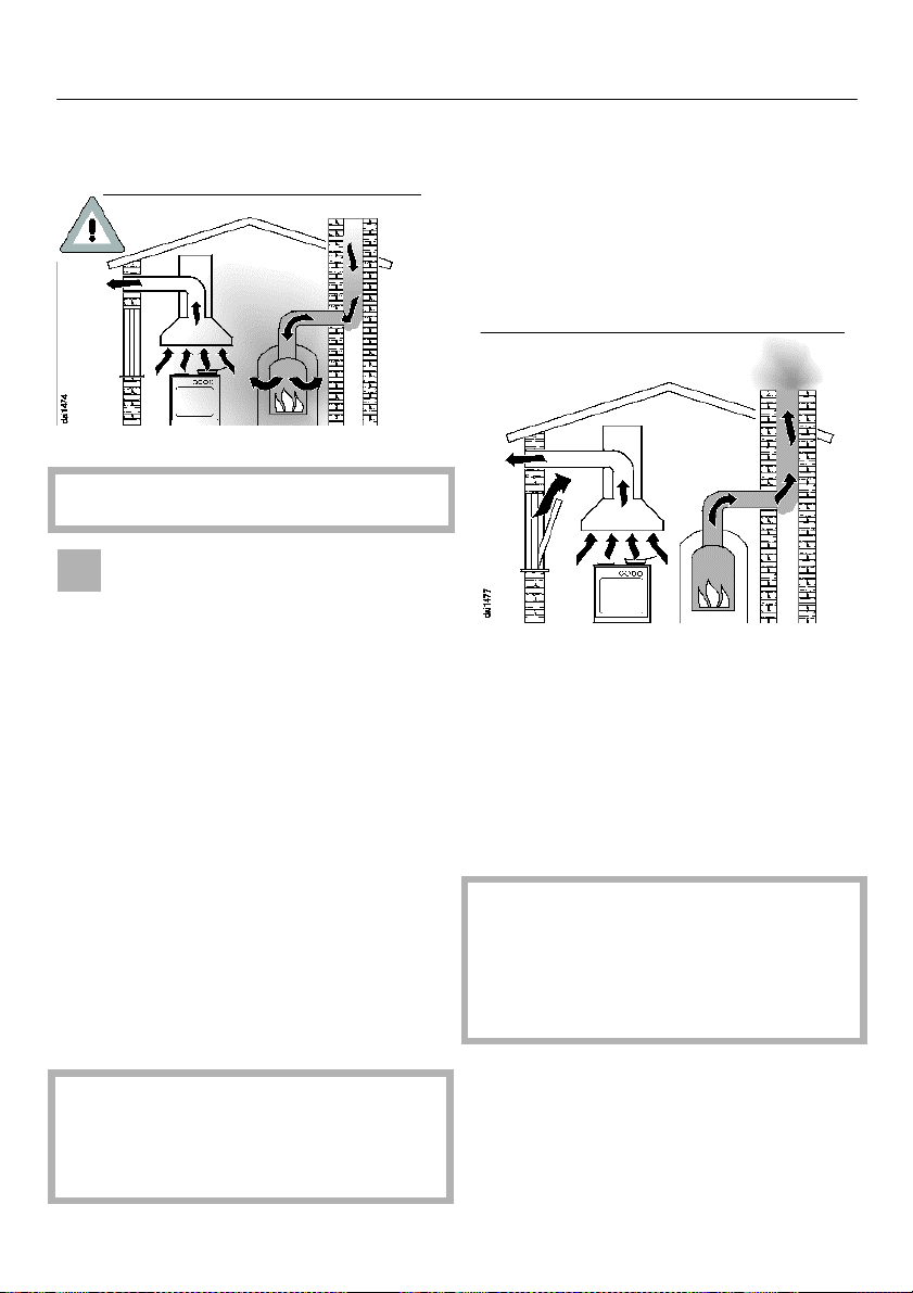
Using at the same time as other
heating appliances that depend on
the air from the room
Warning - danger of toxic fumes
Great care should be taken when
using the cooker hood at the same
time and in the same room or area of
the house as another heating appliance,
which depends on the air in the room.
Such appliances include gas, oil, wood
or coal-fired boilers and heaters,
continuous flow or other water heaters,
gas hobs, cookers or ovens which draw
air in from the room and duct exhaust
gases out through a chimney or
extraction ducting.
When used in extraction mode, with or
without an external motor, the appliance
draws air in from the room in which it is
installed and from neighboring rooms. If
there is insufficient air, an
Under pressure will occur. The heating
appliance may be starved of oxygen,
impairing combustion.
In order to ensure safe operation, and
to prevent gases given off by the
heating appliances from being drawn
back into the room when the extractor
and the heater are in operation
simultaneously, an under pressure in the
room of 0.04 mbar (4 pa) is the
maximum permissible.
Ventilation can be maintained by air
inlets, which cannot be blocked, in
windows, doors and outside wall vents,
or by other technical measures, such
as ensuring that the extractor can only
be switched on when the heating
appliance is switched off or vice-versa.
A ventilation brick alone is not generally
sufficient to ensure safe ventilation.
The overall ventilation condition of
the dwelling must be taken into
account. If in any doubt, the advice
of a competent builder or, for gas, a
"Corgi" installer, must be sought.
Harmful gases could be drawn out of
the chimney or extraction ducting
back into the room, with potentially
fatal consequences.
7
Warning and Safety instruction
Important: To avoid the danger of toxic
fumes please observe the Warning
and Safety instructions. This is
especially crucial when using the
cooker hood at the same time as
another heating appliance, which
relies on air from the same room. The
cooker hood should be installed
according to local and national
building regulations. Seek approval
from the building inspector where
necessary.
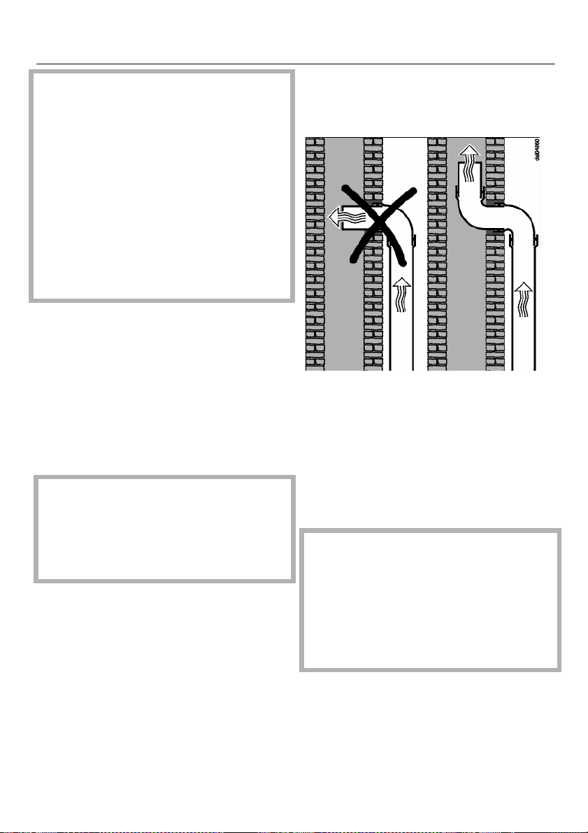
– All ducting, pipe work and fittings
must be of non-flammable materials.
– The exhaust ducting should be as
short and straight as possible.
– To ensure efficient air extraction, the
diameter of the exhaust ducting
should not be less than 125 mm.
If exhaust ducting with a diameter of
less than 150 mm, or if flat ducting is
used, the noise level of the cooker
hood will increase and extraction will
be less efficient.
Never reduce the diameter of the
ducting, e.g. where narrower ducting
has already been installed.
– Only use wide radius bends. Tight
bends reduce the air throughput of
the cooker hood.
– Only use smooth pipes or flexible
hoses made from non-flammable
materials for extraction connection.
– If the exhaust air is to be ducted into
a vent flue, the ducting must be
directed in the flow direction of the
flue.
Warning:
Luxair will not exchange or repair
damaged hoods caused by incorrect
ducting being fitted, the minimum
ducting must not be smaller than
125mm. never use ducting previously
installed from your last extractor unit.
8
Warning Ducted out hoods
Please take notice of the following
All Luxair cooker hoods must be fitted with 125mm-150mm ducting, this
must not be reduced in any way for the entire length of its run, it must also
not exceed 3.5mtrs in length from the top of the motor housing connection
to the outside vent plate (applies to all wall mounted and island models).
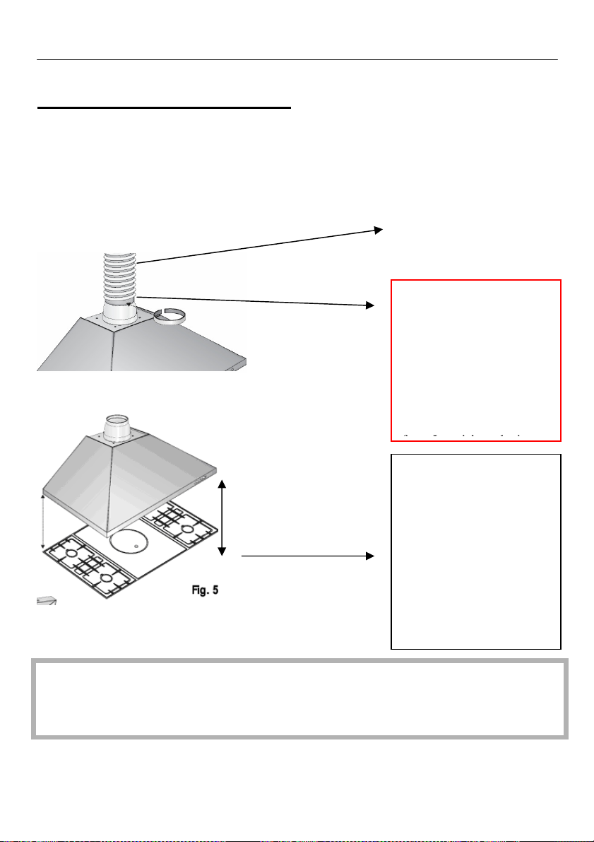
125 or 150 mm ducting
Ducting must be fitted to
the out-side of the
reducer collar and
secured with a zip
fastener, also the ducting
must be aluminium and
conform to fire
regulations.
Kits can be purchased
The minimum height
setting measuring from
the underside of the
extractor, to the top of the
gas hob is 750mm
And 650mm on electric
hobs, please note that
when using a hob larger
than 60cm please set the
minimum height to
750mm.
Warning:
Luxair will not cover the warranty if you have installed the cooker hood on either,
100mm ducting, or an old or existing ducting used by a previous appliance.
9
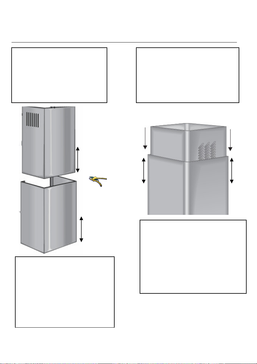
Cutting Down Chimney Sections
Luxair recommend that the
following procedure be carried out
by a qualified and competent
person, cutting the extended
chimney sections requires care and
should only be attempted by a
competent or qualified person.
Warning:
Luxair cannot be held liable for damage
caused by carelessness when modifying
the chimney sections; any modification
damage caused by modifying this
appliance is purely at your own risk.
Your statuary rights are not affected
100mm
It is recommended that the
maximum you can cut from the
chimney sections is 200mm, this
would be done as diagram above on
all wall mounted hoods, taking
100mm from the top section and
100mm from the bottom section
using Sharpe tin snips. Or electric
snipers.
100mm
10
When cutting down chimney sections
on Island hoods it is recommended that
the hood is taken to a professional
metal fabricator, they often have laser
cutting equipment that can make the
job easier, however if you attempt the
job directly then electric tin nibblers
should do the job. Follow instructions
opposite.
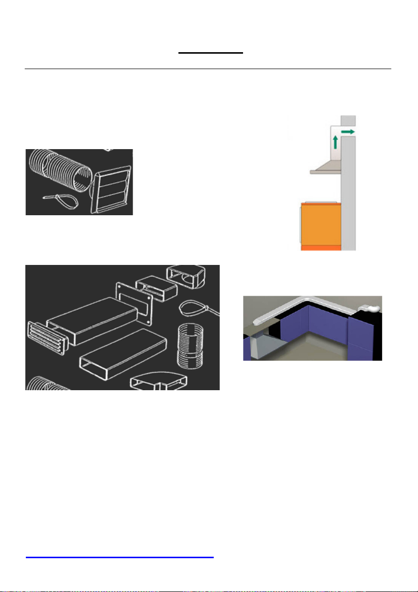
Ducting Kits
Fig 1
1.5 mtr Ducting kit
Fig 2
3.5 mtr Ducting kit
Ducting kits are used to vent you’re kitchen odors to the outside of the house, and we
recommend that only Luxair ducting kits are used with our products, this will also assure you
that the product’s warranty is not affected.
The 125mm system is designed to be used in conjunction with Cooker hoods and extraction
fans with a maximum output of 850m_ per hour.
All 125mm internal components are made from flame retardant Materials.
All wall outlets are UV stabilized. Please note that maximum extraction ducting length when
vented does not exceed 3.5mtrs on wall models and a max of 5.5 mtrs on island hoods.
NOT SURE THEN CALL VISIT OUR WEB SITE
WWW.LUXAIRHOODS.COM
Cooker hoods that are not to be vented to outside walls
Please note that if the hood is
not to be vented to an outside
wall, the top section of the hood
with the vents must be used,
this allows the filtered air back
into the room. Failure to do so
will result in the hood been
noisy and will cause it to
vibrate; this will also void the
warranty if this section is not
used when installed in
recirculation mode.
Note that when the hood is not
vented to an outside wall,
charcoal filters must be used in
conjunction with the above vent
system, image shows how to fit
the filters to a standard hood,
see page 21 and 23 for further
instructions and other models.
Fitting the filters on standard or round hoods is as follows.
Offer the round filter to the side of the motor housing, twist clockwise slowly
until you feel the filter sit, then twist clockwise until you feel it lock! Reverse the
process to remove. Please note that the charcoal filters will need replacing every
two months, failure to replace these filters will result in the warranty been void.
For replacement filters please visit our web site at
www.luxairhoods.com
12
Please Check the Following Points
1) Unpack the hood and inspect the goods carefully, please check for any cosmetic
damage before installation begins, Luxair will not accept liability for cosmetic
damage after the hood has been installed, if damage is found then please contact
the retailer from where the goods were purchased.
2) Check that all parts and fixings are packed in the box.
3) Do not remove any of the protective film until installation is complete, this will
help reduce any accidental damage and help prevent scratching.
4) Remove the metal Grease filters immediately after opening packaging and store
in a safe place, they will not be needed until installation is complete, this will
also ensure against accidental damage of the filters.
5) You must use either a ducting kit or charcoal filters with all Luxair hoods.
6) All filters and ducting kits can be purchased from our web
site.www.luxairhoods.com
13
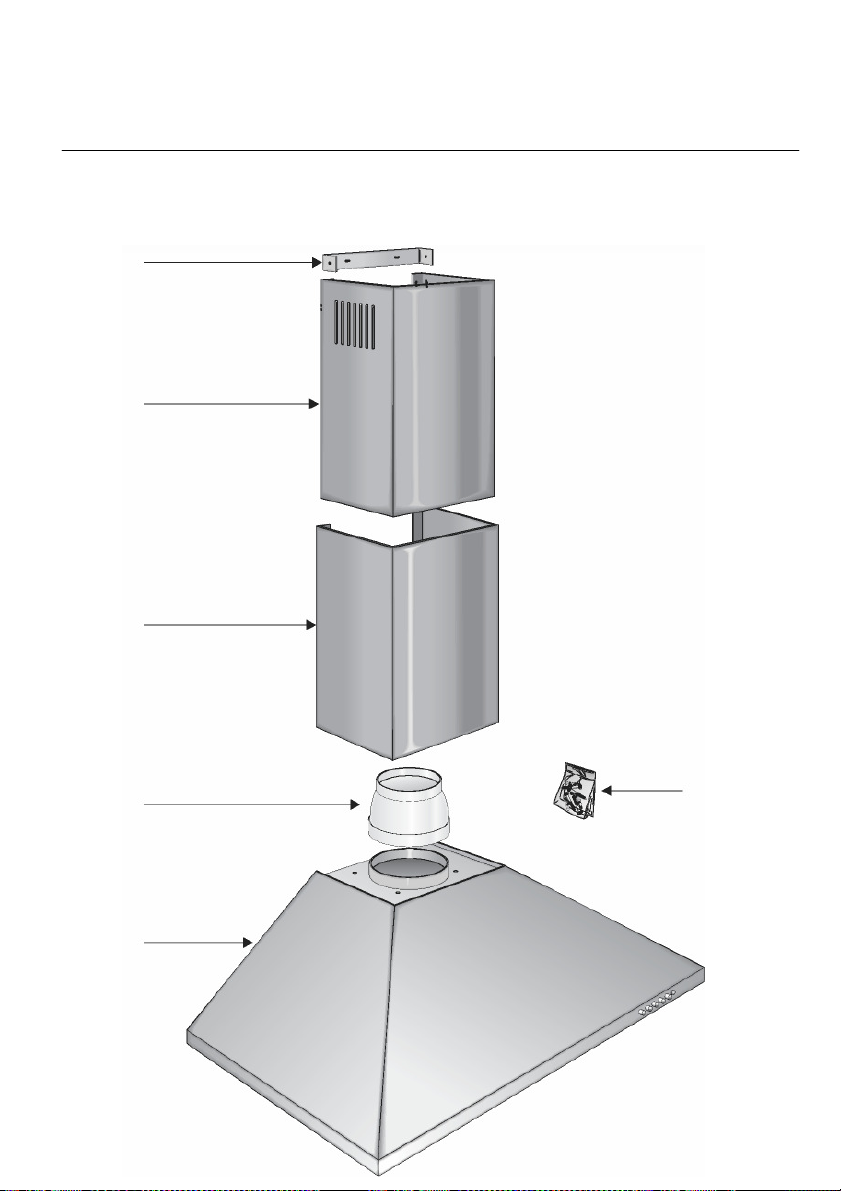
Standard Wall Mounted Hoods, STD, RND, OC
1
2
3
4 6
5
14

STD/RND Parts to the appliance
1 Wall Bracket
2 Top Chimney Section with Vents
3 Bottom Chimney Section
4 Reducer
5 Main Body
6 fixing screws
Press the button 1 to start the fan running on low, then increase to level 2 or
3 depending on cooking levels.
When the fan runs at power level 1. The indicator lamp will illuminate Red.
To select a power level
1-3 Use the numbered controls to select the power level required.
3 controls = higher setting 1 control = lower setting
Depending on the intensity of the cooking vapors, levels I to 2 are usually
sufficient for normal cooking.
•
Press the 0 control to switch the fan off.
The indicator lamp will go out.
15

advice.
Fitting Instructions Applies To All Wall Mounted Hoods
1
Position the cooker hood body
directly above your hob, make
sure that you comply with the
minimum height regulations set
out on page 10 and 12
2
Secure the main body of the
hood to the wall. Make sure
that the fixings are adequate for
the type of surface you are
fixing to.
Luxair provide some screws but
they may need changing
depending on the type of wall
you have, if you are in any
doubt then seek professional
3
Measure the desired height of
your chimney sections.
Measure the center of the main
body section of the hood and
then draw a straight vertical
line, place the metal u shaped
bracket at desired height center
to your line and secure the
bracket to the wall.
16

Fitting Instructions Applies To All Chimney Wall Hoods
4
Mark the height and position of your
ducting hole; this should be a
minimum distance from top o the
hood to the center of your hole
400mm, (see page 11).
Remove the hood of the wall before
drilling the ducting position; this will
stop any debris from falling into the
fan housing and avoid any damage.
5
Mark the height and position of your
fused spur socket position this so it’s
accessible, this should also be fused
with a 13amp fuse.
Remove the hood of the wall before
drilling for the electrics.
6
Remount the body section to the wall
and proceed to make all electrical and
ducting connections, make sure you
have complied with all safety
instructions as set out on page 3-11.
17

Warning
Fitting Instructions Apply To All Wall Mounted Hoods
7
Once all electrical and ducting has
being connected and tested proceed
to assemble the chimney sections,
place the bottom part of the
chimney into the body of the hood,
no fixings are required as the
grooves secure this part, slide the
top section into the bottom section
of the chimney, taking care not to
scratch this as you do so.
The vented top section can be
turned upside down if the hood is
ducted outside, this will hide the
vents that are unnecessary for
ducted out use. See page 12 for
more details on vented or
recirculated options.
18
8
Slide the top section into place over
the wall bracket, take care not to
scratch this as you do so, and secure
the top section to the bracket with
the two short screws provided.
Your new hood is now ready for
Do not attempt to clean down your
new hood until you have read the
cleaning instructions on pages 41
and 42. Careless cleaning could bur
and scratch your new hood.

Operation
Fitting The Charcoal Filters
9
If it was not possible to extract
you new hood to an outside
wall you must now fit this
cooker hood with charcoal
filters, failure to do so will void
the warranty, filters must be
changed at least every twothree months, this appliance
must not be used with out
filters if not ducted to an
outside wall. See page 10.
10
Metal grease filters are
designed to last the life of your
hood and can be purchase direct
from Luxair should they
become damaged. These filters
can be cleaned in your
dishwasher in the upright
position or by hand washing in
soapy hot water only.
11
Remove all the protective film
taking care not to damage your
new hood.
19

Curved Glass and Straight
Glass Wall Mounted Units
CVD-ST MODELS
1
2
3
4
5
6
20

CVD-ST Wall Mounted Models
1. Wall Bracket
2. Top Chimney Section
3. Bottom Chimney Section
4. Reducer Collar
5. Body Section
6. 8mm Safety Glass
7. Fixing Screws
Fitting the charcoal filter:
1
Remove the metal grease filter
to reveal the inner flue section.
2
Make sure all wires are pushed
to one side preventing
snagging.
3
Offer the filter to the bottom
and back the flue section and
insert into back L-shaped
Push the filter into place and
secure with the front screw as
opposite.
Please note that the filters are
only necessary for hoods that
are not vented to an outside
wall and must be replaced
every 50 hours or two- three
months.
21

Glass Wall Mounted Units.
Follow Fitting Instructions
1- 9 on Pages 18-20
1
After following instructions 1-9 on
pages 18-20 continue with this
section for the rest of the fitting of
this hood.
Once the hood is assembled and
checked, place your glass directly
on top of the main body section, line
up with the screw holes and secure
with screws and washers.
Warning: do not over tighten these
screws, they should be hand tight
only. Over tightening may cause the
glass to break.
2
After fitting the glass, now fit the
two telescopic chimney section,
please ensure that you do this with
care, slide the top section up to the
fixing bracket, and secure with the
two small screws in the fixing kit.
22

Operating your hood:
Electronic switches
1: select speed one to activate your fan, then
speed 2 and so on.
2: to turn on the lights press the light switch.
3: The T button is a timer switch, when
presses the T button will start to flash! This
means you have activated the timer unit, your
hood will turn its self of after 20mins, to cancel
this simply press the T button again.
4: if the light button starts to flash, simply
press and hold it for 5 seconds to deactivate
it.
1: select speed one to activate your fan, then
speed 2 and so on.
2: to turn on the lights press the light switch.
3: The clock button is a timer switch, when
presses the clock button will start to flash!
This means you have activated the timer unit,
your hood will turn its self of after 20mins, to
cancel this simply press the T button again.
4: you can turn off the led blue surround light
simply by pressing and holding speed 1, make
sure you have not activated the fan in order to
do this, to turn it back on simply repeat the
above process.
23

Octagonal Wall Units
Follow Fitting Instructions
1- 9 On Pages 18-20
24

Fitting the square filters
1
Remove the metal grease filter to reveal
the inner flu section.
2
Make sure all wires are pushed to one side
preventing snagging.
3
Offer the filter to the bottom and back the
flu section and insert into back L-shaped
bracket.
Secure the front of the filter using the
screw as diagram below.
25

Installation All Island Hoods
Please note: All Luxair Islands are
installed in exactly the same manner
and it is only the shape and design that
differ, please use the following steps for
all Island unit models.
Octagonal, Curved Glass,
Straight Glass, Oval And Black
26
Please note that the installation of all
Island hoods should be carried out
by at least two people.

Installation All Island Hoods
Ceiling
Ceiling
1
:
Position the inner top section of the
upper arm directly on the ceiling
and above your hob and mark the
center hole, also mark fixing
positions. Make sure you are center
to your hob.
2
:
Make sure that your fixings will hold
at least 75kg in weight; this must
also be flush with the ceiling. Drill a
150mm hole in the ceiling and
connect your ducting, run it to the
outside wall, this must not exceed
4mtrs in length.
3
:
Pass the ducting hose and electrical
cable through the center hole of the
top inner arm. Proceed to secure the
arm to your ceiling using either
coach screws (provided) or coach
bolts (not provided). It is paramount
that these fixings are strong enough
to hold the weight of the hood.
Warning:
All Island hood must be flush
mounted and under no
circumstances must the chimney be
inset into the ceiling void.
27

Installation All Island Hoods
4:
Before you go any further
assemble the glass (applicable
to glass units only) over the
main body of your hood and
secure with screws and
washers (provided).
Do not over tighten these
screws as you may cause the
glass to shatter.
5:
Insert the top stainless steel
chimney section into the bottom
stainless steel section; take care
not to force this as you may
cause damage.
28
6:
Lift the whole unit up onto the
main pre fixed upper inner arm,
slide it up or down to correct
height, make sure that you have
allowed the minimum height
above your hob unit.

page 42 and 43.
Installation All Island Hoods
7:
When you have selected the
correct height above your hob
secure the inner bottom section
of the flue, to the inner top
section of the flue in the fixing
positions as opposite. Your
cooker hood should now be
secure.
8:
Make all final ducting and
electrical connections through
the specially cutout hole. Test
that all ducting and electrical
connections are working before
completing the final part.
9:
Finally, lift the bottom outside
stainless steel section upwards,
(take care not to scratch this
section), and secure to the two
top mounting brackets with
screws (provided).
See cleaning instructions on
29

Changing The Bulbs
We at Luxair are constantly
modifying and upgrading our
products it is therefore
recommended you check your
appliance to identify the type of light
fittings installed.
Warning:
Please make sure that the
appliance is disconnected from
the mains supply before
carrying out any maintenance
work or cleaning. Never attempt
to remove the light fitting from
your hood as all bulbs are
replaced from the outside of
your hood, unless otherwise
advised.
Ball Lights
1 2
Removing the bulb, see fig 2:
Use a small screwdriver to remove
the black plastic ring from the face of
Light holder, once this is removed
the glass face will come lose, take
care not to drop this, remove the old
bulb and replace with 20w halogen 2
pin bulb. Do not touch the bulb with
your fingers as this may cause it to
fail, use a piece of tissue to insert
your new bulb.
Bulbs are not covered by warranty and can
be purchased from all major Diy stores or
your local electrical retailer.
30

Changing The Bulbs
Surface lights
Never try to remove the light fitting
from your hood, to remove the bulb
twist the metal ring anticlockwise,
the metal ring and the glass will fall
loose take care that you do not break
the glass, replace with a 20w halogen
bulb, never touch the bulb with your
fingers, use a tissue, replace the
glass and metal ring securing it in
the clockwise position.
When replacing a defective lamp
you should use exactly the same
type of bulb (see "Technical data"
for lamp specification).
Screw Bulbs
Remove the metal grease filters from
your hood to expose the light fitting
located at the back of your hood,(this
only applies to standard hoods)
Twist the bulb anticlockwise to
remove, replace with a 20/40 w max
screw bulb.
31

Before You Call Us
Below are a few checkpoints
you need to carry out before you
call us; unnecessary phone calls
can be avoided by checking
before you call, Please note that
Luxair cannot be held
responsible for incorrect
installation of the ducting
system, any problems relating to
this matter must be taken up
with the person or persons who
installed you hood.
1:
The most common calls are related
to vibration and noise, please check
the following to help you eliminate
this problem.
2:
Remove the chimney section to
your
Hood, revealing the connected
ducting system.
3:
outside of the plastic collar.
If the ducting is connected to the
inside of the collar this is incorrect
and must be replaced with 125mm
duct.
Luxair are not liable for incorrect
ducting or installation problems.
Check that the hose fits over the
32

Before You Call Us (Ducted Hoods)
4: To be 100% sure if the ducting is
causing the vibration and excess
noise levels disconnect it!
5:
After disconnecting the ducting
pipe via the collar (as above) switch
the cooker hood back on, has this
now stopped the vibration and
noise? If yes, then you need to
Debris from installation.
Check that the hood is correctly
mounted on the wall and has at least
four fixing screws.
Check for
debris in this
part of your
hood and that
the airflow is
clear.
contact the person who installed
your hood. Luxair are not
responsible for ducting problems.
6:
When all the above checks have
been carried out and you are still
experiencing vibration check that the
inner flaps at the top of the motor
housing are not obstructed by fallen
6:
Please note that extra noise
levels can be a problem when
the hood is mounted onto a
stud or partition wall, the
hollowness of these type of
walls echo the sound thus
increase noise levels.
33

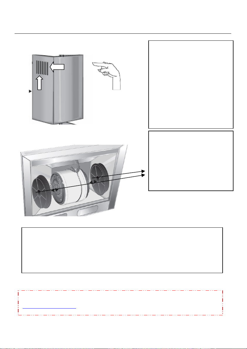
Before You Call Us (Non Ducted)
If your cooker hood is not ducted to
an outside wall and you are
experiencing vibration, then please
check the following.
The above chimney section must be
used when it is not possible to
extract to an outside wall, this is
necessary as the vents allow the air
flow back into the room, if this
section has not been used then
contact the person who installed
your hood and correct the problem.
Please note that in conjunction with
none ducted hoods; you must fit
charcoal filters in the hood, these
help to eliminate bad odors and
Make sure that the
top chimney with
vent section has
been installed on
all none ducted
hoods.
Purify the air; they also help to
prevent grease build up on the motor
fan blades.
Round
Charcoal filters
must be used with
all non-vented out
hoods.
Square
Please Note:
When using charcoal filters the
extraction rate will be 1/3 less
than ducted out hoods.
34

Before You Call Us (poor Extraction)
Poor extraction is caused by a
number of reasons, below are some
tips and hints to help eliminate such
problems.
Ducting can cause poor extraction if,
the ducting is run too far, over the
recommended 3.5mtrs. 5.5 mtrs on
island hoods
this can also add to vibration if the
vertical lift is higher than 2.5mtrs, air
becomes heavy and caused a down
fall or return, thus
Causing the motor to reverse and
vibrate.
If your ducting has too many bends
Pleas note:
Luxair install motors as stadered 650
cbm ph motors, in most domestic
installations this is suffice, however
we will provide at an extra cost a
higher exraction motor of 850 cmtr if
you require a higher extraction rate.
or elbows this can also cause poor
extraction rates, please note that
every time you use an elbow or bend
in the ducting run, you will lose up to
a third 1/3 of its extraction rate per
elbow. Try to avoid too many bends.
This will not include the cost of
installation and will be charged as an
extra. For advise please call our
sales advise team on further
information.
35

Before You Call Us (poor Extraction)
Turn the hood on at speed 1, Take an
A4 piece of paper and place it flat on
your hand, then offer it up to the
metal grease filters, place the paper
Up against the filters and remove
your hand, the paper should stay in
place, if it does not then you need to
check the ducting or call the person
who installed the hood.
Never install Luxair hoods with
ducting smaller than 125mm, if you
are replacing an existing extractor,
never use the old ducting system
previously installed, they are more
often than not only 100mm in size
and cold be damaged your new
hood, they are also unlikely to be
flame retardant. This will also cause
problems not only with extraction,
but also with vibration.
Cooker hoods will only remove 60%
of the steam or vapors when
Cooking, they do not extract all
Vapors the minute the extractor is
Turned on, a vortex is created in the
room thus allowing it to clear all
vapors usually within one hour.
Before calling us, please take note of
the points set out in this manual, if
you are in any doubt then please
seek professional qualified
assistance.
36

Before You Call Us (Remote units)
Remote Control Hoods
1: stand 6-10 feet from your
chimney hood and point the remote
at the chimney section of the hood.
2: to operate the lights press the first
blue button, lights on, press again
lights off
3: to operate the motor, press the
second blue button (top right) this
will operate speed one only.
4: To operate speed 2, press the third
blue button once (bottom right).
5: To operate speed 3, press the
same blue button once again, this
will operate speed three.
Please note: that the red indicator
light at the top right hand corner
should illuminate at each press of
any button, if this dose not
illuminate then you should replace
the battery.
6:To replace the battery clip the
back cover off, remove old battery
and replace with a 12v alkaline
battery only. Please also note that
batteries are not covered by warranty
and may need changing even if the
unit is new.
warning
Please note: Remote control hoods are
not suitable for all areas as they are
operated by Microwaves, the operation
of your hood can be affected in areas
where there are high levels of
Microwaves, i.e. near Airports, Police
stations or any environment that has
high microwave activity. Luxair cannot
be held liable for units that are affected
by this. If in doubt seek advice.
37

Luxair Help Line UK
We at Luxair are here to help, if you
need any assistance or advise on
installing your new hood, please call
our UK help line.
Help line
0044 (0) 1765 641888
Fax Us
0044 (0) 1765 641889
E mail
info@luxairhoods.com
Web
www.luxairhoods.co.uk
www.luxairhoods.com
All calls are charged at local rate:
NOTES:………………………………
…………………………………………
…………………………………………
…………………………………………
…………………………………………
…………………………………………
…………………………………………
…………………………………………
…………………………………………
…………………………………………
…………………………………………
…………………………………………
…………………………………………
…………………………………………
…………………………………………
…………………………………………
…………………………………………
…………………………………………
…………………………………………
…………………………………………
…………………………………………
…………………………………………
…………………………………………
…………………………………………
…………………………………………
38

Cleaning And Care
Before carrying out any cleaning or
maintenance work, disconnect the
cooker hood from the mains supply.
Ensure that:
– it is switched off at the wall socket
and the plug withdrawn, or
– the fuse is withdrawn from the
fused spur connection unit, or
– the mains fuse is withdrawn, or
– the screw-out fuse is removed (in
countries where this is applicable).
General notes
The surfaces and controls are
susceptible to scratches and
abrasions. Please observe the
following cleaning instructions.
• All external surfaces and controls can
be cleaned using a Luxair E-Cloth, or
wit h w arm wa ter a nd a lit t le
washing-up liquid applied with a well
wrung-out soft sponge or cloth.
• Wipe the surfaces dry using a soft cloth.
–
– Abrasive cleaning agents e.g.
powder cleaners or cream cleaners,
and abrasive sponges, e.g. pot
scourers or sponges which have
been previously used with abrasive
cleaning agents. These will damage
the surface material.
Important for appliances with
stainless steel housing
(This information does not apply to the
controls).
Stainless steel surfaces can be cleaned
using the Luxair E-Cloth, or with a
proprietary non-abrasive cleaning
agent designed specifically for use on
stainless steel.
To help prevent re-soiling, a proprietary
conditioning agent for stainless steel
such as baby oil or olive oil can also be
used. Follow the manufacturer's
instructions, and apply sparingly with
an even pressure in the direction of the
"grain".
Controls
Do not use too much water when
cleaning the controls. Water could
penetrate into the electronics and
cause damage.
Do not use:
– Cleaning agents containing soda,
acids, chlorides or solvents,
The controls may suffer discoloration
or damage if soiling is left on them for
too long.
Remove soiling straight away.
Never spray cleaning products
directly at the control or switch
panels.
39

Please observe the General notes on
cleaning.
Do not use stainless steel cleaning
agents on the controls.
Glass surfaces
Glass surfaces can be cleaned using a
proprietary non-abrasive cleaning
agent designed specifically for use on
glass.
Avoid oven sprays.
To avoid damaging the filter or the
hob below, make sure you hold the
filter securely at all times when
handling it.
To remove the Grease Filter.
Pull the plate down towards you at
the top, push the bottom slightly to
the right and pull forwards to remove
(see illustration).
Cleaning the grease filter by hand
• Clean the filter with a soft nylon brush
in a mild solution of hot water and a
little washing-up liquid.
Do not use "neat" washing up liquid.
Do not use:
– Cleaning agents containing
descaling agents,
– Alkaline cleaning agents (with a pH
value higher than 7), such as powder
cleaners, cream cleaners or abrasive
all-purpose cleaning agents,
– Oven sprays.
Cleaning the grease filter in the
dishwasher
• Place the filter with the short side
upright in the lower basket, and wash
on a 65° programme using a mild
Dishwasher detergent; ensuring the
spray arm is not obstructed.
Avoid alkaline dishwasher detergents
(with a pH value higher than 7).
Depending on the cleaning agent
used, cleaning the filter in a
dishwasher can cause permanent
discoloration to the surface.
However, this will not affect the
functioning of the filter in any way.
• After cleaning, leave the filter to dry
for a while on an absorbent surface
before putting it back in place.
40

Luxair Hood Size Charts
The following size chart shows all
cooker hoods sizes as they are
packed in there boxes from our
factory, however they can be cut
down to a lower height if required,
please take great care if you
attempt this and please refer to
pages 10 for further instructions on
this procedure.
Luxair cannot be held liable for
damage caused by cutting or
altering the above standard heights,
cutting or altering the above hoods
is done so at your own risk.
Should you require replacement
parts due to damage please call our
help line on page 40.
MAX
STD HOOD
1020mm
MIN
STD HOOD
790mm
41

Electrical Connections
All electrical work should be
undertaken by a suitably qualified
and competent person in strict
accordance with current national
and local safety regulations
(BS 7671 in the UK).
Installation, repairs and other work by
unqualified persons could be
dangerous, for which the
manufacturer cannot be held liable.
Ensure power is switched off to the
appliance until after installation or
repair work has been carried out.
Do not connect the appliance to the
mains electricity supply by an
extension lead. These do not
guarantee the required safety of the
appliance.
When switched off there must be an
all-pole contact gap of 3 mm in the
switch (including switch, fuses and
relays according to EN 60335).
If the switch is not accessible after
installation (depending on country), an
additional means of disconnection must
Be provided for all poles.
For extra safety it is advisable to
install a residual current device (RCD)
with a trip current of 30 AMP.
Important
U.K., IRL, NZ, ZA: This appliance is
supplied for connection to an a.c.
230 V single phase 50 Hz supply.
AUS: This appliance is supplied for
connection to an a.c. single phase
240 V, 50 Hz supply.
The connection data is given on the
data plate. This is visible when the
grease filters have been removed.
Ensure that this data matches the
household mains supply.
Connection of this appliance should be
made via a suitable isolator or a double
pole fused spur connection unit which
complies with national and local safety
regulations and the On-Off switch
should be easily accessible after the
appliance has been built in.
42
The wires in the mains lead are
colored in accordance with the
following code:
Blue = neutral
Brown = live
This appliance is double insulated

Technical data
Total connected load* . . . . . . . . . 240 W
− Fan motor*. . . . . . . . . . . . . . . . . 200 W
− Hood lighting . . . . . . . . . . . . ..2 x 20W
Halogen lamps
Osram type 44888 WFL, 20 W
Voltage
UK, NZ, ZA . . . . . . . . . . . . . . .AC 230 V
AUS . . . . . . . . . . . . . . . . . . . .AC 240 V
Frequency . . . . . . . . . . . . . . . . . .50 Hz
Fuse rating (UK). . . . . . . . . . . . . . 13A
AUS, NZ:
Plug rating . . . . . . . . . . . . . . . . . . .13 A
Test marks . . . . . . . . . .Electrical safety
. . . . . . . . . . . . . . . . . . . . .. C-Tick Mark
Electrically suppressed
according to AS/NZS 1044
Electrical cable length . . . . . . . 1.5 mtr
Decibel ratings
Noise Level Min/Max (CBM/H)
applies to wall mounted hoods
Speed 1 =
37.5DB
Speed 2 =
46.9DB
Speed 3 =
56.9DB
Fan performance wall mounted
hoods
Extraction power according to
EN 61591
Extraction system 0 150 mm:
Level I . . . . . . . . . . . . . . . . . . .200 m3/h
Level II. . . . . . . . . . . . . . . . . . .300 m3/h
Level III . . . . . . . . . . . . . . . . . . 650 m3/h
Extraction system 0 125 mm:
Level I . . . . . . . . . . . . . . . . . . .180 m3/h
Level II. . . . . . . . . . . . . . . . . . .280 m3/h
Level III . . . . . . . . . . . . . . . . . . 550 m3/h
Unrestricted . . . . . . . . . . . . . . .680 m3/h
* For EXT models, the connected load
and extraction power will depend on
the type of external motor fitted.
EXT models:
Length of connection cable to external
motor . . . . . . . . . . . . . . . . . . . . . . .1.9 m
Fan performance Island Hoods
Extraction system 0 125 mm:
Level I . . . . . . . . . . . . . . . . . . .280 m3/h
Level II. . . . . . . . . . . . . . . . . . .380 m3/h
Level III . . . . . . . . . . . . . . . . . . 800 m3/h
Unrestricted . . . . . . . . . . . . . . .890 m3/h
43

WARRANTY FORM
---------------------------------------------------------------------------------------------------------------
Name:
*
Contact Name:
Phone Number:
Mobile Number:
Email Address:
*
*
*
*
Postal Address:
---------------------------------------------------------------------------------------------------------------
HOUSE NAME OR NUMBER:
ADDRESS:
TOWN OR CITY:
---------------------------------------------------------------------------------------------------------------
Serial Number:
Model Number:
*
*
Postcode *
*
*
Please note: this box must have the correct serial number and model number in order
To activate your warranty, this form must also be returned to Luxair within 31days
After installation.
Purchase Details:
--------------------------------------------------------------------------------------------
Purchased From:
Date Purchased:
See back page for address details.
*
*

Alteration rights reserved / 1306
Nr. 06 783 600 / 02
Lux Air Policy
Lux Air operates a policy of continuous improvement and reserves the right to adjust and modify its
products and prices without prior notification. All the Operational Extra Kits can be purchased if required
PLEASE NOTE: All ducted out hoods must use a five-inch (5") ducting, failure to do so will result
in the warranty being void. In addition, all hoods must be surface mounted and free from
obstructions.
The information is provided on the understanding that the website is not engaged in rendering legal
advice. Further more no liability can be accepted for loss or expense as a result of using this website. By
using the Website you agree that in no circumstance shall The Company be liable for any indirect,
incidental, special or consequential damages, including, but not limited to, loss of business or profits or
any other financial loss, arising out of or in any way connected with the use of the Website, under any
law or on any basis whatsoever whether contractual or otherwise.
Luxair will not accept returned goods for credit if purchased by you in error, we will refund in full or
replace damaged or faulty goods only if installation has not taken place, goods that have been installed
and found to be faulty must be treated as a service call and it is up to you the purchaser to instigate the
service call Goods damaged by incorrect installation procedures or by an unqualified electrician will not
be exchanged or replaced however spares can be purchased at an additional cost to you to help rectify
the situation.
Service call check list Before calling our service departments please ensure that the following checks
have been done: 1, all electrical connections have been installed by a qualified electrician and that a
fused spur has been installed for safety. 2, ducting used must be 125mm minimum, filters and
accessories have been installed correctly as per the instruction manual. 3, please note if the appliance is
found to be a faulty or inadequate installation you will be charged for the call out and parts needed to
rectify the problem. Your statutory rights are not affected.
The information is available on the Website are provided on an "as is" basis without any representations
or endorsements made and without any warranty of any kind whether express or implied, including but
not limited to implied warranties of fitness for purpose, merchantability and accuracy.
Nothing contained in the Website is intended to constitute legal advice of any sort, and the basis on
which you acquire or make use of any information or document is that the information or technical advise
is suitable for use by you in conjunction with proper advice as to its application and adaptation for your
particular requirements. We will not have any liability to you at all if you use any information or advise
without obtaining appropriate legal advice nor will we have any responsibility at all for any alterations
made to the appliance after you have received it.
Your statutory rights are not affected.
M.-
en - GB

Alteration rights reserved / 1306
Nr. 06 783 600 / 02
.
Lux Air UK,
Lux Air House,
Unit 2 & 5, Keld Close
Barker Business Park,
Melmerby,
Ripon
North Yorkshire
HG4 5NB
Telephone: OO44 (0) 1765 641888
Fax: 0044 (0)1765 641889
Help Line
Email: info@luxairhoods.com
Web: www.luxairhoods.com
0044 (0) 1765 641888
M.-
en - GB
 Loading...