

Page 1
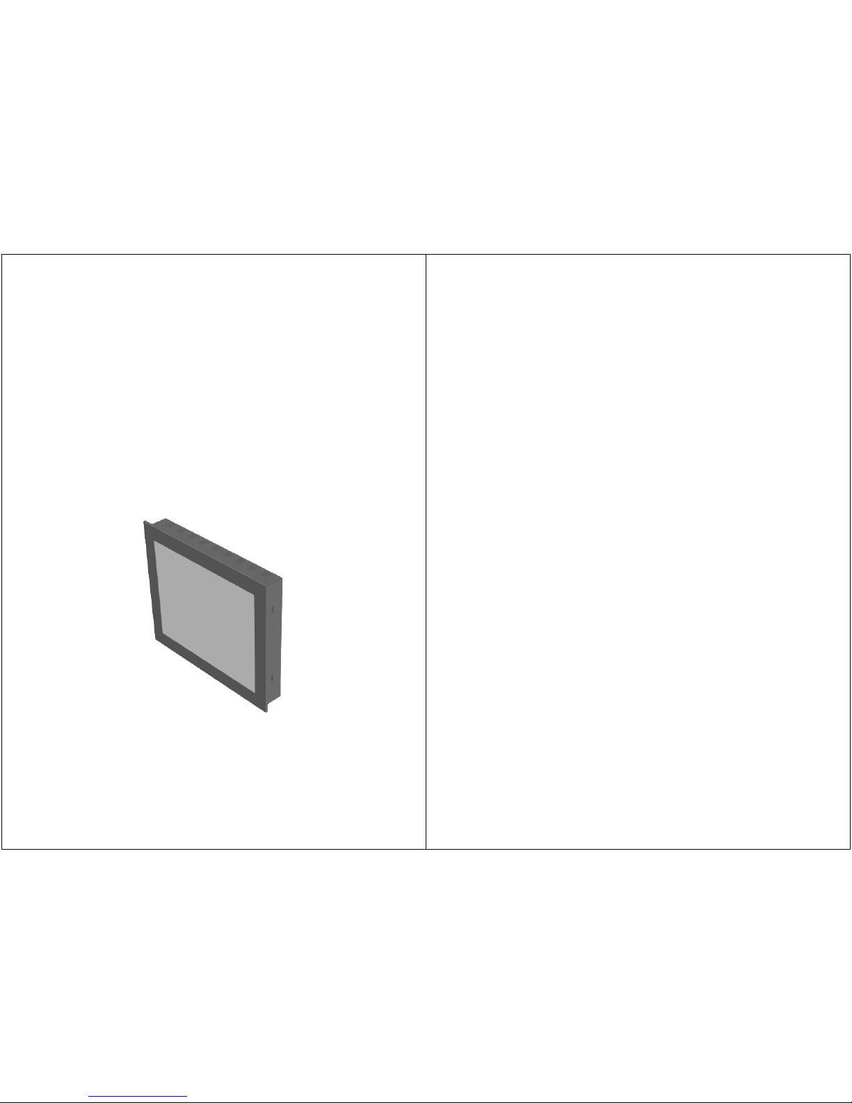
LUVOX
LCD MONITORS
ALL-IN-ONE SYSTEMS
INFORMATION GUIDE
REVISION 0.08 - JV April 27, 2010
- 1 -
Menu
1. Important Information ········································Page.2
Important Safety Instructions······························Page.2
Contact Information ··········································· Page.2
2. Introduction ·······················································Page.3
Description ·······················································Page.3
Standard Package Content ·································· Page.3
Standard Product Features ··································Page.4
Cleaning ···························································Page.5
Precautions ·······················································Page.5
3. LCD monitor Control Functions ·····························Page.6
Key functions ····················································Page.6
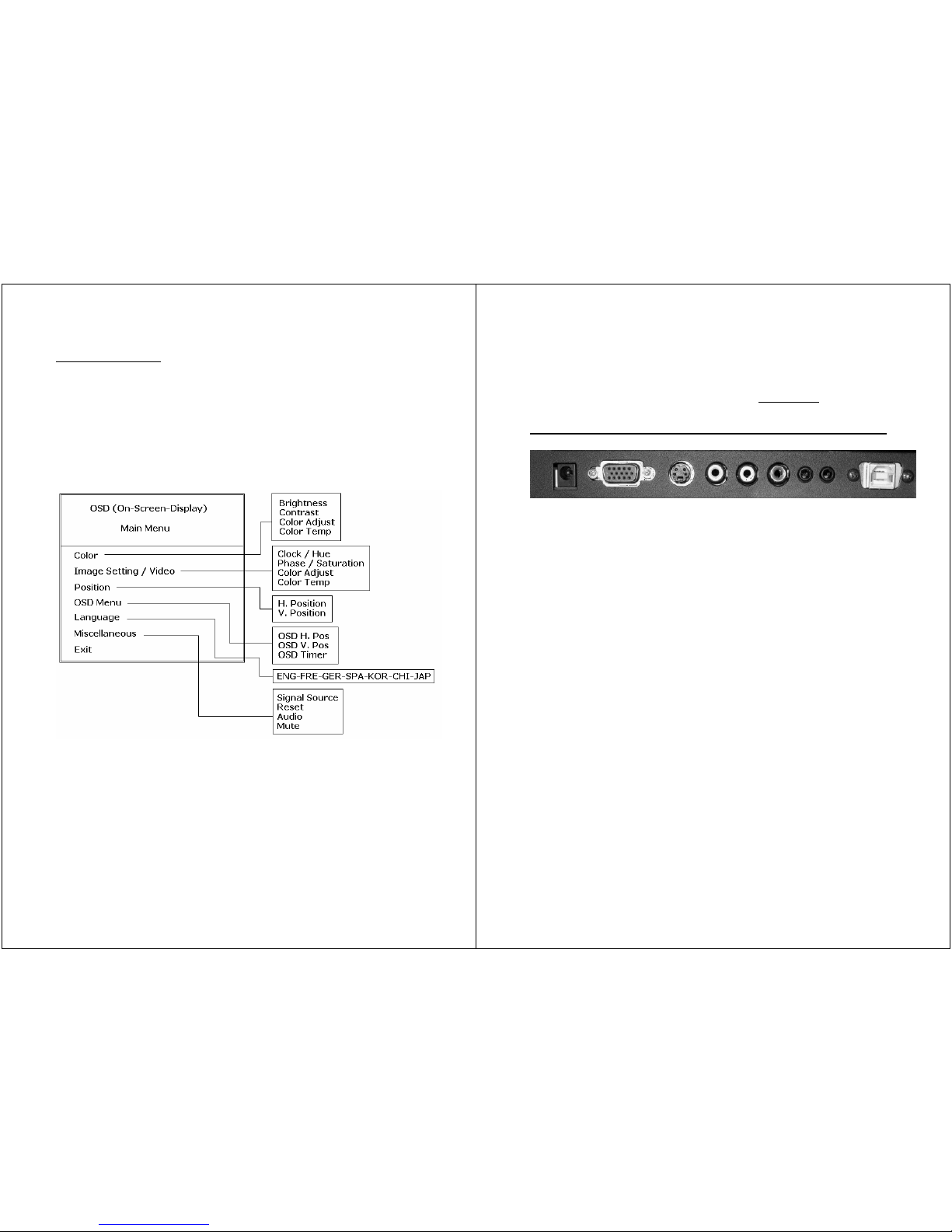
OSD functions ···················································Page.7
OSD overview ···················································Page.10
4. LCD Monitor Setup ·············································· Page.11
Connector layout ···············································Page.11
Driver installation ··············································Page.12
Touch Alignment (Calibration) ·····························Page.13
5. LCD Monitor Product Specifications ························ Page.14
6. All-In-One systems ·············································· Page.16
Description ·······················································Page.16
Connector layout ···············································Page.17
Accessing main board area··································Page.18
AIO (default) BIOS settings·································Page.19
Storage setups ·················································· Page.23
7. LUVOX Panel Mount Installation·····························Page.25
Securing with Front Mount Brackets ····················· Page.25
Securing with Side Skirt Bolts······························Page.26
8. LUVOX optional features ·······································Page.32
ProLine ····························································· Page.32
IP65 front ·························································Page.34
Rack Mount Bezel ·············································· Page.40
Rear Mount Brackets ·········································· Page.43
9. LUVOX Product Identification·································Page.50
10. LUVOX Service Information ·································Page.53
Appendix: LUVOX Dimensional Drawings ····················Page.54
Page 2
- 2 -
Important Information
Important Safety Instructions
Caution
: To prevent electric shock, please do not remove any
covers or any internal components. Refer to a qualified technician
for service.
Caution
: Unplug the device from the power outlet before
cleaning. Use a soft damp cloth.
Caution
: Please follow the national guidelines for unit disposal.
Contact Information
:
DOBIT NV - Belgium
TEL: +32 (0)14 285 785
FAX: +32 (0)14 219 811
Industrielaan, 6
B-2250 Olen
Belgium
DOBIT BV - Holland
TEL: +31 (0)492 472 638
FAX: +31 (0)492 472 668
Steenovenweg, 5
5708 HN Helmond
The Netherlands
www.dobit.com
[email protected]
[email protected]
- 3 -
Introduction
Description
Congratulations on the purchase of your new LUVOX device. Each
LUVOX professional LCD monitor or All-In-One system features a
color active matrix thin-film-transistor (TFT) liquid crystal display
to provide superior display performance with resolutions from
VGA 640x480 to SXGA 1280X1024. Each LUVOX device can be
optionally equipped with a wide range of ELO touch technologies.
The LUVOX product range represents a family of all-steel chassis,
rugged design, industrial LCD flat panel devices.
Standard LUVOX Package Content
Included with a standard LUVOX LCD monitor:
• LUVOX LCD monitor
• 15pin D-sub signal cable (VGA cable)
• Composite video & audio cable
• S-video cable
• AC power cable
• Power adapter (40W minimum)
• USB and/or RS232 touch interface cable (optional)
• ELO drivers CD-ROM (optional)
• Front mount brackets
• Screw set (4xM4x30, 4xM4x12, 8xM3x6)
Included with a standard LUVOX all-in-one system:
• LUVOX All-in-one system
• AC power cable
• Power adapter (60W minimum)
• Driver CD-ROM(s)
• Front mount brackets
• Screw set (4xM4x30, 4xM4x12, 8xM3x6)
• Additional model dependent accessories
Page 3

- 4 -
Standard Product Features
Standard LUVOX LCD monitor
• 16M High contrast colors up to SXGA 1280X1024.
• Compatible with VESA standard and DDC1/DDC2B
• VGA, audio, composite video, S-Video signal inputs
• OSD and auto-color & -tracking control
• Display Power Management Signaling (VESA PDMS)
• Touch screen interface (optional)
• VESA 75/100mm Mounting
• Integrated 4 Watt Stereo amplifier for kiosk purpose
• All-steel rugged design
standard LUVOX All-In-One system
• 16M High contrast colors up to SXGA 1280X1024
• Integrated Socket 478 industrial MINI-ITX board
• Intel Pentium® M or Celeron® M based platform
• 400MHz FSB
• DDR SDRAM 200/266/333 MAX 1GB
• 10/100 Base-TX Ethernet, 4x USB 2.0, AC97
• 2x RS232, 1x Parallel port, 1x 1394, PS/2, Audio
• Type II True IDE Mode CF Socket(s) (optional)
• Touch screen operation
• VESA 75/100mm Mounting
• All-steel rugged design
More detailed information about the integrated MINI-ITX
embedded board can be found in the installation guide which is
delivered as documentation with your LUVOX all-in-one system.
More detailed information about ELO and the optionally integrated
touch screen technologies can be found on the ELO website:
www.elotouch.com
- 5 -
Cleaning
• Clean with a soft damp cloth
• Use non-ammonia glass cleaners
Precautions
• Read instructions carefully
• Opening or removing covers may expose you to dangerous
shock hazards or other risks.
• Handle with care when transporting and save packaging
• Do not block vent holes. Do not insert sharp objects or spill
liquid into the device. They may cause accidental fire, electric
shock, or failure.
• Do not attempt to service this product yourself.
• Do not remove the ground prong from the adapter or the AC
power plug.
• Do not disconnect any cables from a device in operation
• Make sure power source voltages are correct when not using
the standard power adapters.
• Place the device in a ventilated place.
• Ensure that sufficient space is available around the device to
provide air circulation.
• Keep the monitor away from extreme heat, cold, humid or
dusty environments. Avoid direct sunlight and equipment that
generate magnetic fields.
• If the equipment is not used for a long time, disconnect it
from the power source.
Page 4
- 6 -
LCD Monitor Control Functions
(Chapter applies to standard LUVOX LCD MONITORS Only)
Each LUVOX LCD monitor has an internal microprocessor
dedicated to control display image. This microprocessor has the
capability to adjust the monitor to the source it is attached to.
This auto-adjustment is done when the unit is first installed,
connected and powered up, and each time the video input source
is changed. When the display image is not satisfying, the user can
adjust all settings by entering the OSD (On-Screen-Display) menu
functions with the control keys located on the backside of the
monitor.
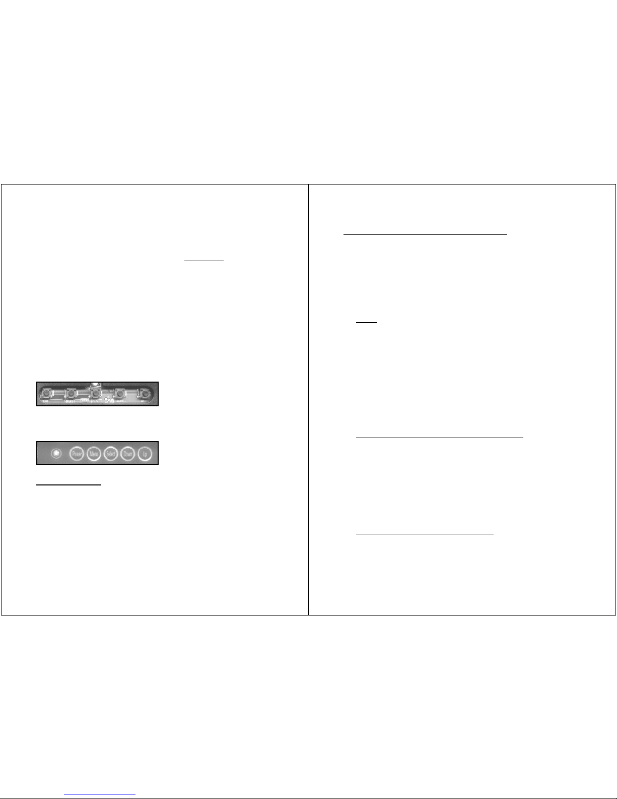
LUVOX F100 & F120 LCD monitor series control keys:
(menu – select – power – down – up)
LUVOX F150, F170 & F190 LCD monitor series control keys:
(power – menu – select – down – up)
Key functions
1. Press POWER to turn on the monitor (power LED indicates
green), press POWER again to turn it off.
2. Press SELECT to select input source:
VGA <select> Composite Video <select> S-Video
(power LED indicates red for invalid signal sources)
3. Press UP to run the AUTO-COLOR balance function
4. Press DOWN to run the AUTO-ADJUST image function
(AUTO- functions are only possible in VGA mode)
- 7 -
OSD (On-Screen-Display) function
1. Press MENU to activate the OSD menu
2. Press UP / DOWN to navigate between the primary
functions.
3. Press SELECT to enter one of the primary functions
4. Press MENU to return one level in the menu
5. Press MENU in the main menu to exit OSD and save all
settings in memory.
Color
1. In the main menu select COLOR.
2. Press UP / DOWN to navigate
3. Press SELECT to adjust value with UP / DOWN
4. return to previous level with MENU
Brightness: Adjust intensity level of the image
Contrast: Adjust bright / dark level difference
Color Adjust: Adjust color of the screen’s image
Color Temp: 9300 and 6500 temperature setting
& RGB adjustable user temperature
Image Setting (2nd function in VGA mode)
1. In the main menu select IMAGE SETTING.
2. Press UP / DOWN to navigate
3. Press SELECT to adjust value with UP / DOWN
4. return to previous level with MENU
Clock: Adjust horizontal size of the image
Phase: Adjust focus of the image
Sharpness: Adjust clarity of the image
Video (2
nd
function in video mode)
1. In the main menu select VIDEO.
2. Press UP / DOWN to navigate
3. Press SELECT to adjust value with UP / DOWN
Page 5

- 8 -
4. return to previous level with MENU
Hue: Adjusts NTSC phase (NTSC only)
Saturation: Adjusts color level (NTSC & PAL)
Sharpness: Calibrate image focus (NTSC & PAL)
Position
1. In the main menu select POSITION
2. Press UP / DOWN to navigate
3. Press SELECT to adjust value with UP / DOWN
4. return to previous level with MENU
H. Position: Adjust horizontal position of the image
V. Position: Adjust vertical position of the image
(H. Position & V. Position have no effect in video mode)
OSD Menu
1. In the main menu select OSD MENU
2. Press UP / DOWN to navigate
3. Press SELECT to adjust value with UP / DOWN
4. return to previous level with MENU
OSD H. Pos: Adjust the horizontal position of OSD
OSD V. Pos: Adjust the vertical position of OSD
OSD Timer: Adjust OSD closing time when no actions
Language
1. In the main menu select LANGUAGE
2. Press UP / DOWN to navigate
3. Press SELECT to adjust value with UP / DOWN
4. return to previous level with MENU
Language: Select desired OSD language
- 9 -
Miscellaneous
1. In the main menu select MISCELANNEOUS
2. Press UP / DOWN to navigate
3. Press SELECT to adjust value with UP / DOWN
4. return to previous level with MENU
Signal Source: Select default input signal source
Reset: Returns all controls to factory settings
Audio: Adjust volume of internal amplifier
Mute: Toggle internal amplifier ON/OFF
Exit
Exit OSD menu
(Press SELECT only once. Otherwise the display mode will be
switched to the next input source)
Page 6
- 10 -
OSD Overview
- 11 -
LCD Monitor Setup
(Chapter applies to standard LUVOX LCD MONITORS Only)
connector layout (standard LUVOX LCD Monitor)
1. DC POWER INPUT: DC 12V jack (center pin +)
2. VGA: This can be connected with the D-Sub 15-pin connector
of any analog VGA RGB source
3. S-VIDEO IN: This can be connected to the S-Video connector
of any video source.
4. VIDEO IN: This can be connected to the RCA connector of
any video source.
5. RCA audio LEFT: left RCA audio input can be connected to
any RCA sound source
6. RCA audio RIGHT: right RCA audio input can be connected to
any RCA sound source
7. LINE IN: this input can be connected to any stereo source
(e.g. a PC sound card).
8. AUDIO OUT: this output can be directly connected to audio
speakers or headphones
9. USB or RS232 port (for touch monitors only): ports to be
connected to your PC for touch functionality.
NOTE: LUVOX professional monitors have a broad range of
optional features available. This means your monitor could have
extra connectors available for different purpose.
Page 7

- 12 -
Driver installation
Each LUVOX device can be equipped with an ELO touch screen.
The 4 ELO touch technologies adapted in LUVOX devices are:
• ACCUTOUCH (5-wire resistive)
• CARROLLTOUCH (Infrared)
• INTELLITOUCH (Surface acoustic wave)
• SURFACE CAPACITVE (only produced on project basis)
Visit the ELOTOUCH corporate website for more information about
each available technology.
www.elotouch.com/Technologies/default.asp
Each LUVOX LCD monitor powered with an ELO touch screen
comes with an ELO driver CD-ROM in the accessory box. You will
need to install this driver CD-ROM before the monitor becomes
fully functional. Please insert the CD-ROM and follow the
instructions on the screen. After you have installed the driver, you
will be automatically asked to calibrate your monitor. Afterwards,
your monitor is ready to use.
If the driver CD-ROM is lost, damaged or out of date (Cfr use with
WINDOWS VISTA), you can download the latest driver version
from the ELOTOUCH website. Select the correct driver based on
your operating system and touch technology.
www.elotouch.com/Support/Downloads/dnld.asp
- 13 -
Touch Alignment (Calibration)
The touch response must be aligned to the video image (this is
called calibration). Normally this is done when the touch drivers
are initially installed. But in some conditions re-calibration may be
needed, for example after swapping or replacing monitors on the
same machine.
On regular Windows systems the Alignment/Calibration utility is
run from the Control Panel. This calibration procedure is also valid
on a LUVOX All-In-One system.
• Click the Start button.
• Select Settings, then Control Panel (on later operating
systems the Settings step is omitted)
• Open the Elo applet by double-clicking the Elo icon.
• On Windows XP it may be necessary to click the Show Classic
View button to see the Elo icon.
• The Alignment/Calibration button is always on the General tab
of the Elo Control Panel tab set
• Click the button, touch target in the upper left corner.
• The target will reappear in the lower right corner
• Touch the upper right target.
• The next screen is an alignment check. Touch various
positions and check the cursor movement.
• Clicking the redo arrow icon will display the targets again to
rerun the alignment routine.
• You must click the Accept button to store the new alignment
points.
NOTE: You may find other interesting features in the ELO control
panel regarding sounds, right mouse click emulation, etc…
Page 8
- 14 -
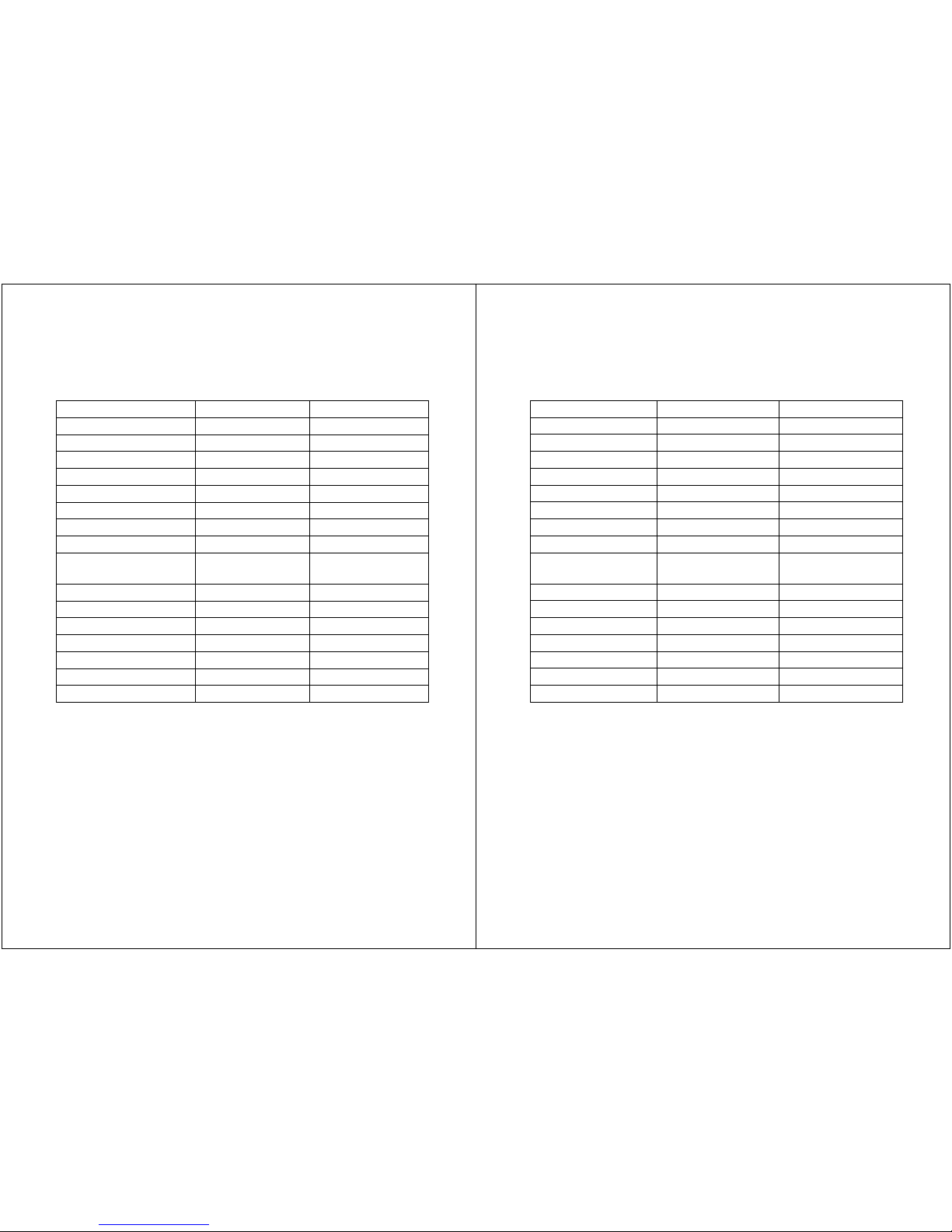
LCD Monitor Specifications
Specification/Model Standard F100 Standard F120
Panel Type VGA TFT SVGA TFT
Recommended Res. 640x480 800x600
Screen Diagonal Size 10.4 12.1
Display Colors 6bit 262K colors 6bit 262K colors
Brightness (Cd/m²) 400 400
Contrast ratio (X : 1) 300 500
Viewing angle L/R/U/D 60/60/40/50 60/60/40/55
Display Area (mm) 211.2x158.4 246.0x184.5
Input Signals
VGA, Comp & S-
video
VGA, Comp & S-
video
Power Consumption 30 Watt Max 36 Watt Max
Operating temp. 0-50°C 0-50°C
Storage temp. -20°C to 65°C -20°C to 65°C
Operating humidity 10-90% ** 10-90% **
Dimension (Standard) 289x236.4x43 319.5x260x45
Weight (kg) 2.5 – 4 3.2 – 4.6
** NOTE: Non Condensing
- 15 -
Standard F150 Standard F170 Standard F190
XVGA TFT SXVGA TFT SXVGA TFT
1024x768 1280x1024 1280x1024
15.0 17.0 19.0
16M Colors 16M Colors 16M Colors
300 300 300
550 800 800
80/80/80/80 80/80/70/70 89/89/80/80
304.1x228.1 337.9x270.3 376.3x301
VGA, Comp & S-
video
VGA, Comp & S-
video
VGA, Comp & S-
video
40 Watt Max 40 Watt Max 40 Watt Max
0-50°C 0-50°C 0-50°C
-20°C to 65°C -20°C to 65°C -20°C to 65°C
10-90% ** 10-90% ** 10-90% **
382x302x56 411x348x60 460x392x64.6
4.2 – 5.9 5.5 – 7.2 5.7 - 8.5
** NOTE: Non Condensing
Page 9
- 16 -
LUVOX AIO (All-In-One) systems
Description
LUVOX models F150, F170 and F190 can be equipped with a
MINI-ITX embedded industrial grade motherboard. This creates
major advantages compared with traditional setups of PC and
monitors connected over VGA like smaller application designs and
reduced hardware costs. AIO image quality is also way above that
of a traditional VGA setup because the LCD component inside the
device interfacing with the motherboard on a digital level which
creates the clearest image possible.
Another advantage specific for LUVOX AIO systems is their broad
spectrum of possible ELO touch screen technologies. ELO touch
screens are available for a wide variety of uses, from point of sale
to kiosks, medical and industrial equipment, and gaming systems.
ELO is the global standard in high-end quality touch components
for over 30 years and includes reliability, accuracy, clarity and
responsiveness.
- 17 -
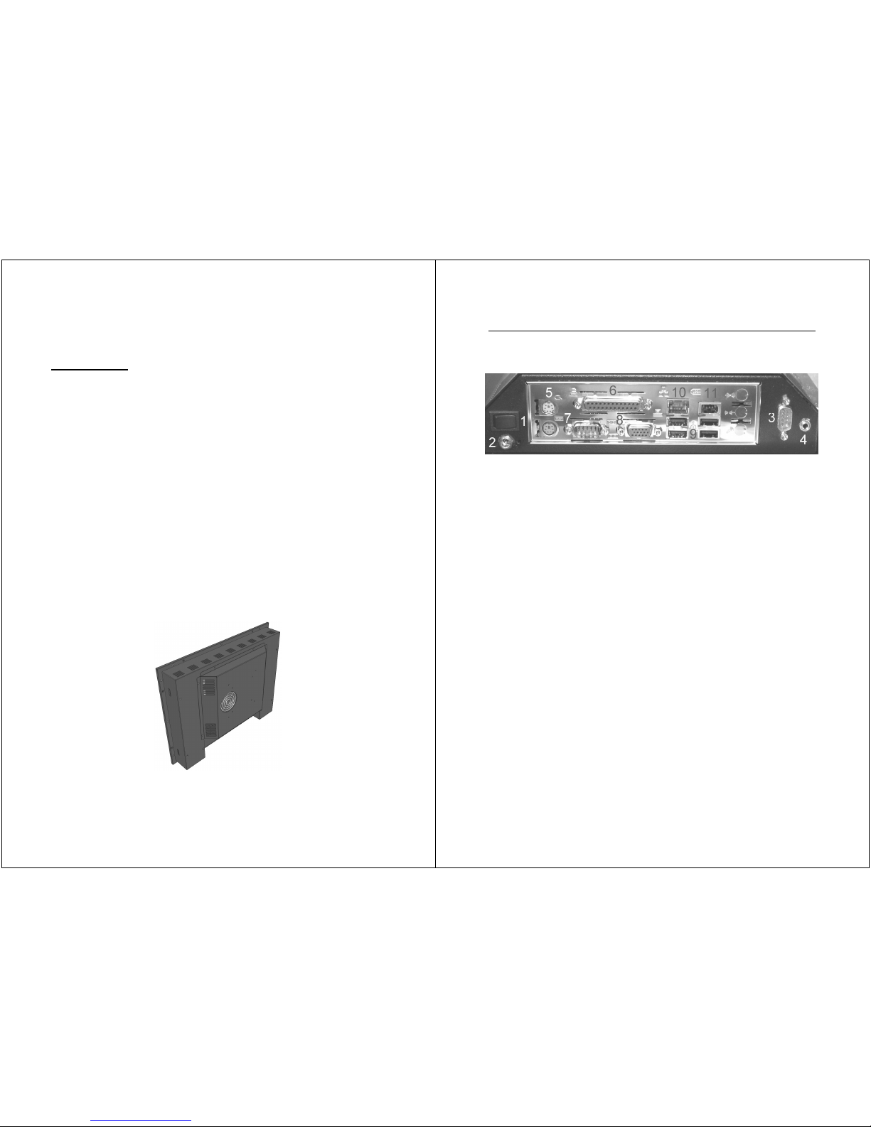
Connector Layout (standard LUVOX AIO system)
(Chapter applies to standard LUVOX All-In-One systems only)
1. POWER ON toggle switch (connected to main board)
2. DC POWER jack (Center pin +)
3. RS232 port - COM2
4. AUDIO (stereo line-out)
5. PS/2 Keyboard & mouse
6. PARALLEL port LPT1
7. RS232 port – COM1
8. VGA out (For Independent 2
nd
VGA monitor)
9. USB 2.0 (4x)
10. ETHERNET
11. FIREWIRE
NOTE: LUVOX AIO systems have a broad range of optional
features available and are frequently build in project based
custom series. This means your monitor could have extra
connectors available for different purpose.
Page 10
- 18 -
Accessing main-board area
Although a LUVOX AIO system contains no user serviceable parts
inside, it may be desired for users to have access to the main
board area of the device to:
• Expand random access memory
• Reset BIOS settings *
• Replace Lithium battery cells
• Access internal CF slot
• …
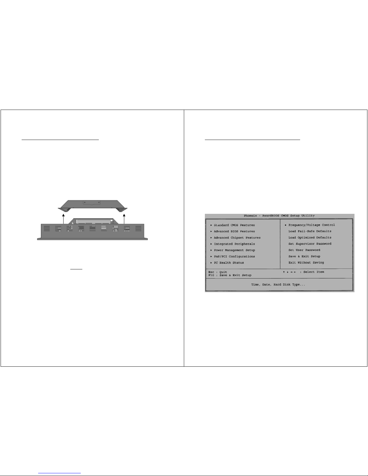
1. Power down your LUVOX AIO device
2. Disconnect all power cabling
3. Remove the 8 white M3 screws which secure the cover
(black screws are never
user serviceable)
4. Remove cover and disconnect the optional external Compact
Flash slots when ought necessary and present**.
5. Carry out the desired service
(Consult the main board’s installation guide for specific
information about the main board)
6. Replace cover in reverse order
*NOTE: When a BIOS reset is carried out , the system’s LCD
panel has to be reactivated by using an external VGA monitor
(see next chapter)
**NOTE: Make sure you re-connect the IDE cable correct. The
red edge of the IDE cable must match with PIN 1 of the CF
socket.
- 19 -
LUVOX AIO Default BIOS settings
It is important to know what to understand under default BIOS
settings. When the system’s BIOS is reset, the system will return
to the default setting according the main board. Meanwhile
LUVOX default BIOS settings done during production of your
LUVOX AIO deviate from these.
The BIOS settings carried out during production are now briefly
summarized. It may help you to re-initialize your system in case
this necessity would ever occur.
(Consult the main board’s installation guide for more specific
information about the main board’s BIOS)
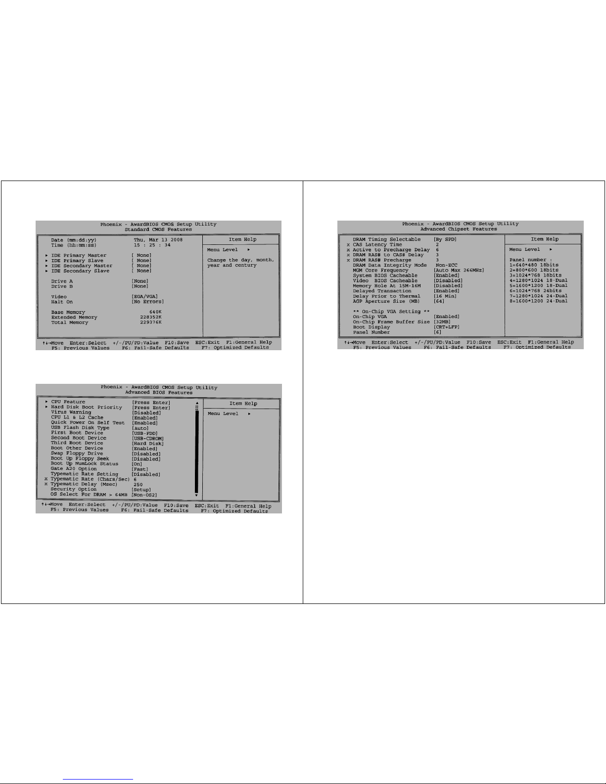
Fig 1.) Press DEL during startup to enter the main BIOS screen
Page 11
- 20 -
Fig 2.) (Standard CMOS Features) LUVOX AIO systems are
designed to operate without PS/2 peripherals and since there is
no floppy disk present, the options ‘Drive A’ & ‘Drive B’ should be
set to [None] and ‘Halt On’ should be toggled to [No Errors]
Fig 3.) (Advanced BIOS Features) Boot sequence 1.USB-FDD,
2.USB-CD-ROM, 3.HDD. ‘Boot Other Device’ must be [enabled] in
order to boot from removable media like USB and CFII cards. The
sequence between these can be changed at ‘Hard Disk Boot
Priority’
- 21 -
Fig 4.) (Standard Chipset Features) ‘AGP Aperture Size’
(representing the amount of system RAM shared with the graphic
stage) is set to [64MB]. You may increase this amount when
running video intensive applications (at expense of system’s
RAM). In order to have the internal LCD functioning you must
define the LCD panel type that is integrated. A LUVOX AIO F150
‘Panel Number’ should be [6] for newer devices or [3] for devices
made before February 2006. For LUVOX AIO F170 and F190 this
should always be [7]. Make sure you leave ‘Boot Display’ to
[CRT+LCD].
NOTE: When your LUVOX AIO F150 system was ever carried in
for service, your device may be produced before Feb 2006, but
have a panel type [6] on board. When booting the system with an
incorrect panel number set in the BIOS, this will not damage your
device although a distorted image will occur on the screen. In this
case the screen may be unreadable, connect an external screen
to the VGA in order to see BIOS information.
Page 12
- 22 -
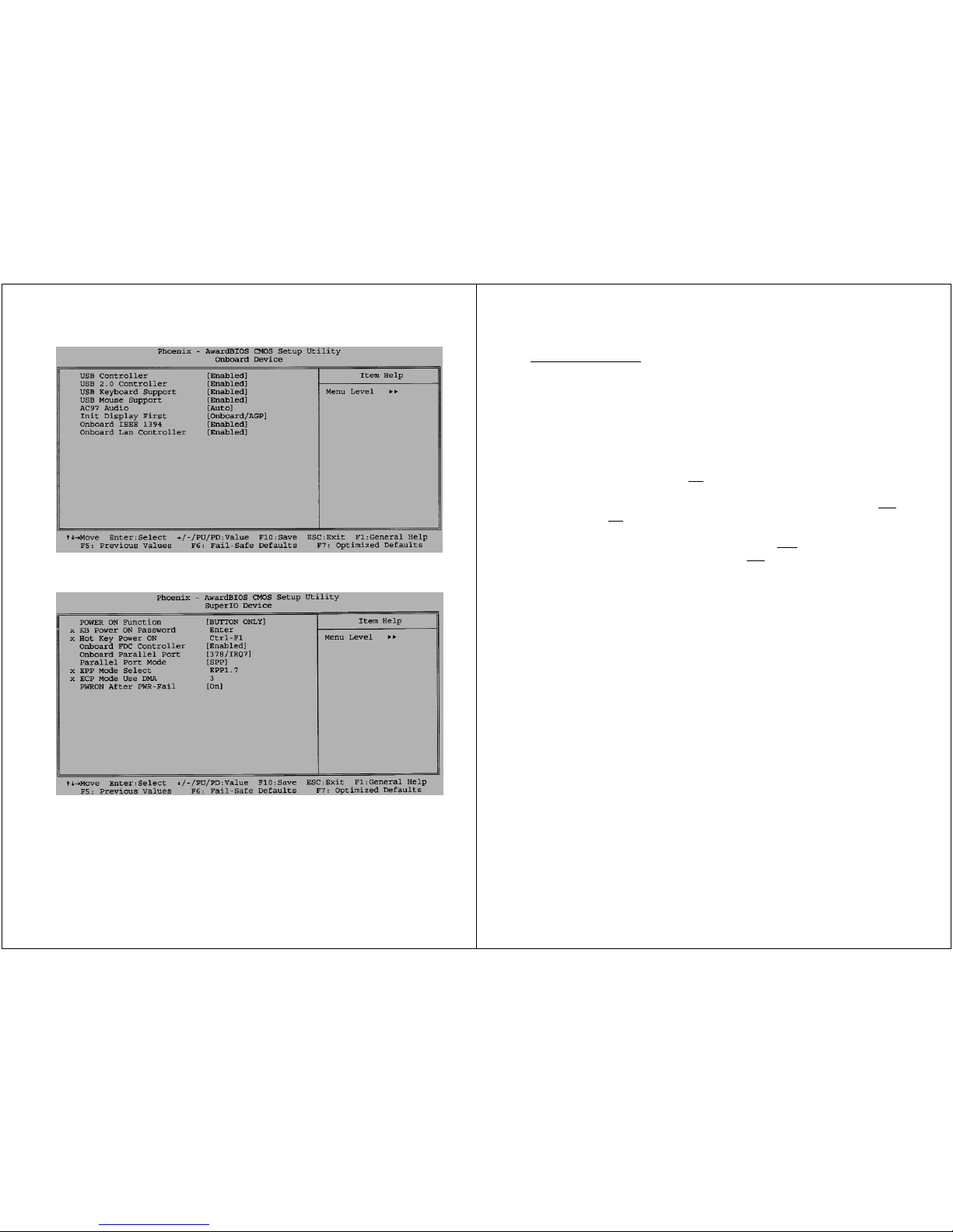
Fig 5.)(Integrated Peripherals/Onboard Device) Turn on full USB
mouse & keyboard control.
Fig 6.)( Integrated Peripherals/SuperIO Device) LUVOX AIO
systems are most frequently used as panel mount devices leaving
the power switch out of reach. Therefore ‘PWRON After PWR-Fail’
is set to [On] (This will make the device powering on each time
DC power returns after being removed)
- 23 -
Storage setups
The Hard disk / Storage configuration of a LUVOX AIO device is
available in 4 setups.
1. 80GB Internal Hard Disk Drive (IDE)
2. 4GB Internal Flash Drive (Single Internal TrueIDE mode
Compact Flash socket & 4GB industrial grade TrueIDE mode
UDMA CF Card included) No
Hard Disk Drive
3. Double External TrueIDE mode CF socket (CF Cards not
included), No
Hard Disk Drive
4. 80GB Internal Hard Disk Drive (IDE) and Double External
TrueIDE mode CF socket (CF Cards not
included).
Although it is proven possible to install and run a standard
Microsoft Windows XP PRO installation from a TrueIDE
mode UDMA CF card setup, LUVOX AIO Systems can only
be ordered with Windows XP PRO in setup 1 and 4.
When it is required to run a Microsoft Windows XP environment
from a TrueIDE mode CF Card, it is strongly advised to use the
componentized version Microsoft Windows XP Embedded.
With the Windows XP Embedded Enhanced Write Filter (EWF), it
is possible to protect the system at volume level and redirect all
disk writes to a protected drive in the system’s memory. This will
prevent the CF card from an instant wear out.
LUVOX AIO System are not offered with Windows XP Embedded,
although DOBIT NV, as the constructor, can assist customers in
building a custom Windows XP Embedded footprint for LUVOX AIO
Systems on project basis.
This way of custom and project based OS building assistance can
also be offered for a LINUX platform.
Please, contact our sales department for more information.
Page 13
- 24 -
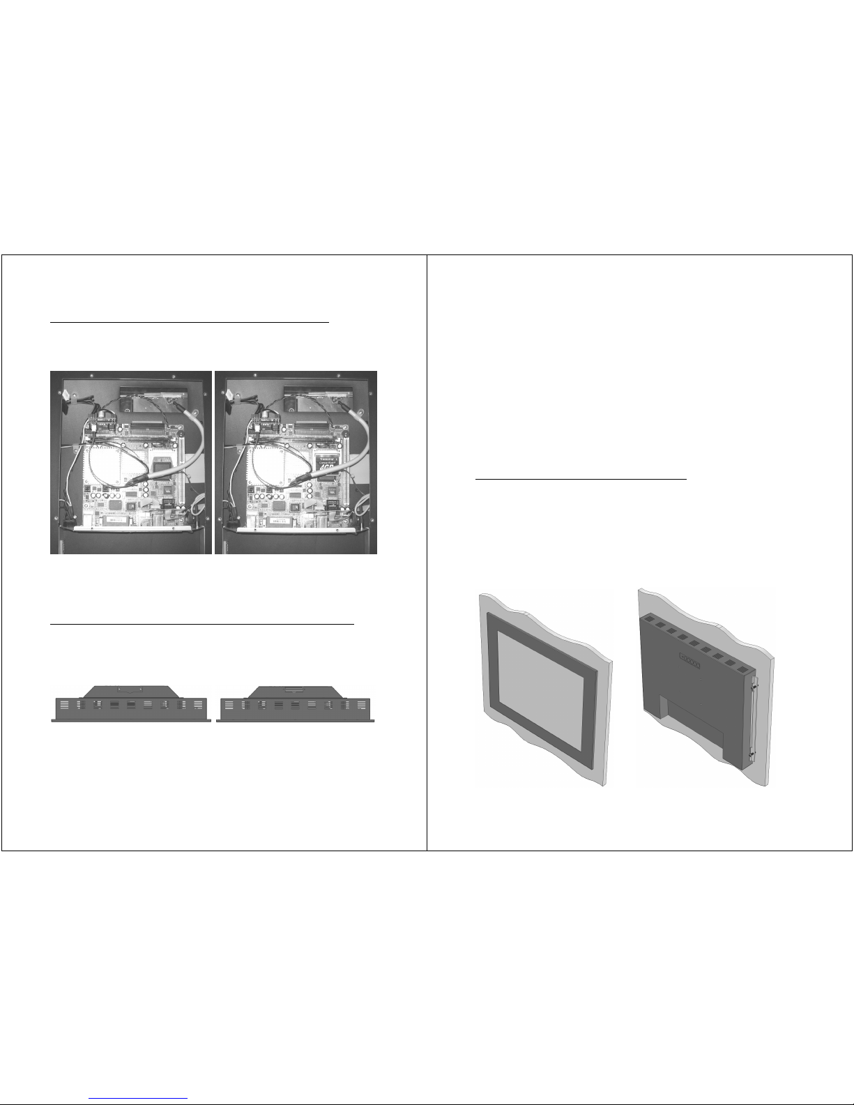
Accessing the internal single True IDE CF Card or Socket
Open the main-board area as described on page 19. Once you
have removed the cover you can access the internal CF Socket:
Always carefully insert the CF card with the lipped edge facing
towards the main board. Opposite insertion will damage the
socket’s pins.
Accessing the external double True IDE CF Cards and Sockets
Remove the cover by unscrewing both M3 bolts. The upper slot as
seen in the drawing below is slot 2, the lower is slot 1. These slot
numbers correspond with the IDE port’s master (1) and slave (2).
Always carefully insert the CF cards with the lipped edge facing
away from the device. Opposite insertion will damage the socket’s
pins. Replace the cover to prevent the cards from vibrating out of
the device.
- 25 -
LUVOX Panel Mounting
LUVOX devices are designed as panel mount devices. This means
the device is inserted into the dedicated cutout from the front
side of the enclosure and subsequently secured from the
backside.
There are basically 2 manners to carry out the backside securing.
• Securing with Front Mount Brackets
• Securing with Side Skirt Bolts
Securing with Front Mount Brackets
We advice this way of securing when the enclosure’s material is
rather thick, board are woodlike. Insert your device into the
dedicated cutout, attach both Front Mount Brackets to the left
and right side of the device and start tightening up the
construction with the included M4x30 mm screws.
Page 14
- 26 -
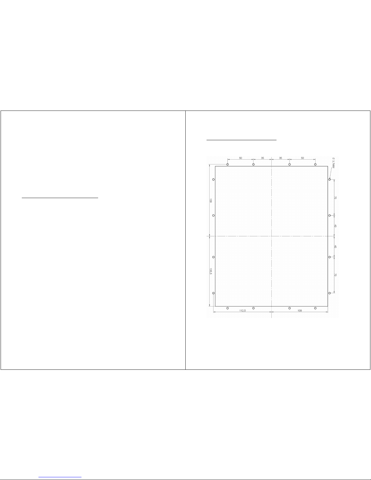
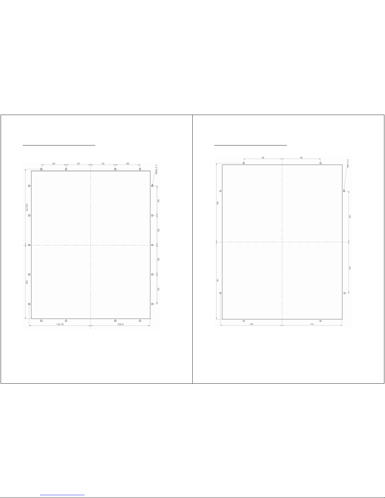
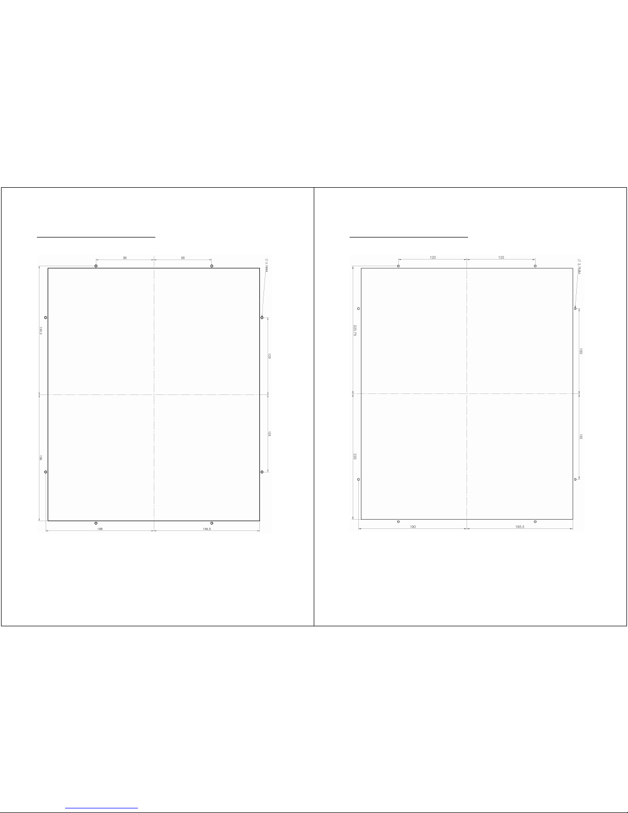
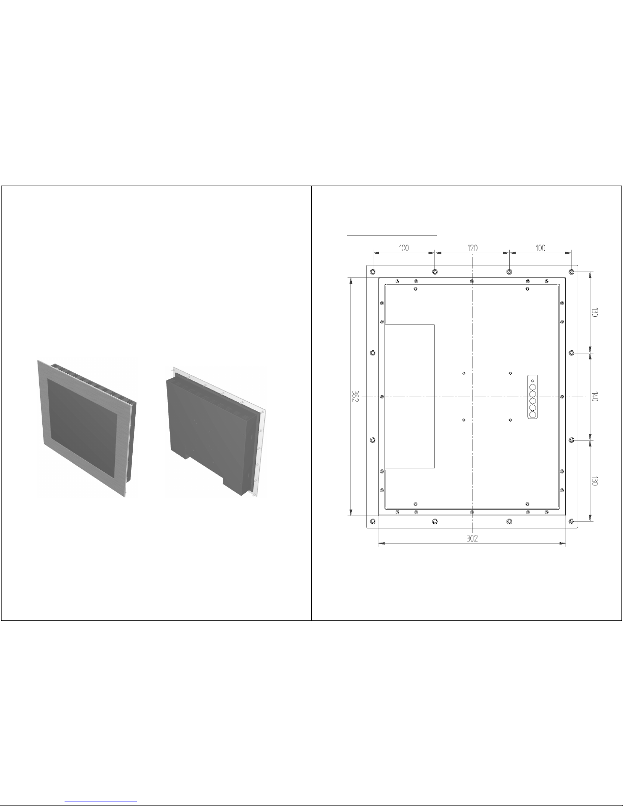
Saw or mill the rectangular cutout as advised in this table below:
• LUVOX F100 272 mm x 218 mm
• LUVOX F120 302 mm x 242 mm
• LUVOX F150 362 mm x 282 mm
• LUVOX F170 392 mm x 330 mm
• LUVOX F190 440 mm x 372 mm
NOTE: Maximum thickness of enclosure’s material is 19 mm
when securing with Front Mount Brackets.
Securing with Side Skirt Bolts
We advice this way of securing when the enclosure’s material is
sheet metal or any other material with a thickness between 1 and
3 mm. Use the free M3 holes in the side skirts of your LUVOX
device to secure the device.
This way of mounting is possible for any material thickness but
the standard M3x6 screws will appear to short. Please, be careful
when selecting longer screws to install the device in materials
thicker then 3 mm. The holes in the side skirts are 5 mm in
depth. Make sure you do not use screws that exceed this
insertion because this will indicate as permanent bumps in the
front of the device.
CAD drawings for each cutout are available on request.
We can also assist customers with the creation of perfect
apertures in (stainless) steel parts (and other materials) like
doors and enclosures. This is done with CNC cutting devices as
laser- and water jet.
Please, contact our sales department for more information.
- 27 -
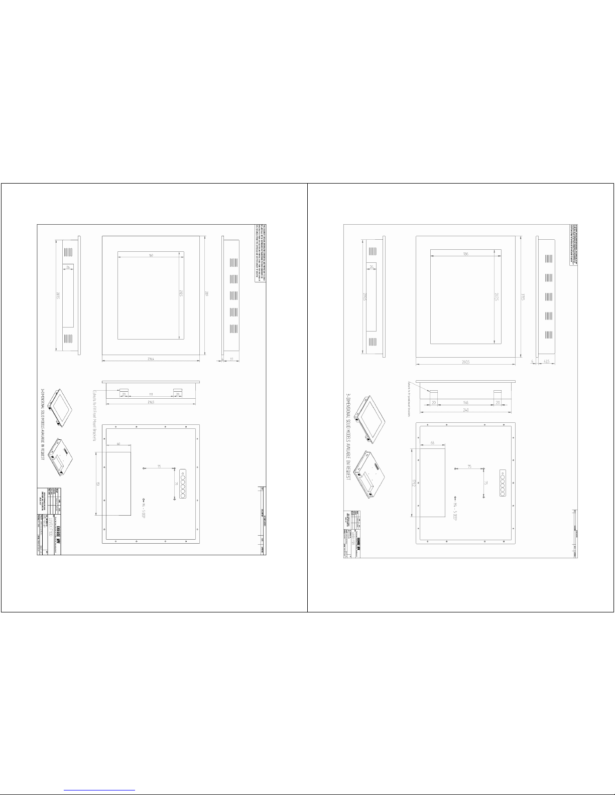
LUVOX F100 Panel Mount Cutout
Page 15
- 28 -
LUVOX F120 Panel Mount Cutout
- 29 -
LUVOX F150 Panel Mount Cutout
Page 16
- 30 -
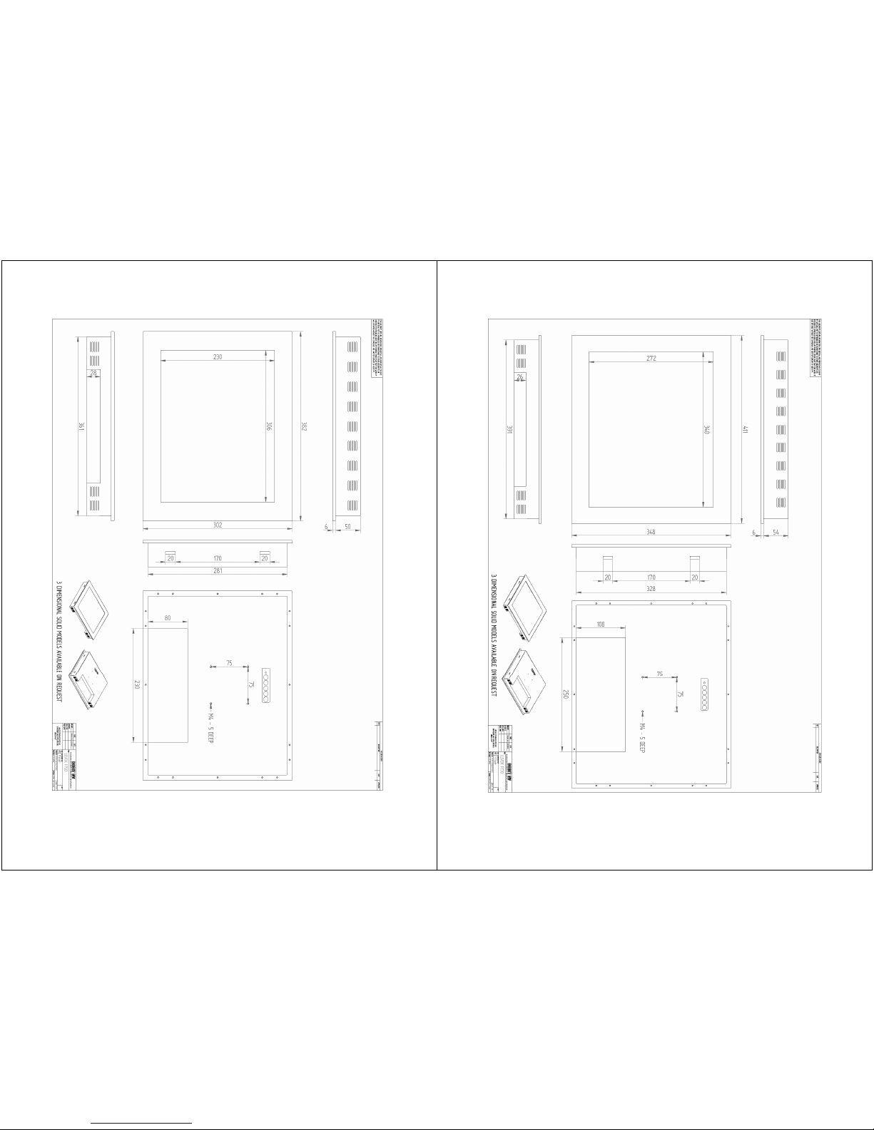
LUVOX F170 Panel Mount Cutout
- 31 -
LUVOX F190 Panel Mount Cutout
Page 17
- 32 -
LUVOX Optional features
ProLine
Description
(applies to models F150, F170 & F190 only, AIO systems & LCD
Monitor)
LUVOX devices are kept on stock in large quantities for each
standard model. This way we are able to ship standard models
within 10 workdays max. However, some optional features require
stock units to return to the production plant to be rebuild, having
the specific feature included.
• IP65 front (AIO & Monitor)
• RS-232 & USB Combo Touch Interface (Monitor Only)
• 12Vin or 24Vin pluggable terminal block (AIO & Monitor)
• Integrated 4 Watt STEREO speaker set (AIO & Monitor)
Whenever at least one
of these optional features is demanded, it
is required to order your LUVOX device in the extended
configuration mode, which is sold as ProLine.
However, to contribute to you as our customer, each LUVOX
device is provided as follows:
• Each LUVOX LCD Monitor, ordered as ProLine, will always be
equipped with an RS-232 & USB Combo Touch Interface when
possible (ACCUTOUCH, INTELLITOUCH and SURFACE
CAPACITIVE)
• Each LUVOX device (LCD monitor & AIO system) ordered as
ProLine, will always be equipped with a PHOENIX CONTACT
pluggable terminal block (Industrial standard).
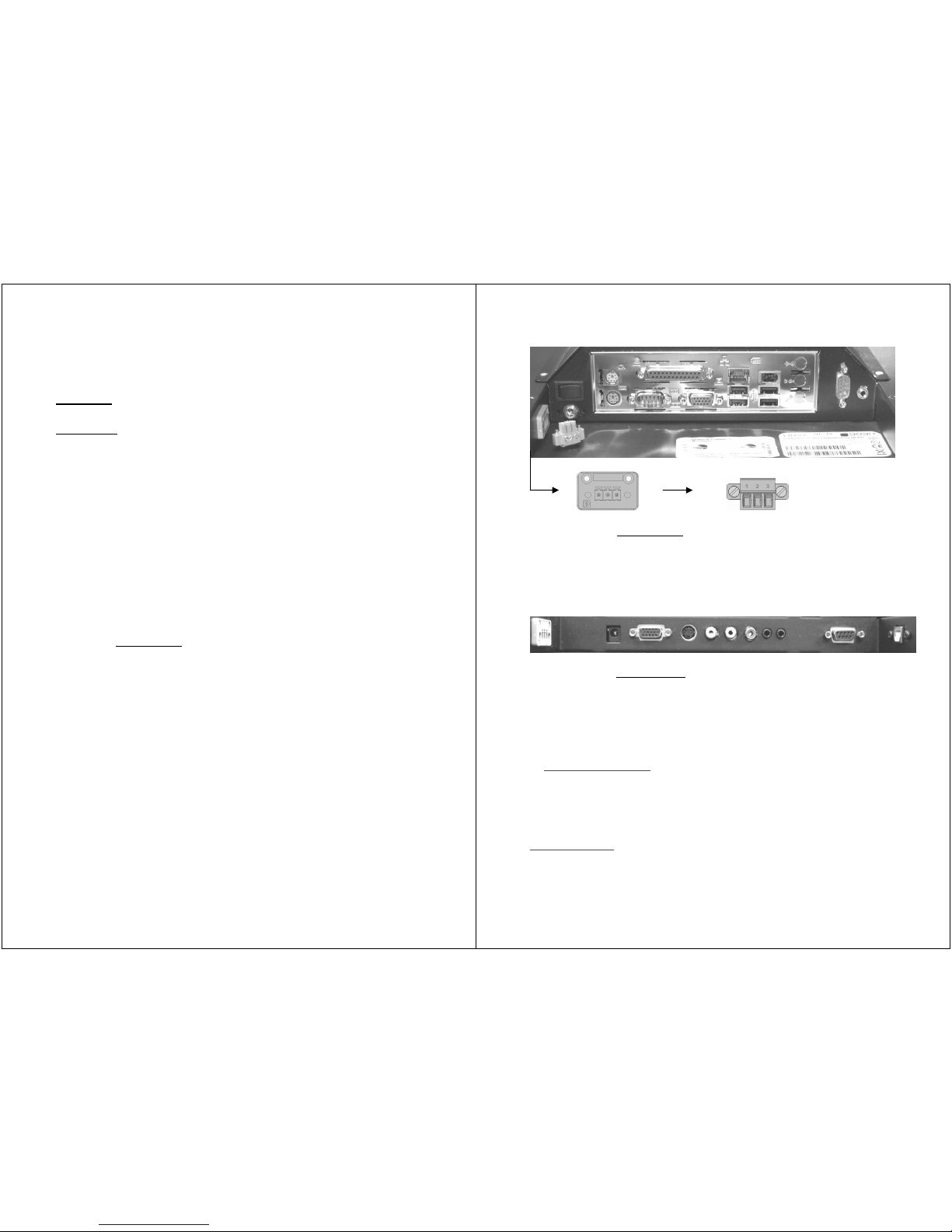
- 33 -
Typical LUVOX AIO system
equipped as ProLine: The connector
bay is expanded with an industrial style power connector socket
(PHOENIX CONTACT MC 1.5/3-GF-3.81). PIN 1: 0V , PIN 2: Earth,
Pin3: +12/24V. The corresponding connector (PHOENIX CONTACT
MC 1.5/3-STF-3.81 partnr 18277116) is included with your
LUVOX device.
Typical LUVOX LCD Monitor
equipped as ProLine. The connector
bay is, behalf the industrial style power connector socket, also
expanded with a Combo (RS-232 & USB) touch interface.
IMPORTANT! Please notice ProLine configured LUVOX All-In-
One systems have two power inputs. The 5.5mm DC power jack
is
ALWAYS THE SAME voltage as the extra 3 Pins socket, 24V or
12V depending on your configuration. The label defines the power
input configuration.
IMPORTANT! Please notice ProLine configured LUVOX LCD
monitors have two power inputs. The 5.5mm DC power jack is
ALWAYS a 12V input, while the extra 3 Pins socket is a 12V or
24V input, depending on your configuration. The label defines the
power input configuration.
Page 18

- 34 -
IP65 Front
Description
LUVOX F150, F170 and F190 devices* (AIO systems and LCD
monitors) are configurable with an IP65 front**. Since
01/01/2010 each IP65 fronts is manufactured in grade 316 (16%
chromium, 10% nickel and 2% molybdenum , Euro norm 1.4401)
which has highly improved corrosion resistance in a wide variety
of corrosive environments.***
The backside of the IP65 front is sealed with a 2MM white
(NS/SBR) rubber sealing. The rubber is carefully selected and
advised by ERIKS group, worldwide leader in rubber- and sealing
technology. The sealing meets specific properties demanded in
food- and pharmaceutical industries and is approved with the FDA
177.2600 standard for rubber articles.
Perfect IP65 sealing is accomplished only in combination with
plain glass (NOTOUCH) or ELO ACCUTOUCH when interactive use
is desired. ELO INTELLITOUCH, ELO SURFACE CAPACITIVE and
ELO CARROLLTOUCH are no
suitable technologies in combination
with the IP65 front.
We can only guarantee IP65 sealing between monitor and
enclosure when the enclosure’s material is rigid enough to hold all
tightening forces. Therefore, sheet metal thickness of an
enclosure must be at least 1.7mm.
*NOTE: IP65 fronts for models F100 and F120 may exist but are
only produced in project based custom series.
** NOTE: The IP65 front is not a retro-fit option. LCD monitors
and AIO systems must be ordered with IP65 front in combination
with the ProLine option.
*** NOTE: All IP65 fronts manufactured before 31/12/2009 are
grade 304, (18% chromium and 8% nickel, Euro norm 1.4301) a
versatile and widely used standard for stainless steel applications.
- 35 -
European protection classification conform DIN EN 60529 is
offered by the letters IP (Ingress Protection) and two digits. The
first digit indicates protection for persons and equipment. The
second digit indicates protection against water. For IP65* this can
be interpreted as:
• FIRST DIGIT 6
Protection for persons
= protection against touching
dangerous parts. A body (testprobe) of 1.0 mm in diameter
must not be able to enter or the distance between the
accessing probe and dangerous parts is always kept.
Protection for equipment
= protection against dust. 6
indicates dust must not enter at all. The test is carried out in a
chamber in which talcum powder is being kept suspended in
the air. The tested enclosure is kept below the atmospheric
pressure of the environment according to the standard. The
protection is satisfactory if there is no visible dust deposit
within the enclosure after completion of the test.
• SECOND DIGIT 5
Protection from moisture
= Protection against water jets
directed at the enclosure from any direction. A diameter
6.3mm jet nozzle splashes 37.5L in 3 minutes from a distance
of 2.5 to 3M from all sides. Should water have penetrated, it
must not be present in quantities which impair the good
working order of the operating material or represent a safety
hazard, deposit on non-conducting parts where it could lead
to creep currents, come in contact with live parts or coils
which are unsuitable for operating in wet conditions, collect
near the wire end or possibly penetrate the wire.
*NOTE: Relates only to the IP65 front
of a LUVOX device.
Page 19
- 36 -
LUVOX devices with IP65 front are designed to be even more
tough and rugged, the IP65-rated fronts are ideal for use in
harsh, wet and dusty environments or high hygienic , such as:
• Food and beverage
• Pharmaceutical / Cosmetics
• Chemical / Petrochemical
• Biotechnical
• Pulp and paper plants
• Non-vandal outdoor
• …
NOTE: M5 nuts are included. We advice using the provided selflocking hexagon nuts with toothed flange (DIN 6923)
- 37 -
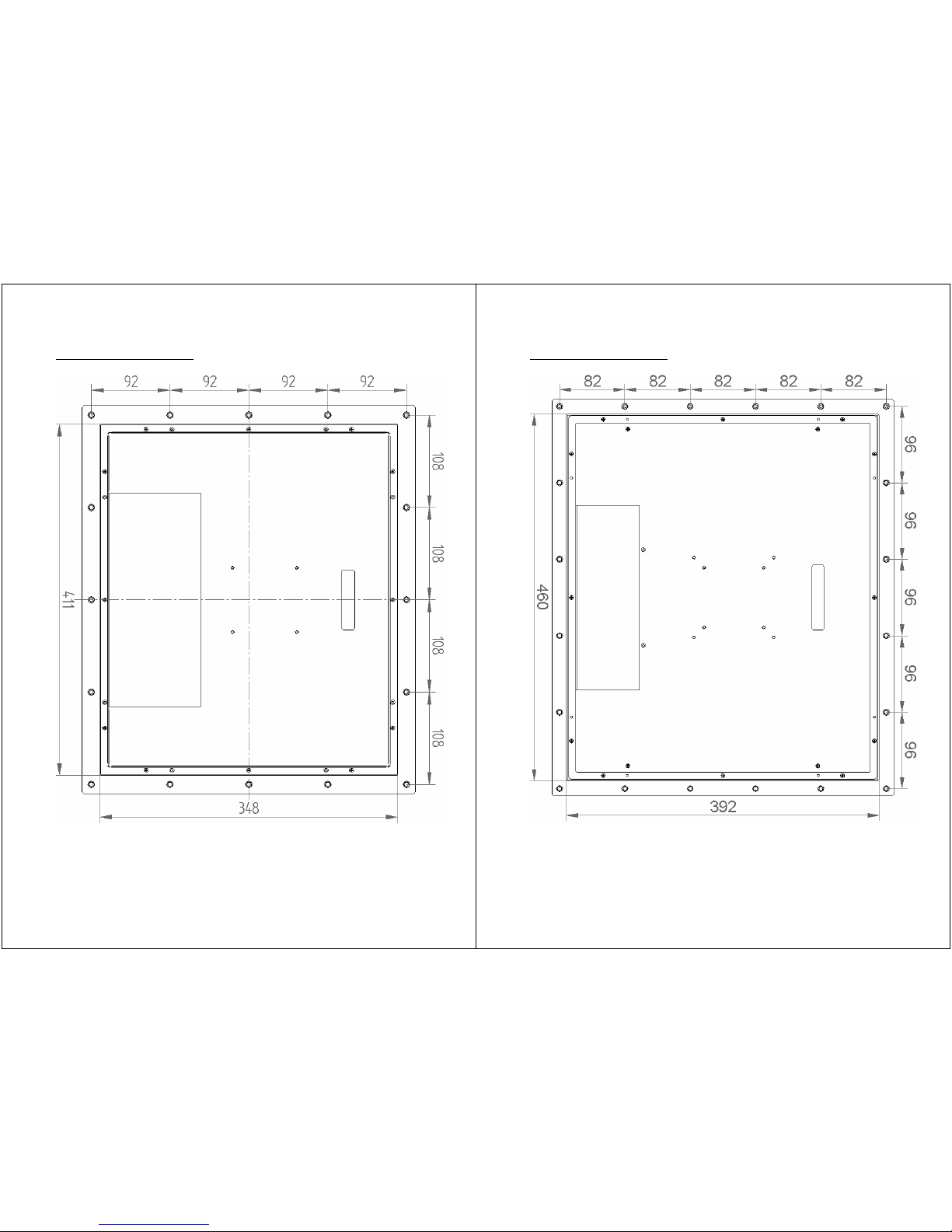
LUVOX F150 IP65 Layout
NOTE: Use cutout of 384 x 304mm and 12 x ø 7mm holes
(3D) CAD drawings available on request.
Page 20
- 38 -
LUVOX F170 IP65 Layout
NOTE: Use cutout of 413 x 350mm and 16 x ø 7mm holes
(3D) CAD drawings available on request .
- 39 -
LUVOX F190 IP65 Layout
NOTE: Use cutout of 462 x 394mm and 20 x ø 7mm holes
(3D) CAD drawings available on request .
Page 21
- 40 -
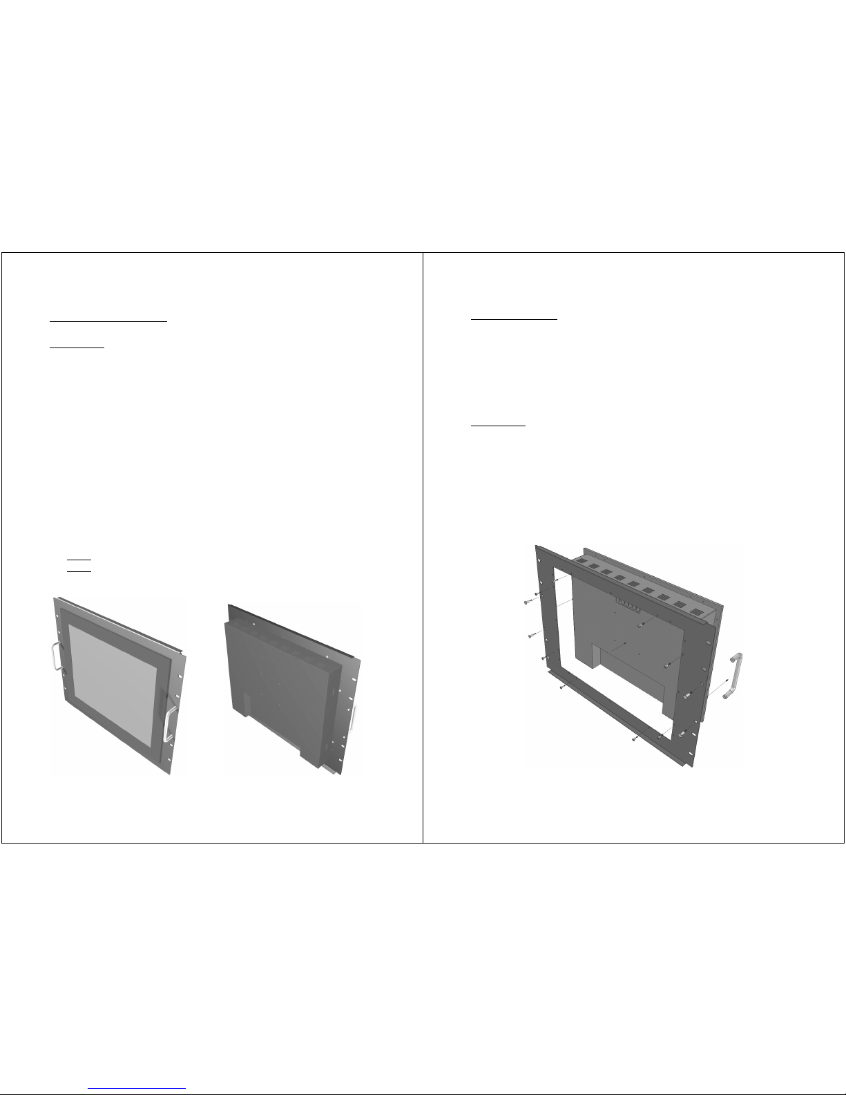
Rack-Mount Bezel
Description
19-inch racks are a standardized (EIA 310-D, IEC 60297 and DIN
41494 SC48D) systems for mounting various electronic modules
in a 19 inches (482.6 mm) wide stack or rack. Equipment
designed to be placed in such racks are typically described as
rack-mountable.
LUVOX F150 and F170 devices (AIO and LCD monitors) are
configurable with a retro-fit black powder coat finished rackmountable bezel.
Rack-mountable devices are always offered as being [x]U in
height. (generally 1U = 1.75 inch or 44.45 mm)
Within this agreement LUVOX Rack Mount Bezels are
respectively:
• F150
: 8U or 355 mm high
• F170
: 9U or 399 mm high
- 41 -
Package Contents
• F150/F170 Rack-mount bezel (black powder coat finish)
• Chrome rack handles and fixing (2x)
• M5 cage nuts (4x)
• M5x12MM bolts (4x)
• Plastic cup washers (4x)
• Side Skirts Bolts (8x)
Installation
Rack-mount bezels for LUVOX devices are retrofit options and are
user-assembled. Use the 8 (M3) bolts to secure your bezel to the
side skirts of the device. Each side has two free M3 holes. Use the
4 (M4) screws to secure the handles to the bezel (If not yet
assembled).
Page 22
- 42 -
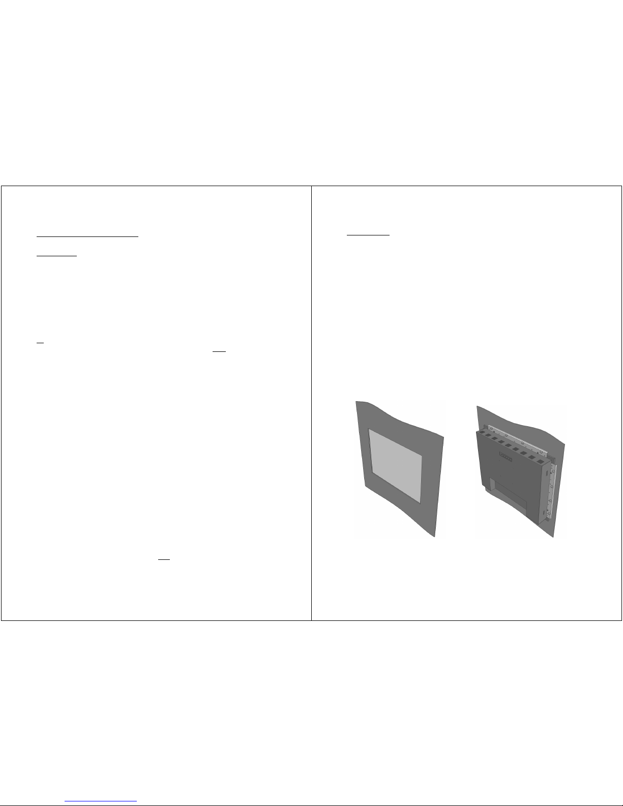
Rear-mount brackets
Description
LUVOX devices are designed as panel mount solutions. Although,
when allowed by the application in terms of space, LUVOX (AIO
and LCD monitors) devices can be mounted in a rear mount
construction. This can be obtained by using a set of rear mount
brackets.
LUVOX rear-mount brackets are ordered in pairs. One pair per
device is sufficient to create a rear mount construction (Left/right
or
top/bottom). Although the construction will be more robust
when using two pairs for one device (Left/right and
top/bottom).
LUVOX rear-mount brackets exist in 4 different lengths:
• 215 mm
• 260 mm
• 320 mm
• 370 mm
The list below indicates which sets must be obtained
corresponding to each different model:
• F100 Left & right 215 mm
Top & bottom 260 mm
• F120 Left & right 215 mm
Top & bottom 260 mm
• F150 Left & right 260 mm
Top & bottom 320 mm
• F170 Left & right 320 mm
Top & bottom 370 mm
• F190 Left & right 370 mm
Top & bottom 370 mm
NOTE: Rear-mount brackets are not
suitable in combination with
ELO INTELLITOUCH.
- 43 -
Instructions
• Create a cutout with the minimal dimensions of the aperture
in the front of your device. You may want to increase these
dimensions when the kiosk material is rather thick. This will
help users touching in corners. Rounding or chamfering the
edges of the aperture will also increase touching comfort.
• Assemble one or both pairs of rear-mount brackets
(depending the operational conditions) to the side skirts of the
device. Use the provided M3 screws and insert these in the
free M3 holes.
• Prepare M4 head threaded studs in case of using sheet metal.
When customer material is not sheet metal, drill Ø4.5MM thru
holes for M4 bolts with nuts (bolts are visible from the front
side). Use no-thru Ø3MM holes and 4MM woodscrews when
having rather thick or woodlike materials (no bolts will be
visible from the front side). Make sure the length of the
screws is smaller then the material’s thickness.
NOTE: (3D) CAD drawings available on request.
Page 23
- 44 -
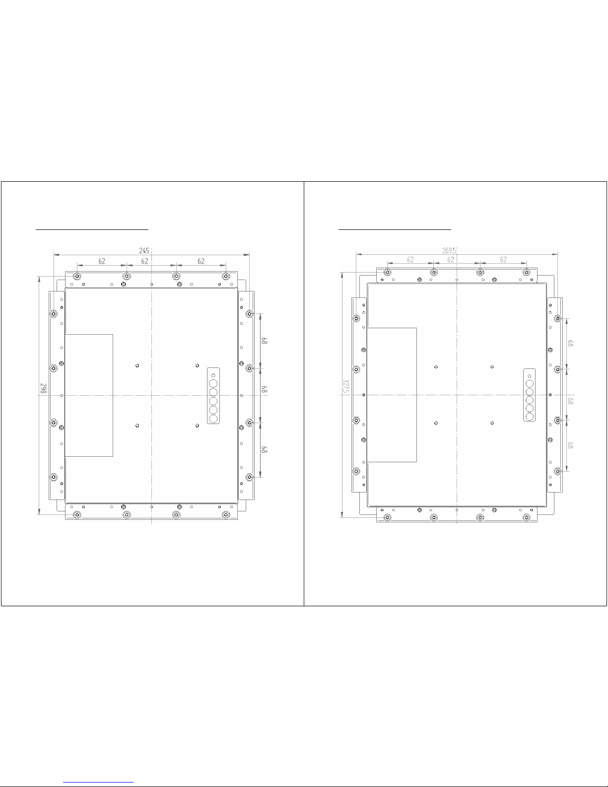
LUVOX F100 Rear-Mount Layout
NOTE: Advised aperture size in front panel: 160 x 212.5mm
- 45 -
LUVOX F120 Rear-Mount Layout
NOTE: Advised aperture size in front panel: 186 x 247.5mm
Page 24
- 46 -
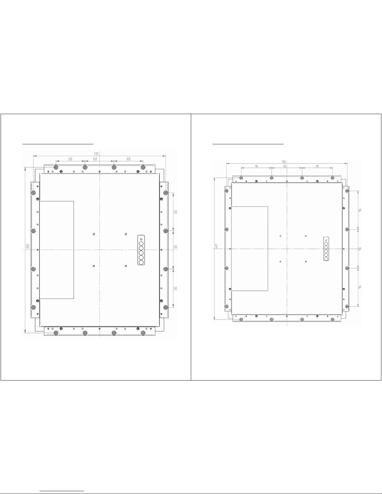
LUVOX F150 Rear-Mount Layout
NOTE: Advised aperture size in front panel: 230 x 306mm
- 47 -
LUVOX F170 Rear-Mount Layout
NOTE: Advised aperture size in front panel: 272 x 340mm
Page 25
- 48 -
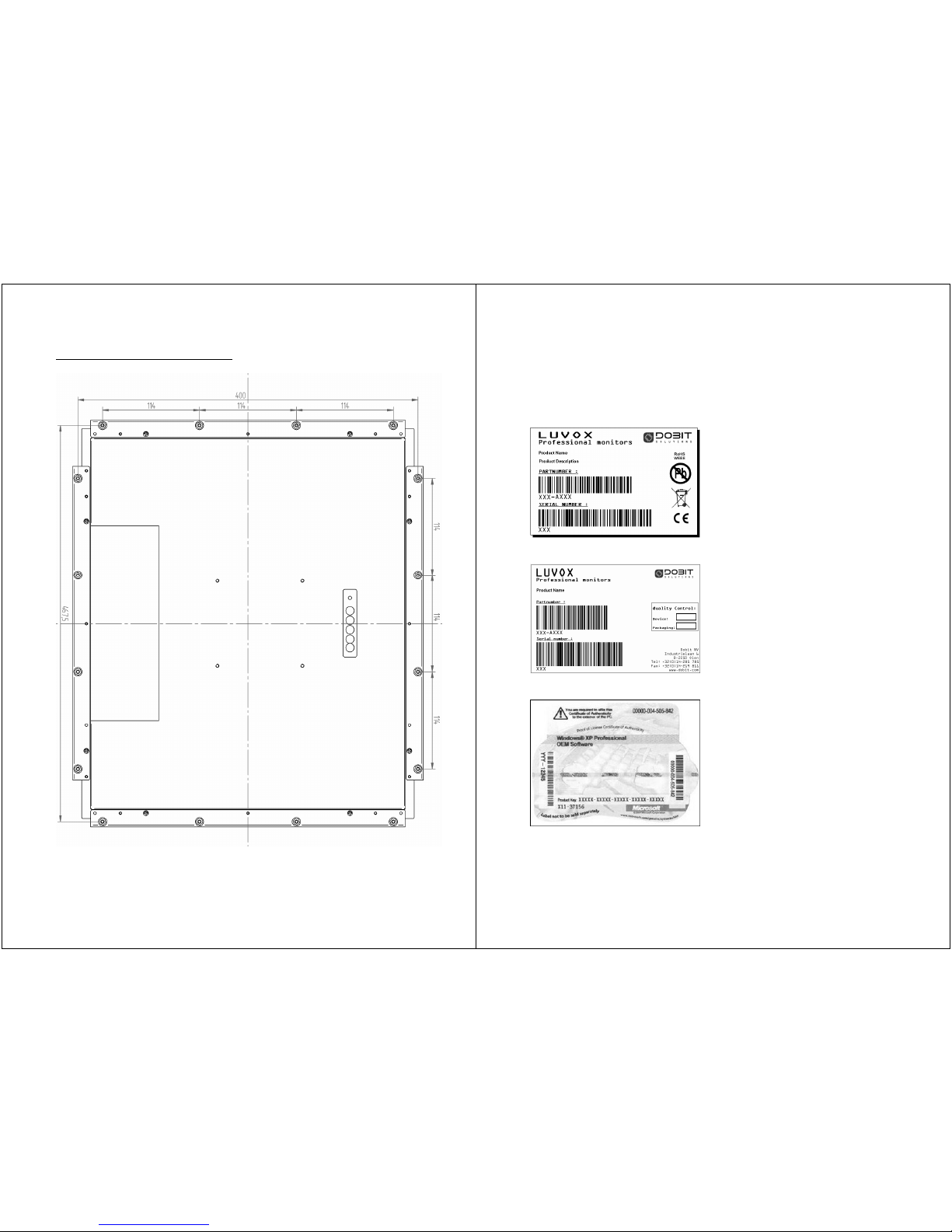
LUVOX F190 Rear-Mount Layout
NOTE: Advised aperture size in front panel: 303 x 378mm
- 49 -
LUVOX Product Identification
Each LUVOX device (monitors and All-In-One systems) is
identified uniquely. Next labels always refer to your device:
LUVOX device Label
LUVOX Box label
MS Windows Certificate of Authenticity (Optional for AIO systems)
Page 26
- 50 -
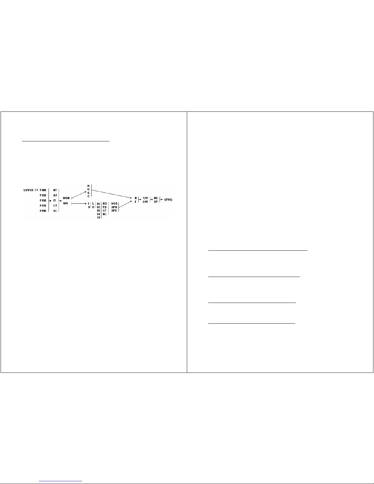
Product Name (Device label & Box label)
Each LUVOX device is highly configurable. This requires solid
product naming. The LUVOX NAMING CONVENTION is a
consistent rule followed by a set of numbers and characters. The
intent should be, that every party is able to identify a LUVOX
device by name, based on the sequence and the knowledge of the
rule.
This diagram will help you identifying your LUVOX device.
• The 1
st
column identifies the diagonal of the screen,
representing 10.4, 12.1, 15.0, 17.0 or 19.0 inch respectively.
• The 2
nd
column describes the presence of an optional touch
technology, representing No Touch, ACCUTOUCH,
INTELLITOUCH, CARROLLTOUCH or Surface Capacitive
respectively.
• The 3
rd
column splits up the device in an LCD Monitor or All-
In-One System respectively.
• The 4
th
column describes the touch interface in case of the
device being an LCD monitor representing No interface, USB,
Serial or Both (Combo). The 4
th
column is of no user
importance in case of the device being an All-In-One System.
• The 5
th
column represents the processor type being low speed
passive cooled or high speed active cooled.*
• The 6
th
column represents the amount of system RAM as 128,
256, 512, 1024 or 2048 respectively.
• The 7
th
column represents the type of drive storage
subsequently as Hard disk drive, Internal CF Flash Disk drive,
Double external CF slot (CF cards are not included) or Both
Hard Disk drive and Double external CF slot (CF cards not
included)
- 51 -
• The 8
th
column is related to the operating system installed on
the device. Representing No OS, MS Windows XP Pro NL or MS
Windows XP Pro EN.
• The 9
th
column defines the device being equipped as
Standard(N) or ProLine(E).
• The 10
th
column is the operating voltage of the device (please,
refer to page 34)
• The 11
th
column defines the presence of an internal speaker
system.
• The additional IP65 postfix points to the unit being equipped
with an IP65 Stainless Steel Front (= ACCUTOUCH or NO
touch).
NOTE: It is not possible to define the processor’s type and speed
out of the device’s product name. DOBIT, as the constructor, will
always stock the most appropriate INTEL processors in terms of
cost and performance available on the market at that moment.
Current processor type’s and speeds are always reported in the
product description, our website and the latest up-to-date sales
documentation.
Product Description (Device label & Box label)
This is the brief synthesis of above, containing the device’s most
important or extra specific properties.
Product number (Device label & Box label)
This number represent the constructor’s (DOBIT) part number of
the article.
Serial number (Device label & Box label)
This is the unique string identifying your LUVOX device.
Quality control compartment (Box label)
These two check-boxes are provided for internal quality control.
Both check-boxes will contain the tag of the quality engineer who
has checked the functionality of the device and the completeness
of the package’s content.
Page 27

- 52 -
Microsoft Windows Certificate of Authenticity (COA)
This Certificate of Authenticity (COA) is a label to help you
identify the genuine Microsoft® Windows® software. Without it,
you will not have a legal license to run the Windows software on
the device. It is a visual identifier that assists in determining
whether your Microsoft software is genuine.
- 53 -
LUVOX Service Information
A LUVOX device contains no user serviceable parts inside. Please
contact our RMA department or use our online RMA tool if you
need any information or help with LUVOX product service.
http://www.dobit.com/eline/master.php
Warranty period is standard 1 year from date of purchase for all
LUVOX devices sold before 31/12/2009. This warranty period is
extended to 3 years standard from date of purchase for all LUVOX
devices sold after 01/01/2010.
Warranty is only valid when the device is judged to be defective by
reason of improper workmanship and/or materials. In this case any
defective part of the device shall be repaired or replaced without
charge for the part(s) and labor expense within the warranty
period.
Warranty is not valid in case of reasonable technical judgment
determining the defect caused by prevalent wear and tear or any
abuse, misuse, neglect or accidental damage.
A device carried in for RMA without any valid product label, will
not
be serviced under warranty.
Page 28
- 54 -
- 55 -
Page 29
- 56 -
NOTE: LUVOX AIO devices increase 30mm in depth
- 57 -
NOTE: LUVOX AIO devices increase 30mm in depth
Page 30
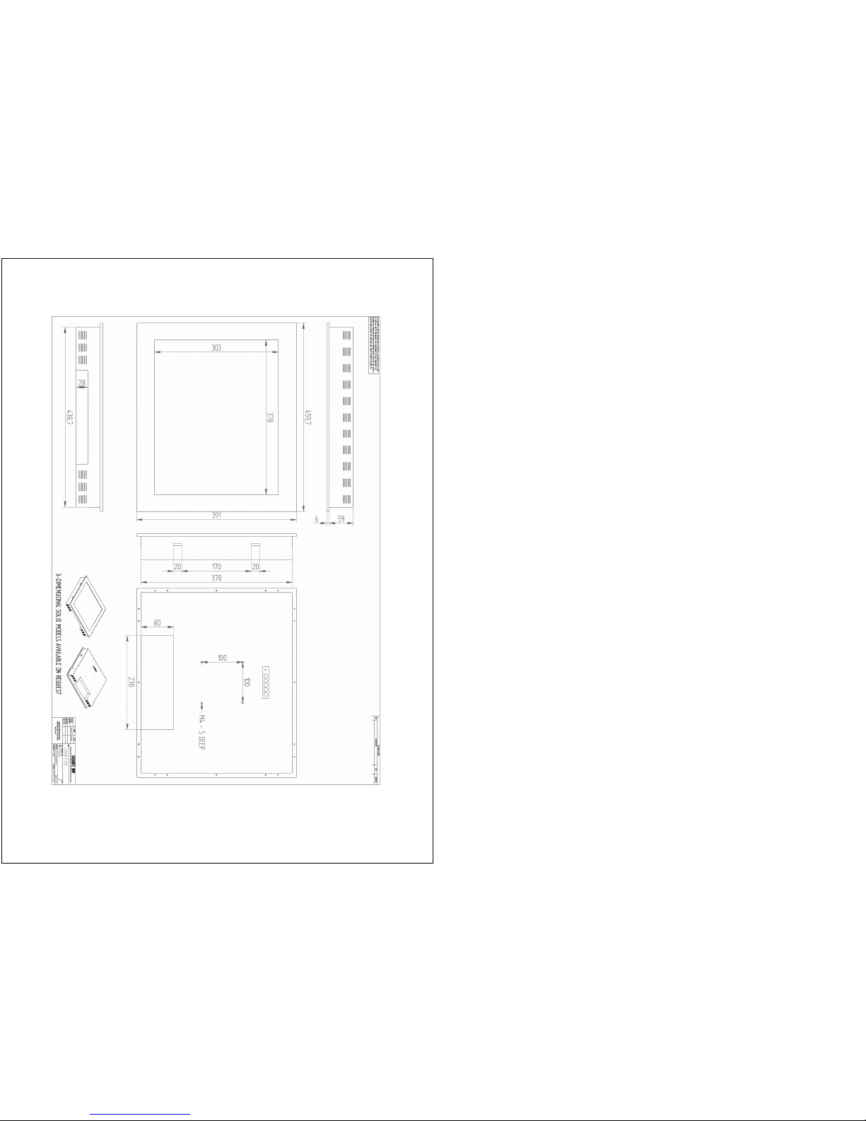
- 58 -
NOTE: LUVOX AIO devices increase 30mm in depth
 Loading...