

Page 1
GB
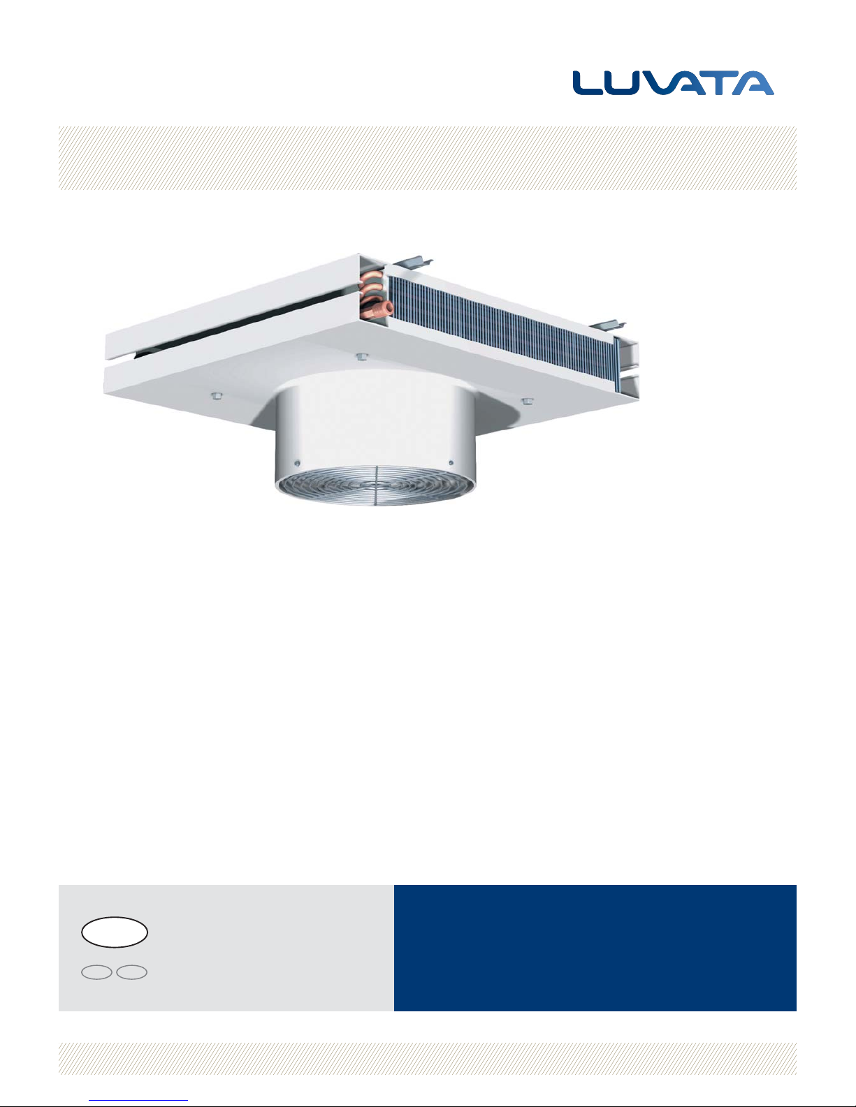
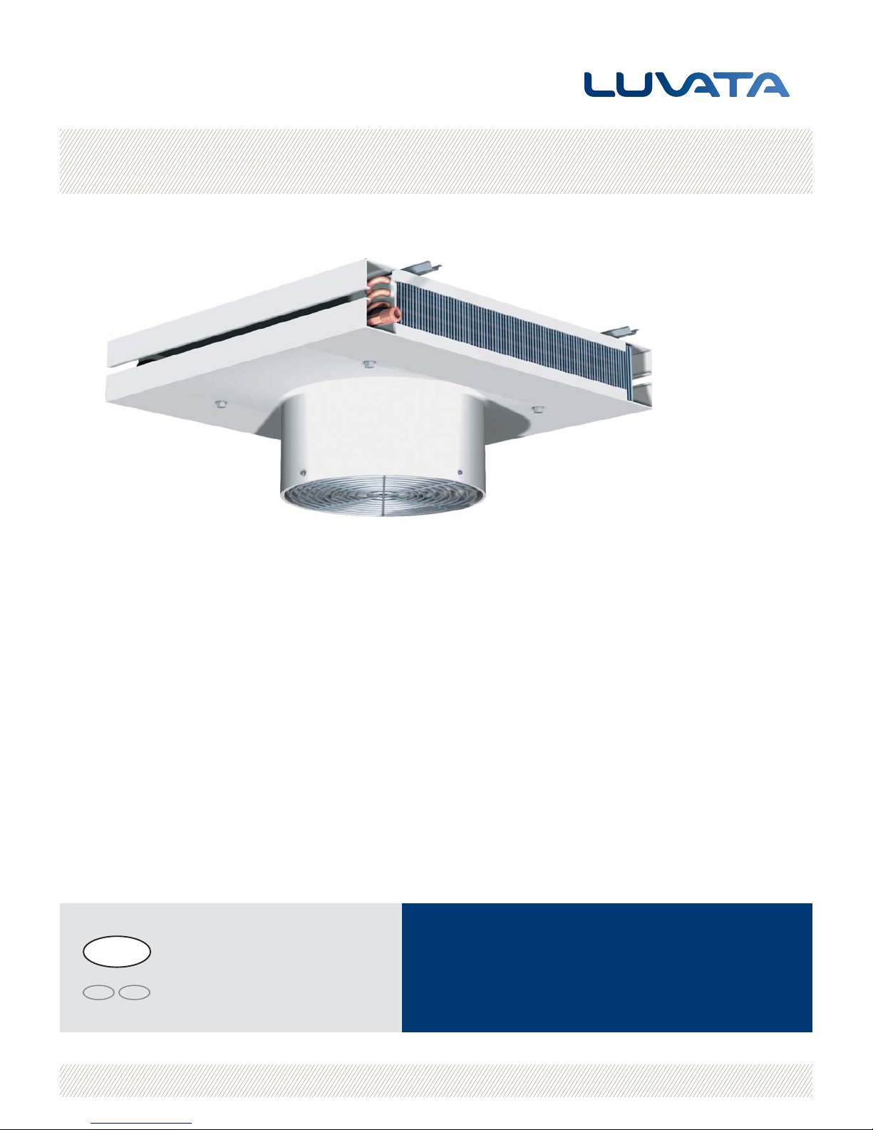
Air heater unit LVD
User’s Guide
About Luvata
Luvata is a world-leader in metal fabrication, component manufacturing and related
engineering and design services. We are committed to partnering with our customers
to help them increase their competitiveness. Our products and services enable our
customers to improve operational efficiency, improve products and reduce tied-up
capital. This focus on our customers’ results, backed by our unfailing reliability, makes
us a partner on which our customers base their future development.
General description
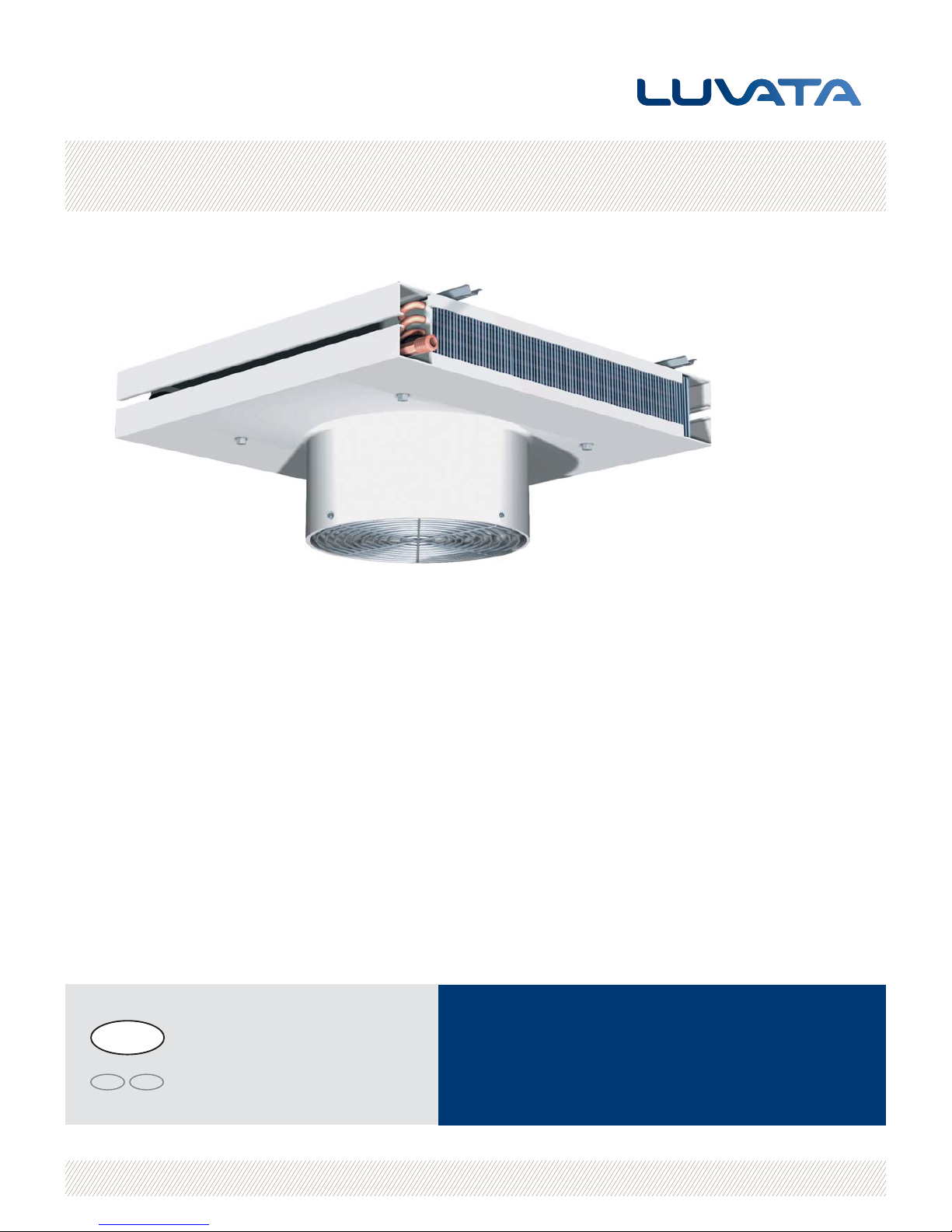
The air heater unit consists of a fan, motor and heat
exchanger and it is used to heat air with water. The water
circulates in the air heater unit’s heat exchanger and
heats the air with the help of the fan. The air heater unit
can be tted with various accessories to control the supply
of heat. Its low external height ensures that it can be
installed in premises with varying roof heights.
www.luvata.com/coiltech1034564 We reserve the right to alter speci cations
SE FI
Translated from the original Swedish version
Page 2
1034564 We reserve the right to alter speci cations
Air heater unit LVD
GB
2
General
• Always read through the entire User’s Guide before
using the product.
• Always position the air heater unit so that it is not
accessible to unauthorised personnel.
• All work on the air heater unit must be carried out by
quali ed personnel with knowledge of the product and
the applicable safety instructions.
During operation, both the air heater unit and the
air it is blowing out can be hot, which can cause
personal injury.
The air heater unit must not be installed in
environ ments where there is an explosion risk.
Data plate
The data plate is located on one of the sides of the air
heater unit and contains information about:
• Order number
• Product code
• Maximum working temperature
• Maximum working pressure
• Test pressure
• Motor data
• Manufacturer
• Year of manufacture
• Net dry weight
• Fluid volume
Operating pressure
The air heater unit may only be used in a system designed
for its maximum working pressure (MPa) and its maximum
temperature (°C). The values are stated on the air heater
unit’s data plate.
Installation and pipe connections
The air heater unit must be permanently installed. Fasteners and brackets must be capable of withstanding the
load of the air heater unit’s total weight (net weight of air
heater unit and uid in air heater unit). The air heater
unit’s pipe connections must not be subjected to the
weight of the connecting pipe system nor to expansion
forces.
NOTE: Loads and impacts on the pipe system can cause
damage to the air heater unit.
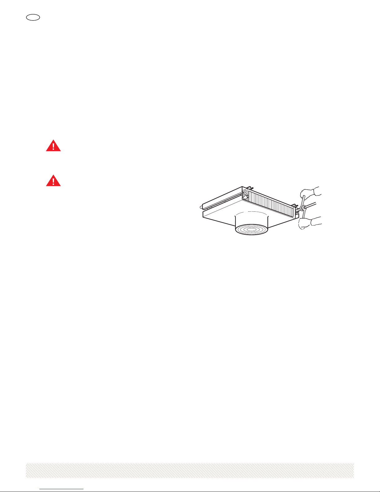
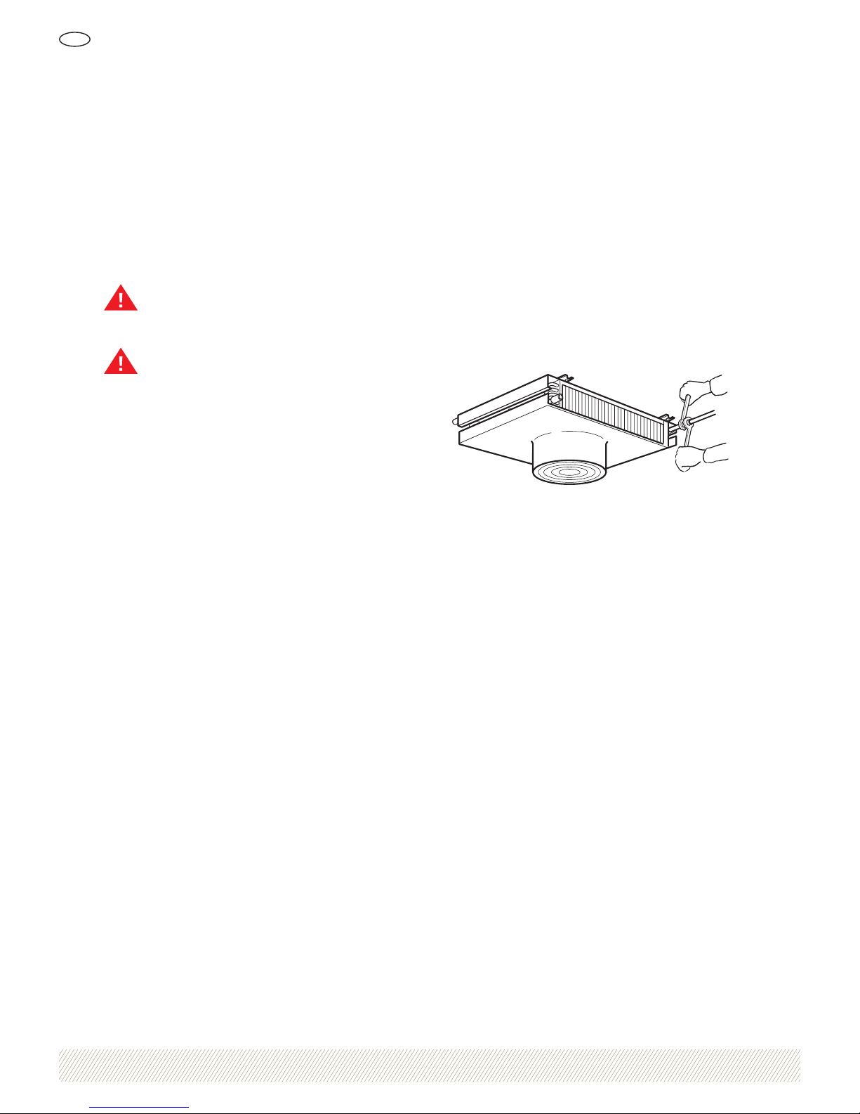
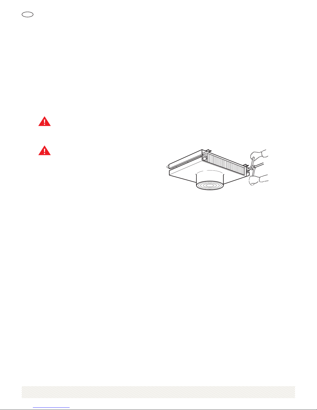
Use a counterhold when tightening the connecting
coupling to prevent the connecting pipes from rotating,
see Figure 1.
Figure 1. Tightening the connecting coupling
Cleaning
Always use environmentally friendly cleaning agents that
will not damage the air heater unit.
Certi cation
Luvata is accredited in accordance with the ISO 9001
quality management system and ISO 14001 environmental management system.
Product description and safety instructions
Page 3
1034564 We reserve the right to alter speci cations
Air heater unit LVD
GB
3
On delivery
The air heater unit is designed to withstand normal loads
during transport. After transport and unloading it is
important to check that no damage has occurred. Check
in particular the ns of the heat exchanger and the outer
casing and connecting pipes of the air heater unit. Any
transport damage should be reported immediately to the
carrier and to Luvata. Also make notes on the consignment note.
Installation and pipe connections
The air heater unit must be permanently installed and
positioned so that the required air supply is obtained.
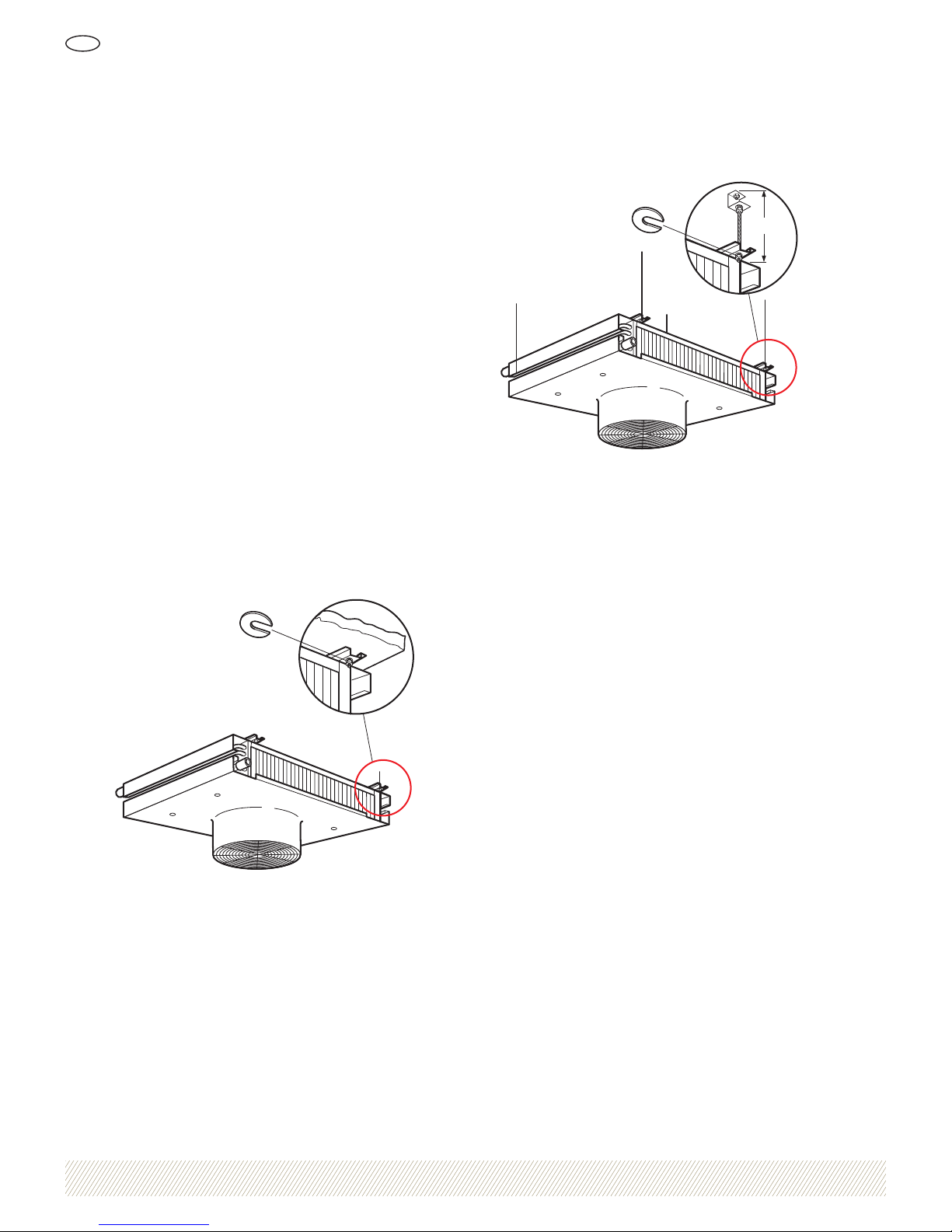
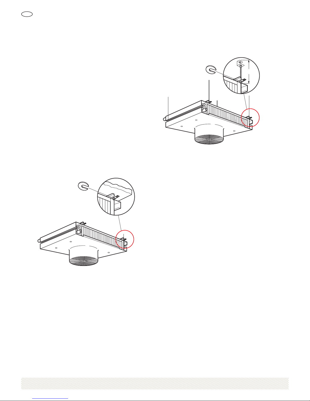
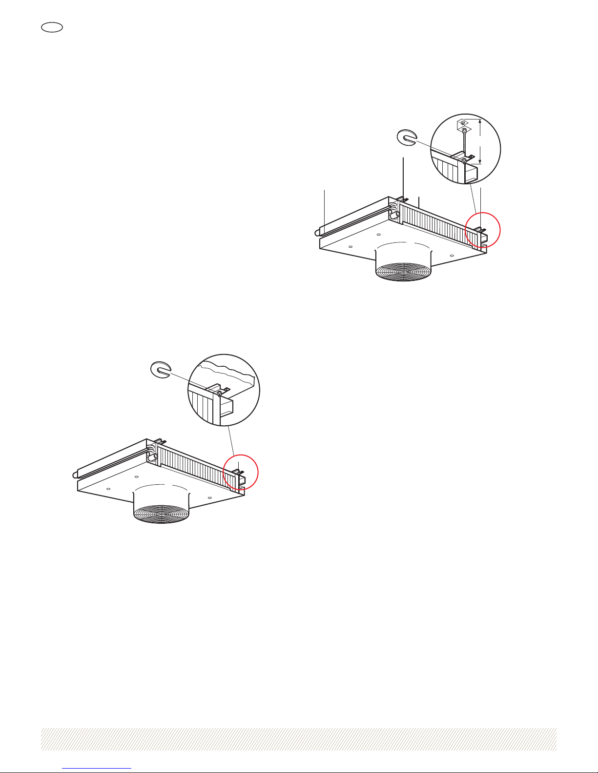
The air heater unit is intended to be installed directly on
the ceiling or by using drop rods (accessory LVDZ-03),
see Figure 2 and Figure 3. Both the air heater unit and
accessories are provided with holes which are designed for
installation.
If air discharge sleeve LVDZ-04 is used, the contact guard
should be tted to it. The air discharge sleeve is tted to
the air heater unit’s fan outlet.
Any pipe connections can be used for the uid connections.
Figure 2. Installation on the ceiling
350 mm
Figure 3. Installation using drop rods
Electrical connection
The fan motor must be connected to a lockable safety
switch. The safety switch must not be used to start and
stop the unit, but it must be started/stopped using other
external equipment.
Ahead of the motor a motor cut-out should be tted which
must not be set higher than the motor’s maximum permitted current. A motor cut-out is not necessary on motors
with an integrated temperature monitor when the temperature monitor is connected.
On delivery the fan motor is connected to a junction box
located on one of the sides of the air heater unit.
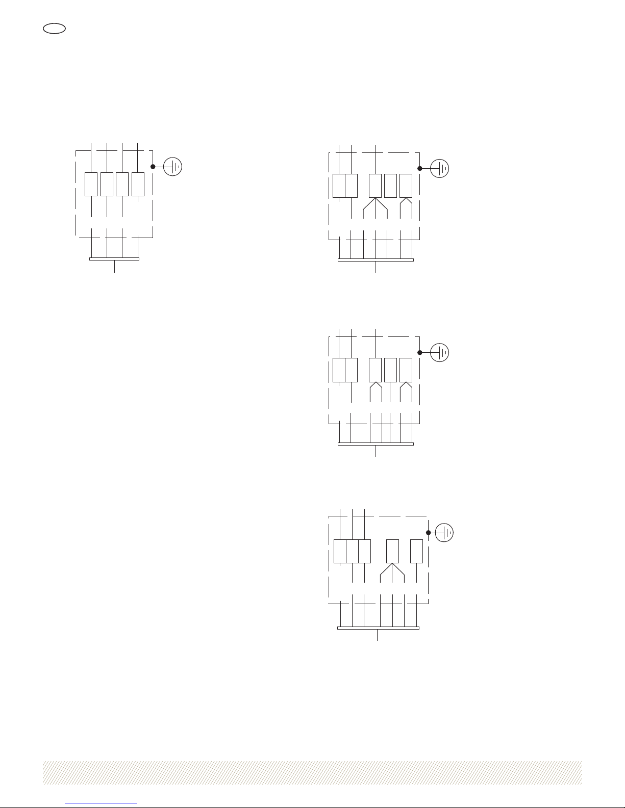
The connecting electrical cable is connected as illustrated
in the wiring diagram in the section headed Connection
diagram. Then check that the fan rotates in the direction
of the rotation arrow. The arrow is located on the outside
of the fan ring.
Dismantling
When dismantling the air heater unit from a system, it
must rst be drained of all liquid.
NOTE: Environmentally hazardous liquids must be
collected in a container and left for disposal/recycling.
Installation
Page 4
1034564 We reserve the right to alter speci cations
Air heater unit LVD
GB
4
Preventive maintenance
The following should be checked regularly to prevent
operational failures:
• Abnormal sounds or vibrations – check motor bearing
and fan impeller.
• Fastening devices – check that all bolted joints are
undamaged.
• Electrical installation – check for any damage and that
the safety switch functions correctly.
• Fin structure – check that it is clean and undamaged.
• Fan impeller – check that it is clean and undamaged.
Fan unit
The fan motors do not require regular maintenance
because they have permanently lubricated bearings.
Cleaning
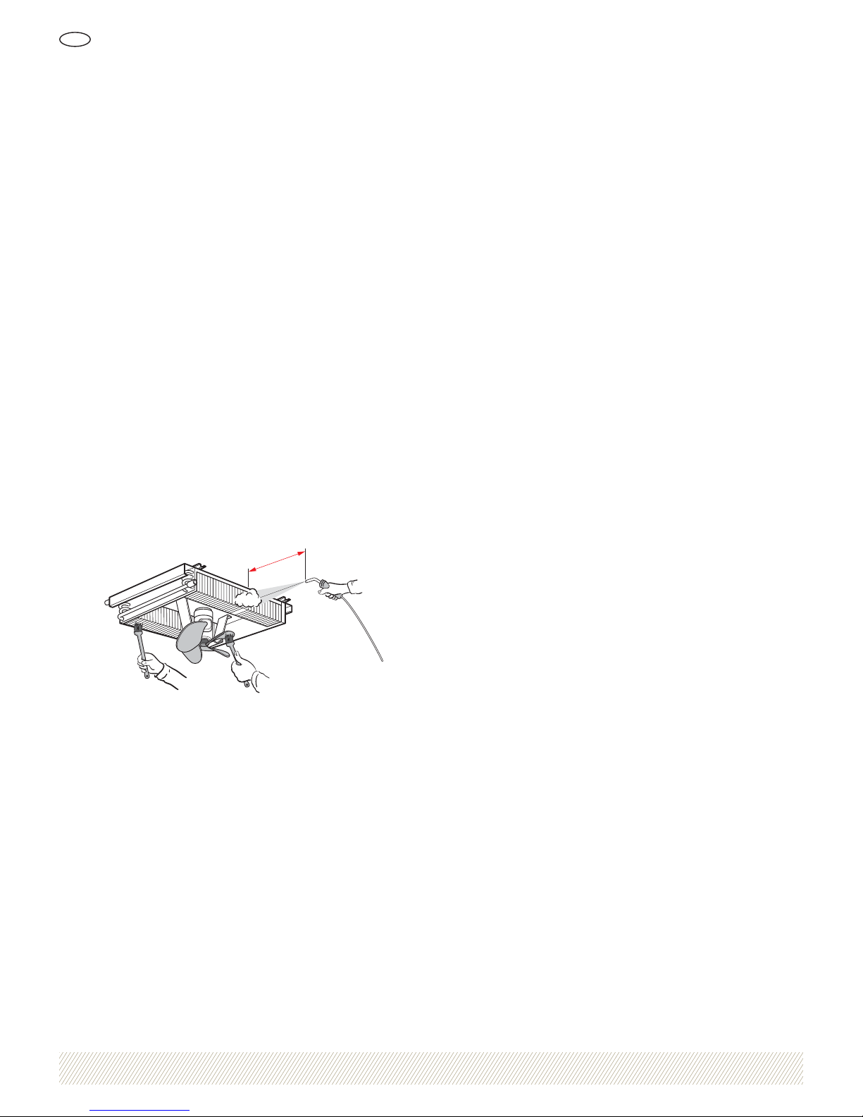
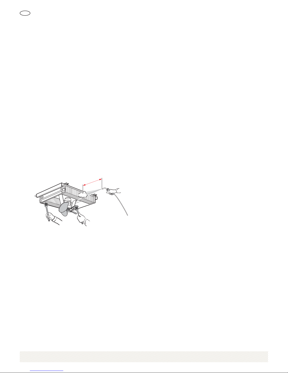
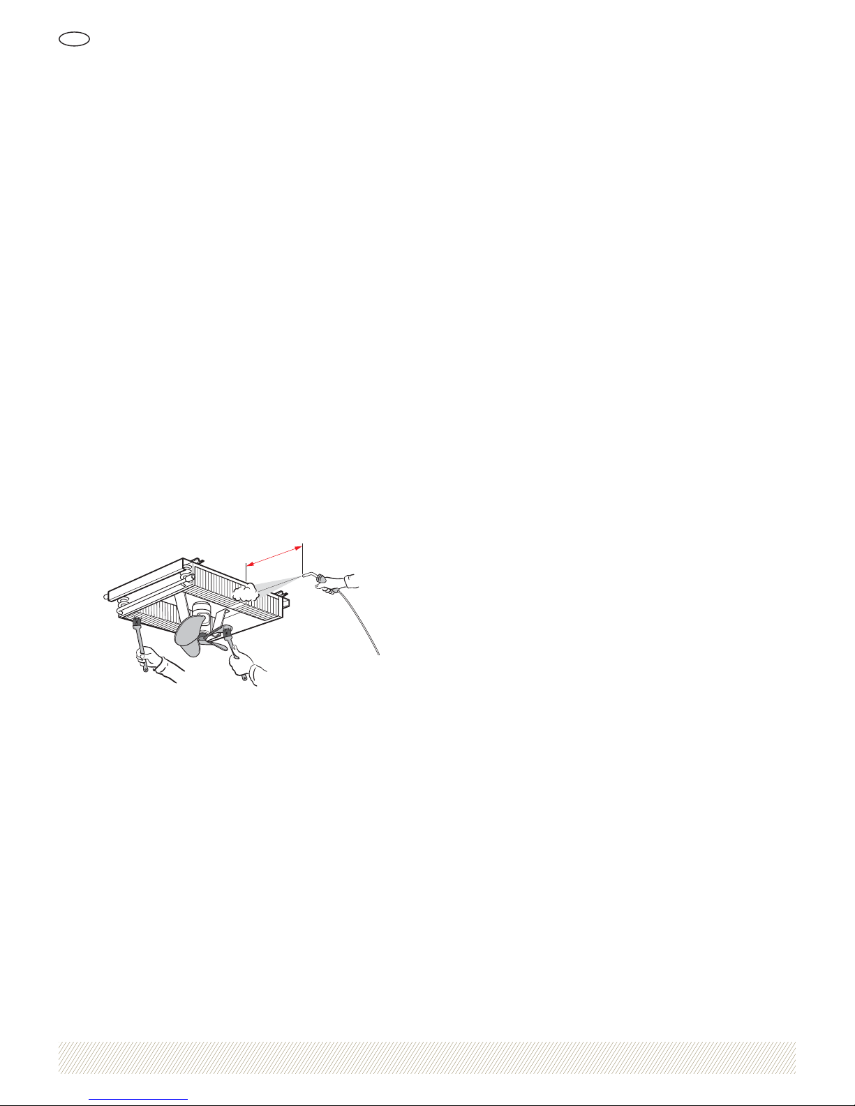
The best method of cleaning the air heater unit’s n heat
exchanger is to use compressed air or a high pressure
washer. The nozzle should always be held at right angles
to the surface of the ns and not closer than 150 mm so
as not to damage the ns, see Figure 4. Fins damaged
during cleaning can be straightened using a n comb
(accessory QLAZ-20).
Min 150 mm
Figure 4. Cleaning the n heat exchanger
When cleaning with compressed air:
1. Switch off the mains supply to the air heater unit.
2. Loosen the four screws (A) and remove the front, see
Figure 5.
3. Set the nozzle at right angles to the surface of the ns
so as not to damage the ns.
When cleaning with a high pressure washer:
1. Switch off the mains supply to the air heater unit.
2. Loosen the four screws (A) and remove the front, see
Figure 5.
3. Cover the motor with plastic to protect the motor from
moisture.
4. Spray environmentally friendly cleaning agent at low
pressure onto the n heat exchanger.
5. High pressure wash with water after 10-12 minutes.
Remember to hold the nozzle at right angles to the
surface of the ns.
6. Check that no remnants of the cleaning agent are left
after cleaning, since they can bind fresh dust.
Spare parts
In installations with very high demands on availability, we
recommend that one motor is kept as a spare part.
NOTE: Motors kept as spare parts should be stored
indoors in dry and dust-free conditions.
NOTE: Only parts and materials recommended by Luvata
are to be used in order for the warranty speci ed in the
order con rmation to be valid.
Maintenance and service
Page 5
1034564 We reserve the right to alter speci cations
Air heater unit LVD
GB
5
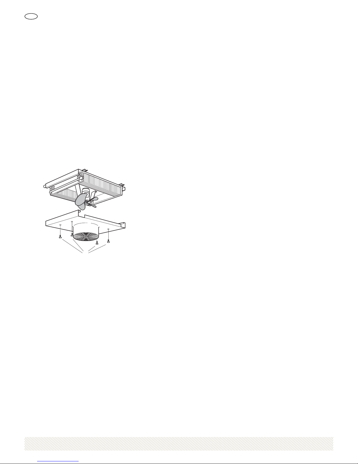
Replacing the motor and fan impeller
1. Switch off the mains supply to the air heater unit and
lock the safety switch in the OFF position.
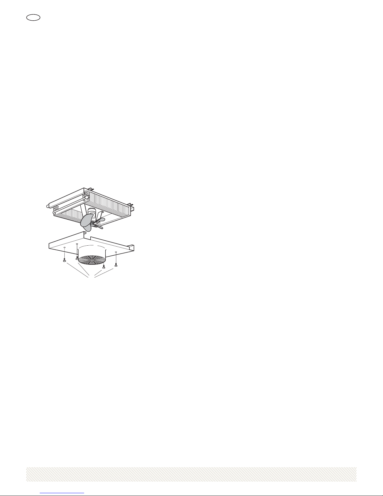
2. Loosen the four screws (A) and remove the front,
see Figure 5.
3. Loosen the locking screw on the fan and dismantle the
fan from the motor.
4. Disconnect the electrical cable from the junction box.
5. Loosen the four screws holding the motor on the motor
mounting and lift off the motor.
6. Install the new fan unit by following the above
instructions in reverse order.
7. Check that the fan impeller is centred in the fan ring
and that the fan rotates in the direction indicated by
the arrow.
8. Start the air heater unit.
A
Figure 5. Removing the front
Risk of freezing
In installations with an ambient temperature of less than
0°C, there is a risk of damage due to freezing if the heat
exchanger becomes too cold. The air heater unit should
be drained of water if the system is not used during the
winter. Use compressed air to blow out any remaining
water when the heat exchanger cannot be fully drained.
The air heater unit does not need to be drained if it is
lled with water containing anti-freeze.
Long-term storage
When the unit is stored for longer than one month, the
following applies:
• Store the air heater unit indoors in the position in
which it is to be installed.
• Cover the air heater unit with reinforced plastic or
some other mechanical protection to prevent contamination and water from penetrating and soiling or
damaging the n structure and fan unit.
• The air heater unit’s pipe connections should be
sealed.
• If the air heater unit is stored in a damp environment,
the surface nish must be checked regularly to ensure
that damage does not occur. Touch up any damage to
paintwork.
Maintenance and service
Page 6
1034564 We reserve the right to alter speci cations
Air heater unit LVD
GB
6
Operating data
Max air temperature around the motor: +70°C
Min air temperature around the motor: -15°C.
Max permitted operating pressure: 1.6 MPa at 100˚C
All heat exchangers are leak-tested under water using dry air.
Motor data
For information, refer to the air heater unit’s data plate.
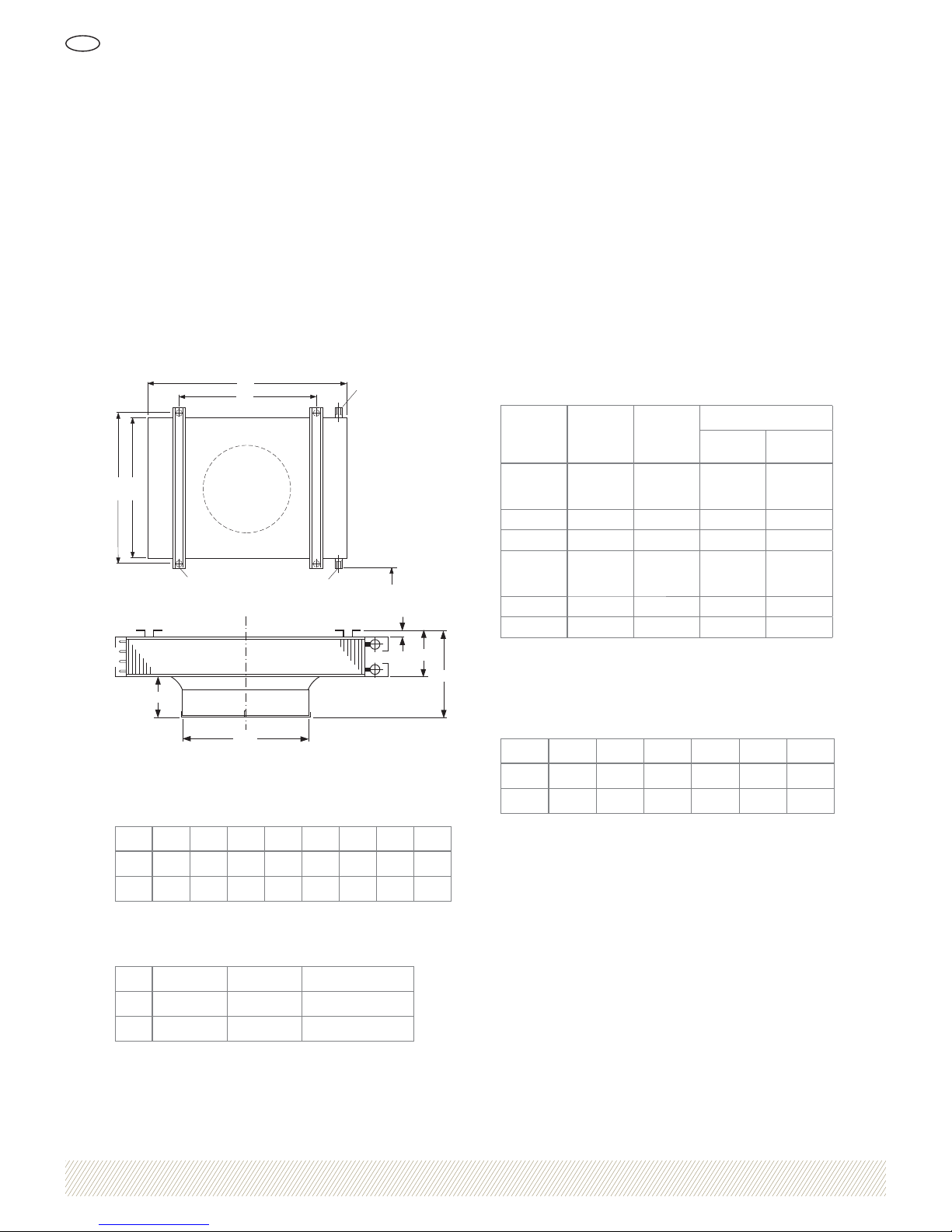
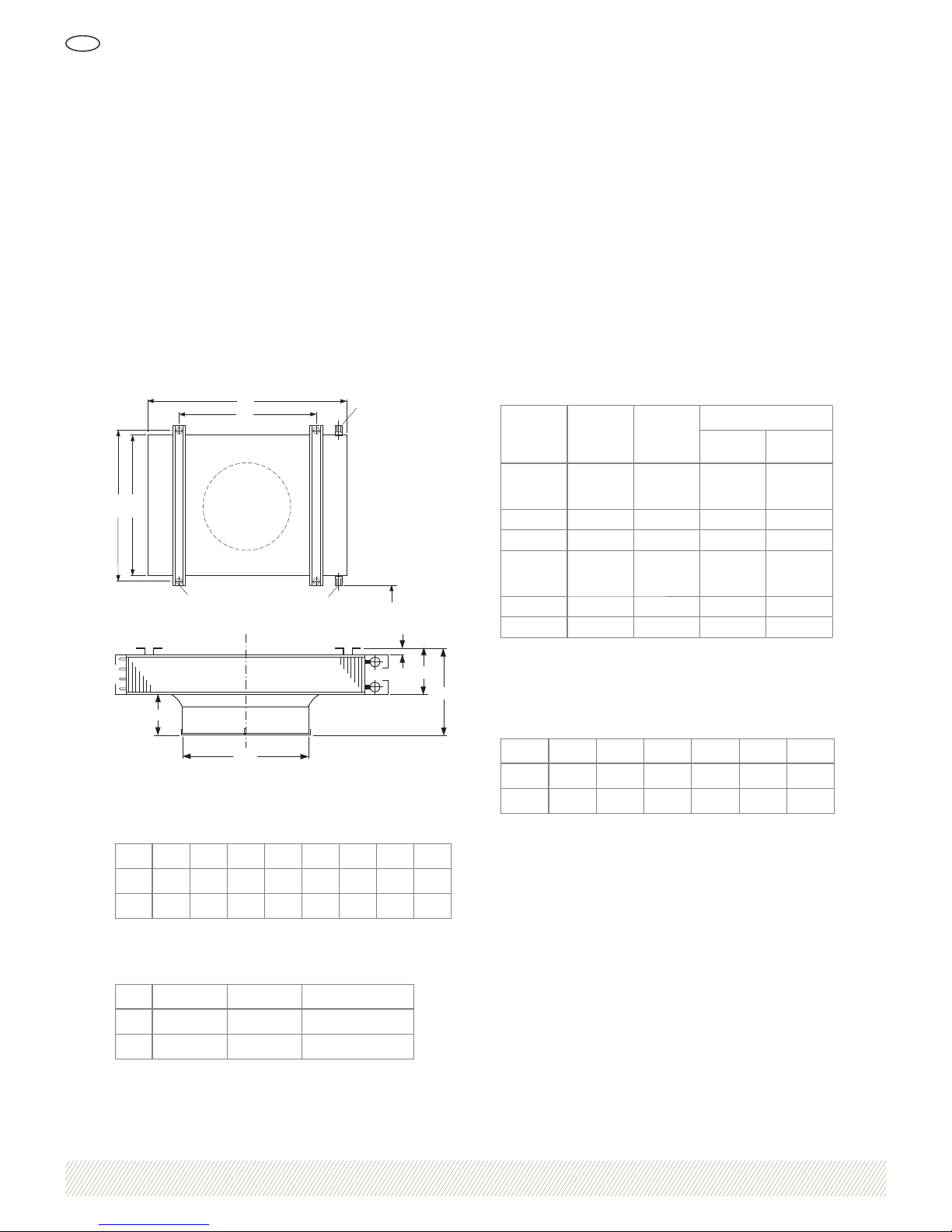
Dimensions, weight and volume
30
Ø 15
CB
A
D
K
K
20
E
F
H
Ø G
Figure 6. Dimensions
Table 1. Dimensions (mm)
LVDV ABCDEFGH
40 930 600 635 760 155 345 406 190
50 1130 700 735 960 220 380 514 160
Table 2. Weight, volume and pipe connections
LVDV Weight (kg) Volume (litres) K (pipe connection)
40 31 1.6 DN 20
50 45 3.8 DN 25
Heat exchanger
The heat exchanger consists of tubes that are mechanically expanded onto the ns. The ns are manufactured
as whole plates without slots to avoid dust and bres
collecting on the n structure.
Fan unit
The fan unit’s motor is a ange motor, journalled on ball
bearings, with a self-resetting thermal cut-out (not on
three phase). The fan impeller has a painted steel hub
and aluminium blades.
Table 3. Technical data, fan unit
LVDV
Rotational
speed (rpm)
Rated output
(kW)
Rated current (A), 50 Hz
Single phase
230 V
Three phase
400 V Y
40-1
1300
1)
900
670
0.15
1.50
1.0
0.7
–
–
–
40-6 920
1)
0.18 – 0.7
40-4 1380
1)
0.18 – 0.7
50-1
900
1)
670
570
0.17
1.7
1.2
0.7
–
–
–
50-6 920
1)
0.18 – 0.7
50-4 1410
1)
0.55 – 1.5
1)
Speed as delivered. Other speeds can be obtained by altering the motor
connections as indicated in the connection diagram, see Figures 8–10.
Table 4. Speed with accessories for voltage control
LVDV 230 V 150 V 130 V 115 V 100 V 80 V
40-1 1300
1)
980
1)
820 690
1)
560 380
50-1 900
1)
770 690
1)
610
1)
510 370
1)
Speed as delivered
Protection classes
Motor: IP55
Junction box: IP44
Technical data
Page 7
1034564 We reserve the right to alter speci cations
Air heater unit LVD
GB
7
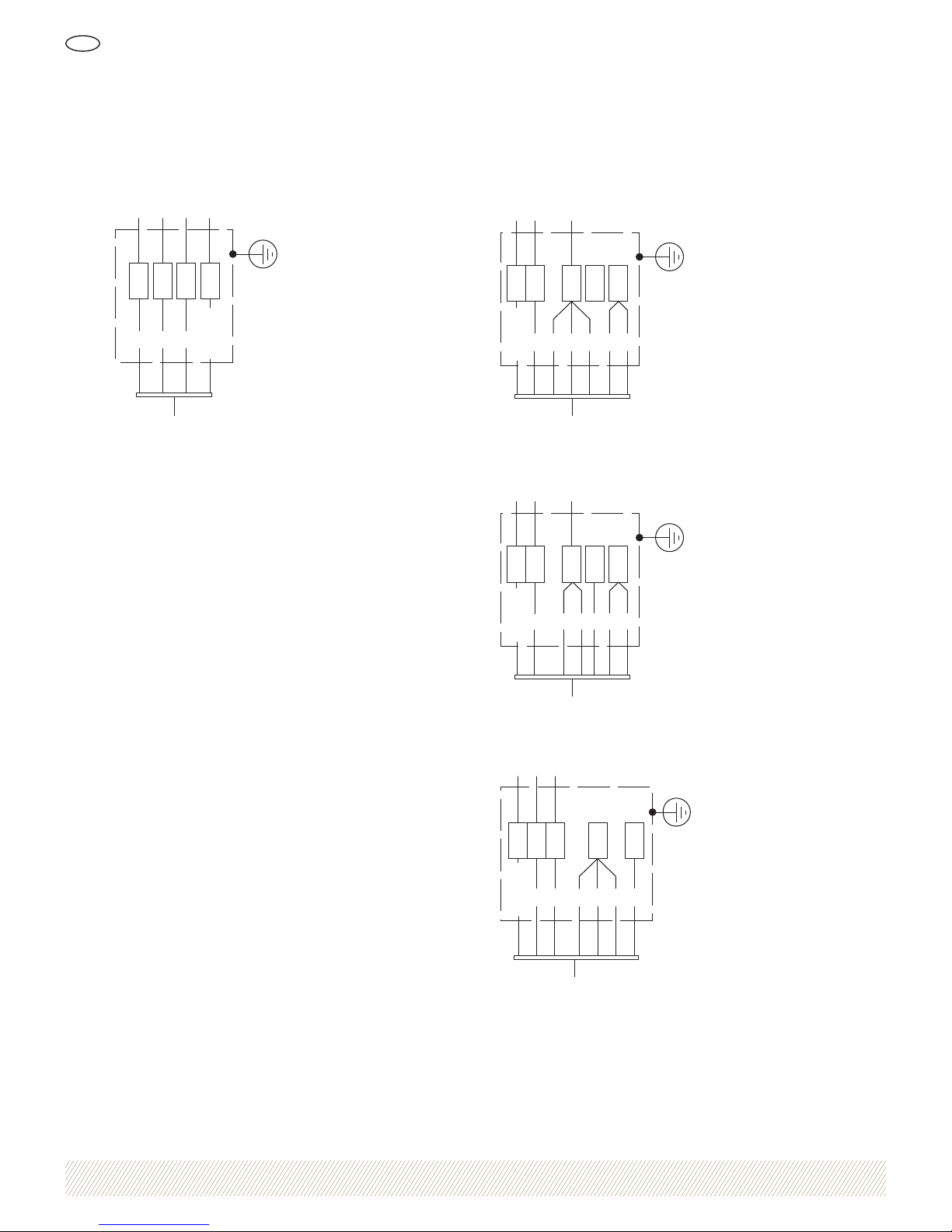
Three phase
R S T PE
12
3
Yellow/
Green
Fan motor
Figure 7. Y-coupling, design as supplied
Single phase with thermal cut-out
PE L N
12345 6
Yellow/
Green
Motor
Figure 8. High speed, design as supplied
12
3456
PE L N
Yellow/
Green
Motor
Figure 9. Intermediate speed
12 34 56
PE L N
Yellow/
Green
Motor
Figure 10. Low speed
Connection diagram
Page 8
Luvata Söderköping AB
SE-614 81 Söderköping, Sweden
Phone +46 121 191 00
Fax +46 121 101 01
www.luvata.com/coiltech
5000-0096 • September 2009
Air heater unit LVD
GB
A COILTECH PRODUCT MANUFACTURED BY LUVATA SÖDERKÖPING AB
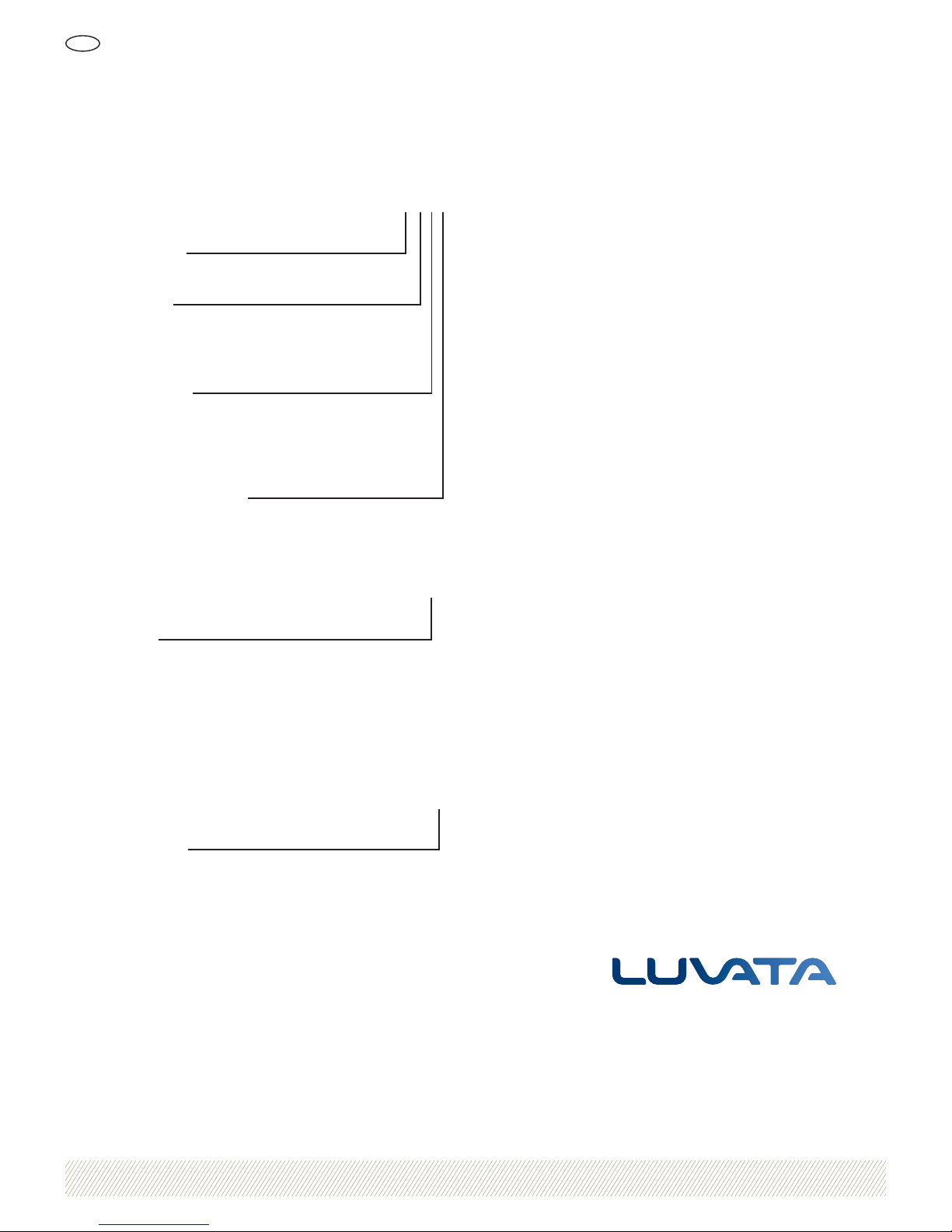
Standard design
Air heater unit LVDV-aa-b-c-d
Size (aa)
40, 50
Motor (b)
1 = 1x230 V
4 = 3x400 V, 4-pin (without controls, c = 0)
6 = 3x400 V, 6-pin (without controls, c = 0)
Control equipment (c)
0 = without controls
A = A box
B = B box
C = C box
Design digit (d)
1 = 2004 –
Control equipment
Air heater unit installation pack LVDZ-a-1
Type (a)
A = A box
B = B box
C = C box
Accessories
Drop rods, set LVDZ-03-1
Air discharge sleeve LVDZ-04-bb
Size (bb)
40, 50
Spare parts for LVDV 40
Fan impeller LVDV-99-01-5
Motor (1x230 V, 3 speeds) LVDV-99-02-12
Motor (3x400 V, 4-pin) LVDV-99-02-14
Motor (3x400 V, 6-pin) LVDV-99-02-16
Contact guard LVDV-99-03-3
Heat exchanger LVDV-99-04-1
Spare parts for LVDV 50
Fan impeller LVDV-99-01-6
Motor (1x230 V, 3 speeds) LVDV-99-02-13
Motor (3x400 V, 4-pin) LVDV-99-02-17
Motor (3x400 V, 6-pin) LVDV-99-02-15
Contact guard LVDV-99-03-4
Heat exchanger LVDV-99-04-2
Product code
Page 9
Luftvärmare LVD
Bruksanvisning
SE
About Luvata
Luvata is a world-leader in metal fabrication, component manufacturing and related
engineering and design services. We are committed to partnering with our customers
to help them increase their competitiveness. Our products and services enable our
customers to improve operational efficiency, improve products and reduce tied-up
capital. This focus on our customers’ results, backed by our unfailing reliability, makes
us a partner on which our customers base their future development.
Generell beskrivning
Luftvärmaren består av äkt, motor och värmeväxlare och
används för att värma luft med vatten. Vattnet cirkulerar i
luftvärmarens värmeväxlare och värmer luften med hjälp
av äkten. Luftvärmaren kan förses med ett ertal tillbehör för att reglera värmetillförseln. Dess låga bygghöjd
möjliggör installation i lokaler med varierande takhöjd.
www.luvata.com/coiltech1034564 Rätten till ändringar förbehålls
Bruksanvisning i original
GB FI
Page 10
1034564 Rätten till ändringar förbehålls
Luftvärmare LVD
SE
10
Allmänt
• Läs alltid hela bruksanvisningen innan någon hantering
av produkten utförs.
• Placera alltid luftvärmaren oåtkomlig för obehöriga.
• Allt arbete på luftvärmaren ska utföras av utbildad
personal som har kunskap om produkten och gällande
säkerhetsföreskrifter.
Vid drift kan både luftvärmaren och den utblå-
sande luften vara varm, vilket kan orsaka personskada.
Luftvärmaren får inte installeras i miljöer med
explosionsrisk.
Dataskylt
Dataskylten är placerad på en av luftvärmarens sidor och
innehåller information om:
• Ordernummer
• Produktkod
• Maximal arbetstemperatur
• Maximalt arbetstryck
• Provtryck
• Motordata
• Tillverkare
• Tillverkningsår
• Torrvikt
• Vätskevolym
Drifttryck
Luftvärmaren får endast användas i ett system som är
säkrat för det maximala arbetstrycket (MPa) och den
maximala temperaturen (°C). Värdena nns angivna på
luftvärmarens dataskylt.
Montering och röranslutningar
Luftvärmaren ska vara fast förankrad. Fästen och konsoler
ska tåla belastningen av luftvärmarens totala vikt (luftvärmarens torrvikt samt vätskan i luftvärmaren). Luftvärmarens röranslutningar får inte belastas med det
anslutande rör systemets egenvikt eller expansionskrafter.
OBS! Belastning och slag på rörsystemet kan orsaka
skador på luftvärmaren.
Vid åtdragning av anslutningskopplingen ska mothåll användas för att anslutningsrören inte ska vridas, se Figur 1.
Figur 1. Åtdragning av anslutningskoppling
Rengöring
Använd alltid miljövänliga rengöringsmedel som ej skadar
luftvärmaren.
Certi ering
Luvata är certi erat enligt ledningssystem för kvalitet ISO
9001 samt miljöledningssystem ISO 14001.
Produktbeskrivning och säkerhetsföreskrifter
Page 11
1034564 Rätten till ändringar förbehålls
Luftvärmare LVD
SE
11
Vid leverans
Luftvärmaren är konstruerad för att tåla normala laster under transport. Efter transport och lossning är det viktigt att
kontrollera att inga skador uppstått. Kontrollera särskilt
värmeväxlarens lamellyta samt luftvärmarens hölje och
anslutningsrör. Eventuella transportskador ska omedelbart
anmälas till fraktbolaget och Luvata. Gör även en anmärkning på fraktsedeln.
Montering och röranslutningar
Luftvärmaren ska vara fast förankrad och placeras så att
nödvändig luftförsörjning erhålls. Luftvärmaren är avsedd
att monteras direkt mot tak eller i takpendlar (tillbehör
LVDZ-03), se Figur 2 och Figur 3. Både luftvärmaren
och tillbehören är försedda med hål som är avsedda för
monteringen.
Om utloppsstos LVDZ-04 används ska beröringsskyddet
monteras på denna. Utlopps stosen monteras på luftvärmarens äkt utlopp.
Vätskeanslutning utförs på valfri röranslutning.
Figur 2. Montering mot tak
350 mm
Figur 3. Montering i takpendlar
Elektrisk anslutning
Fläktmotorn ska kopplas till en låsbar säkerhetsbrytare.
Säkerhetsbrytaren får inte användas för start/stopp, det
ska utföras genom annan extern utrustning.
Motorn ska föregås av ett motorskydd som inte får vara
inställt högre än motorns maximalt tillåtna ström. På
motorer med inbyggd temperaturvakt behövs inget motorskydd om temperaturvakten är inkopplad.
Fläktmotorn är vid leverans kopplad till en kopplingsdosa
som är placerad på en av luftvärmarens sidor.
Anslutande elkabel ska kopplas enligt scheman i kapitel
Anslutningsschema. Kontrollera därefter att äkten roterar
i rotationspilens riktning. Pilen är placerad på äktringens
utsida.
Demontering
Vid demontering av luftvärmaren ur ett system ska luftvärmaren först tömmas på vätska.
OBS! Miljöfarliga vätskor ska samlas upp i kärl och
lämnas för deponering/återvinning.
Installation
Page 12
1034564 Rätten till ändringar förbehålls
Luftvärmare LVD
SE
12
Förebyggande underhåll
Följande bör kontrolleras regelbundet för att undvika
driftsstörningar:
• Missljud eller vibrationer – kontrollera motorlager och
äkthjul.
• Fästelement – kontrollera att samtliga skruvförband är
oskadade.
• Elinstallation – kontrollera ev. skador samt säkerhetsbrytarens funktion.
• Lamellkropp – kontrollera att den är ren och oskadad.
• Fläkthjul – kontrollera att det är rent och oskadat.
Fläktenhet
Fläktmotorerna kräver inget regelbundet underhåll
eftersom de har permanentsmorda lager.
Rengöring
Luftvärmarens lamellvärmeväxlare rengörs bäst med
tryckluft eller högtryckstvätt. Munstycket ska alltid hållas
vinkelrätt mot lamellytan och ej närmare än 150 mm för
att inte skada lamellerna, se Figur 4. Lameller som skadas
vid rengöring kan riktas med hjälp av en lamellkam (tillbehör QLAZ-20).
Min 150 mm
Figur 4. Rengöring av lamellvärmeväxlare
Vid rengöring med tryckluft:
1. Bryt strömmen till luftvärmaren.
2. Lossa de fyra skruvarna (A) och ta bort fronten, se
Figur 5.
3. Vinkla munstycket vinkelrätt mot lamellytan för att inte
skada lamellen.
Vid rengöring med högtryckstvätt:
1. Bryt strömmen till luftvärmaren.
2. Lossa de fyra skruvarna (A) och ta bort fronten, se
Figur 5.
3. Täck motorn med plast för att skydda motorn mot fukt.
4. Spruta miljövänligt rengöringsmedel under lågt tryck på
lamellvärmeväxlaren.
5. Högtryckstvätta med vatten efter 10–12 minuter.
Tänk på att hålla munstycket vinkelrätt mot lamellytan.
6. Kontrollera så att inga rester från rengöringsmedlet
nns kvar efter tvätt då de kan binda nytt damm.
Reservdelar
På anläggningar med mycket höga krav på tillgänglighet
rekommenderas att en motor hålls som reservdel.
OBS! Vid reservdelshållning av motor ska den förvaras
inomhus under torra och dammfria förhållanden.
OBS! Endast detaljer och material föreslagna av Luvata
får användas för att angivna garantier enligt orderbekräftelsen ska gälla.
Underhåll och service
Page 13
1034564 Rätten till ändringar förbehålls
Luftvärmare LVD
SE
13
Byte av motor och äkthjul
1. Bryt strömmen till luftvärmaren och lås säkerhetsbrytaren i läge OFF.
2. Lossa de fyra skruvarna (A) och ta bort fronten, se
Figur 5.
3. Lossa låsskruven på äkten och demontera äkten från
motorn.
4. Lossa elkabeln från kopplingsdosan.
5. Lossa de fyra skruvarna som håller motorn i motorfästet
och lyft bort motorn.
6. Montera den nya motorn genom att följa ovanstående
punkter i omvänd ordning.
7. Kontrollera att äkthjulet är centrerat i äktringen och
att äkten roterar i rotationspilens riktning.
8. Starta luftvärmaren.
A
Figur 5. Borttagning av front
Frysrisk
På anläggningar med omgivningstemperatur under 0 ˚C
nns det risk för sönderfrysning om värmeväxlaren blir för
kall. Luftvärmaren bör tömmas på vatten om anläggningen
inte används vintertid. Använd tryckluft för att blåsa ur
eventuellt kvarvarande vatten då värmeväxlaren inte är
helt avtappningsbar. Luftvärmaren behöver dock inte tömmas om den är fylld med vatten med frostskyddsmedel.
Långtidslagring
Vid lagring längre än en månad gäller följande:
• Förvara luftvärmaren inomhus i den position som den
ska installeras.
• Täck luftvärmaren med armerad plast eller annat
mekaniskt skydd för att förhindra att föroreningar och
vatten tränger in och smutsar ner eller skadar lamellkroppen och äktenheten.
• Luftvärmarens röranslutningar ska vara blindade.
• Om luftvärmaren förvaras i fuktig miljö måste
yt behandlingen kontrolleras regelbundet så att inga
skador uppstått. Bättringsmålning av skador får utföras.
Underhåll och service
Page 14
1034564 Rätten till ändringar förbehålls
Luftvärmare LVD
SE
14
Driftdata
Max lufttemperatur runt motorn: +70 ˚C
Min lufttemperatur runt motorn: -15 ˚C
Max tillåtet drifttryck: 1,6 MPa vid 100 ˚C
Samtliga värmeväxlare är läcktestade med torr luft under
vatten.
Motordata
För information, se luftvärmarens dataskylt.
Dimensioner, vikt och volym
30
Ø 15
CB
A
D
K
K
20
E
F
H
Ø G
Figur 6. Dimensioner
Tabell 1. Dimensioner (mm)
LVDV ABCDEFGH
40 930 600 635 760 155 345 406 190
50 1130 700 735 960 220 380 514 160
Tabell 2. Vikt, volym och röranslutningar
LVDV Vikt (kg) Volym (liter) K (röranslutning)
40 31 1,6 DN 20
50 45 3,8 DN 25
Värmeväxlare
Värmeväxlaren består av tuber som är mekaniskt expanderande mot lameller. Lamellerna är tillverkade som hela
plåtar utan slitsar för att undvika att damm och brer
fastnar i lamellkroppen.
Fläktenhet
Fläktenhetens motor är en kullagrad änsmotor med
termo kontakt (ej 3-fas) med automatisk åter ställning.
Fläkthjulet har ett nav av målat stål och blad av
aluminium.
Tabell 3. Tekniska data, äktenhet
LVDV
Varvtal
(rpm)
Märk effekt
(kW)
Märkström (A), 50 Hz
1-fas
230 V
3-fas
400 V Y
40-1
1300
1)
900
670
0,15
1,50
1,0
0,7
–
–
–
40-6 920
1)
0,18 – 0,7
40-4 1380
1)
0,18 – 0,7
50-1
900
1)
670
570
0,17
1,7
1,2
0,7
–
–
–
50-6 920
1)
0,18 – 0,7
50-4 1410
1)
0,55 – 1,5
1)
Varvtal i leveransutförande. Övriga varvtal fås genom omkoppling enligt
anslutningsscheman, se Figur 8–10.
Tabell 4. Varvtal med tillbehör för spänningsstyrning
LVDV 230 V 150 V 130 V 115 V 100 V 80 V
40-1 1300
1)
980
1)
820 690
1)
560 380
50-1 900
1)
770 690
1)
610
1)
510 370
1)
Varvtal i leveransutförande
Kapslingsklasser
Motor: IP55
Kopplingsdosa: IP44
Tekniska data
Page 15
1034564 Rätten till ändringar förbehålls
Luftvärmare LVD
SE
15
Trefas
R S T PE
12
3
Gul/Grön
Motor
Figur 7. Y-koppling, leveransutförande
Enfas med termokontakt
PE L N
12345 6
Gul/Grön
Motor
Figur 8. Högfart, leveransutförande
12
3456
PE L N
Gul/Grön
Motor
Figur 9. Mellanfart
12 34 56
PE L N
Gul/Grön
Motor
Figur 10. Lågfart
Anslutningsschema
Page 16
Luvata Söderköping AB
SE-614 81 Söderköping, Sweden
Phone +46 121 191 00
Fax +46 121 101 01
www.luvata.com/coiltech
5000-0096 • September 2009
Luftvärmare LVD
SE
EN COILTECH PRODUKT TILLVERKAD AV LUVATA SÖDERKÖPING AB
Standardutförande
Luftvärmare LVDV-aa-b-c-d
Storlek (aa)
40, 50
Motor (b)
1 = 1x230 V
4 = 3x400 V, 4-pol (utan reglering, c = 0)
6 = 3x400 V, 6-pol (utan reglering, c = 0)
Reglering (c)
0 = utan reglering
A = A-box
B = B-box
C = C-box
Konstruktionssiffra (d)
1 = 2004 –
Styr- och reglerutrustning
Installationspaket för luftvärmare LVDZ-a-1
Typ (a)
A = A-box
B = B-box
C = C-box
Tillbehör
Takpendel, sats LVDZ-03-1
Utloppsstos LVDZ-04-bb
Storlek (bb)
40, 50
Reservdelar till LVDV 40
Fläkthjul LVDV-99-01-5
Motor (1x230 V, 3 hastigheter) LVDV-99-02-12
Motor (3x400 V, 4-polig) LVDV-99-02-14
Motor (3x400 V, 6-polig) LVDV-99-02-16
Beröringsskydd LVDV-99-03-3
Värmeväxlare LVDV-99-04-1
Reservdelar till LVDV 50
Fläkthjul LVDV-99-01-6
Motor (1x230 V, 3 hastigheter) LVDV-99-02-13
Motor (3x400 V, 4-polig) LVDV-99-02-17
Motor (3x400 V, 6-polig) LVDV-99-02-15
Beröringsskydd LVDV-99-03-4
Värmeväxlare LVDV-99-04-2
Produktkod
Page 17
FI
GB SE
Ilmanlämmitin LVD
About Luvata
Luvata is a world-leader in metal fabrication, component manufacturing and related
engineering and design services. We are committed to partnering with our customers
to help them increase their competitiveness. Our products and services enable our
customers to improve operational efficiency, improve products and reduce tied-up
capital. This focus on our customers’ results, backed by our unfailing reliability, makes
us a partner on which our customers base their future development.
Yleinen kuvaus
Ilmanlämmittimeen kuuluu puhallin, moottori ja lämmönvaihdin, ja sitä käytetään ilman lämmittämiseen vedellä.
Vesi kiertää ilmanlämmittimen lämmönvaihtimessa ja
lämmittää ilman puhaltimen avulla. Ilmanlämmitin
voidaan varustaa useilla lisävarusteilla lämmöntuoton
säätämiseksi. Matalan rakenteensa vuoksi lämmitin
voidaan asentaa harjakorkeudeltaan erilaisiin tiloihin.
www.luvata.com/coiltech1034564 Oikeus muutoksiin pidätetään
Käyttöohje
Käännös ruotsalaisesta alkuperäisversiosta
Page 18
1034564 Oikeus muutoksiin pidätetään
Ilmanlämmitin LVD
FI
18
Yleistä
• Tutustu aina koko käyttöohjeeseen ennen tuotteen
käsittelyä.
• Sijoita ilmanlämmitin aina niin, ettei se ole asiattomien
ulottuvilla.
• Vain tehtävään koulutettu henkilöstö, joka tuntee tuotteen ja voimassa olevat turvamääräykset, saa suorittaa
töitä ilmanlämmittimessä.
Sekä ilmanlämmitin että sen puhaltama ilma
voivat olla käytön aikana lämpimiä, mikä voi
aiheuttaa loukkaantumisia.
Älä asenna ilmanlämmitintä räjähdysalttiiseen
ympäristöön.
Kojekilpi
Kojekilpi sijaitsee ilmanlämmittimen toisella sivulla, ja
siinä on seuraavat tiedot:
• Tilausnumero
• Tuotekoodi
• Maksimikäyttölämpötila
• Maksimikäyttöpaine
• Koepaine
• Moottoritiedot
• Valmistaja
• Valmistusvuosi
• Kuivapaino
• Nestetilavuus
Käyttöpaine
Ilmanlämmitintä saa ainoastaan käyttää järjestelmissä,
jotka varmasti kestävät sekä maksimikäyttöpaineen (MPa)
että maksimilämpötilan (°C). Kyseiset arvot on merkitty
ilmanlämmittimen kojekilpeen.
Asennus ja putkiyhteet
Ilmanlämmitin on kiinnitettävä huolella paikalleen. Kannakkeiden tulee olla riittävän tukevia kestämään ilmanlämmittimen kokonaispainon (ilmanlämmittimen kuivapainon ja sen sisältämän nesteen painon). Ilmanlämmittimen
putkiyhteitä ei saa kuormittaa liitettävän putkijärjestelmän
omapainolla eikä myöskään putkijärjestelmän laajenemisvoimilla.
HUOM! Kuormitus ja iskut saattavat vaurioittaa ilmanläm-
mitintä.
Liittimiä kiristettäessä tulee käyttää vastinta, jotta putkiyhteet eivät vääntyisi, ks. Kuva 1.
Kuva 1. Liittimen kiristys
Puhdistus
Käytä ainoastaan ympäristöä säästäviä puhdistusaineita,
jotka eivät vaurioita ilmanlämmitintä.
Serti ointi
Luvata on serti oitu laadunjohtamisjärjestelmän ISO
9001 sekä ympäristöjohtamisjärjestelmän ISO 14001
mukaisesti.
Tuotteen kuvaus ja turvamääräykset
Page 19
1034564 Oikeus muutoksiin pidätetään
Ilmanlämmitin LVD
FI
19
Kuljetus
Ilmanlämmitin on suunniteltu kestämään normaaleja
kuljetuksen aikaisia kuormituksia. Tarkasta, ettei kuljetuksen ja sen vastaanoton yhteydessä ole syntynyt vaurioita.
Tarkasta erityisesti lämmönvaihtimen lamellipinnat sekä
ilmanlämmittimen kotelo ja putkiyhteet. Mahdollisista
kuljetusvaurioista on ilmoitettava välittömästi kuljetusliikkeelle ja Luvatalle. Tee niistä myös huomautus rahtikirjaan.
Asennus ja putkiyhteet
Ilmanlämmitin on kiinnitettävä huolella ja sijoitettava
niin, että saadaan hyvä ilmankierto. Ilmanlämmitin on
suunniteltu asennettavaksi kattoon tai kattoripustimiin
(lisävaruste LVDZ-03), ks. Kuva 2 ja Kuva 3. Ilmanlämmittimessä ja lisävarusteissa on reiät asennusta varten.
Kosketussuoja asennetaan jatko-osaan LVDZ-04, mikäli
sellaista käytetään. Jatko-osa asennetaan ilmanlämmittimen puhaltimen ulostuloaukkoon.
Nestepuolen liitäntä voidaan kytkeä valinnaiseen putkiyhteeseen.
Kuva 2. Asennus kattoon
350 mm
Kuva 3. Asennus kattoripustimiin
Sähköasennus
Puhaltimen moottori tulee kytkeä lukittavaan turvakatkaisimeen. Turvakatkaisinta ei saa käyttää lämmittimen käynnistämiseen tai pysäyttämiseen. Käynnistys ja pysäytys
tulee suorittaa jollakin muulla ulkopuolisella kytkimellä.
Moottoriin on asennettava moottorisuoja, joka rajoittuu
moottorin suurimpaan sallittuun virtaan. Sisäänrakennetuilla lämpövahdeilla varustetuissa moottoreissa moottorisuojaa ei tarvita, mikäli lämpövahti on kytketty käyttöön.
Puhallinmoottori on valmiiksi kytketty toimitukseen sisältyvään kytkentärasiaan, joka sijaitsee ilmanlämmittimen
sivuilla.
Käytettävä sähköjohto kytketään kappaleessa Kytkentäkaavio olevien kaavioiden mukaisesti. Kun puhaltimen
moottorin sähkökytkentä on tehty, tarkista, että puhallin
pyörii pyörimissuuntaa osoittavan nuolen mukaiseen suuntaan. Nuoli on merkitty puhallinrenkaan ulkolaitaan.
Irrotus
Ilmanlämmitintä järjestelmästä irrotettaessa on tärkeää,
että ilmanlämmittimessä oleva neste tyhjennetään.
HUOM! Ympäristölle haitalliset nesteet on kerättävä
astiaan ja jätettävä jätteenkäsittely-/kierrätyslaitokseen.
Asennus
Page 20
1034564 Oikeus muutoksiin pidätetään
Ilmanlämmitin LVD
FI
20
Ennakoiva kunnossapito
Seuraavat asiat tulee tarkistaa säännöllisesti toimintahäiriöiden välttämiseksi:
• Vieraat äänet tai tärinä – tarkasta moottorin laakerit ja
puhaltimen pyörä.
• Kiinnitysosat – tarkista, ettei mikään ruuviliitos ole
viallinen.
• Sähköasennukset – tarkista mahdolliset vauriot sekä
turvakatkaisimen toiminta.
• Lamellirunko – tarkasta, että se on puhdas ja ehjä.
• Puhaltimen pyörä – tarkasta, että se on puhdas ja ehjä.
Puhallinyksikkö
Puhaltimen moottoreissa on kestovoidellut laakerit eivätkä
ne vaadi säännöllistä kunnossapitoa.
Puhdistus
Ilmanlämmittimen lamellilämmönvaihdin puhdistetaan
parhaiten paineilmalla tai suurpainepesurilla. Pidä
suuttimia aina kohtisuorassa lamellipintaan nähden ja
vähintään 150 mm:n päässä pinnasta lamellien vaurioitumisen estämiseksi, ks. Kuva 4. Puhdistuksen yhteydessä
vääntyneet lamellit voidaan suoristaa lamellikammalla
(lisävaruste QLAZ-20).
Väh.
150 mm
Kuva 4. Lamellilämmönvaihtimen puhdistus
Puhdistaminen paineilmalla:
1. Katkaise virta ilmanlämmittimestä.
2. Irrota neljä ruuvia (A) ja irrota etuosa, ks. Kuva 5.
3. Pidä suutin kohtisuorassa lamellipintaan nähden lamellin vaurioitumisen estämiseksi.
Puhdistaminen suurpainepesurilla:
1. Katkaise virta ilmanlämmittimestä.
2. Irrota neljä ruuvia (A) ja irrota etuosa, ks. Kuva 5.
3. Suojaa moottori kosteudelta peittämällä se muovilla.
4. Ruiskuta lämmönvaihtimen kaikille pinnoille ympäristöä säästävää puhdistusainetta.
5. Pese pinnat noin 10–12 minuutin kuluttua suurella
paineella.
On tärkeää pitää suutin suorassa kulmassa lamellipintaa
vasten.
6. Pintaan ei saa pesun jälkeen jäädä jäänteitä puhdistusaineista, koska ne keräävät pölyä.
Varaosat
Vaativissa laitoksissa suositellaan yhden moottorin pitämistä varaosana.
HUOM! Varaosana toimivaa moottoria tulee säilyttää kui-
vissa ja pölyttömissä sisätiloissa.
HUOM! Tilausvahvistuksessa mainitut takuut ovat voi-
massa vain Luvatan suosittelemia osia ja materiaaleja
käytettäessä.
Kunnossapito ja huolto
Page 21
1034564 Oikeus muutoksiin pidätetään
Ilmanlämmitin LVD
FI
21
Moottorin ja puhaltimen pyörän vaihto
1. Katkaise virta ilmanlämmittimestä ja lukitse turvakatkaisin asentoon OFF.
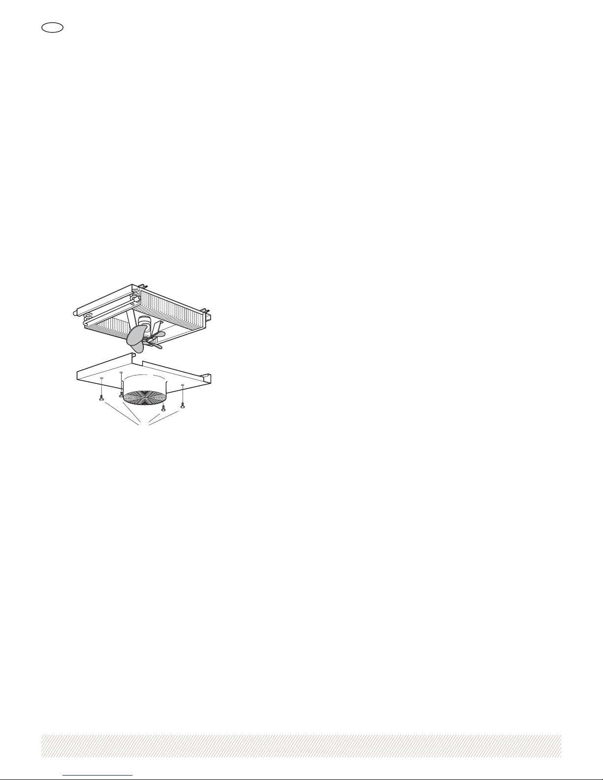
2. Irrota neljä ruuvia (A) ja irrota etuosa, ks. Kuva 5.
3. Irrota puhaltimen lukitusruuvi ja irrota puhallin moottorista.
4. Irrota sähköjohto kytkentärasiasta.
5. Irrota neljä ruuvia, jotka kiinnittävät moottorin sen kiinnikkeeseen, ja irrota moottori.
6. Uusi moottori asennetaan noudattamalla edellä
annettuja ohjeita päinvastaisessa järjestyksessä.
7. Tarkista, että puhaltimen pyörä on puhallinrenkaan
keskellä ja että puhaltimen pyörimissuunta on pyörimistä osoittavan nuolen mukainen.
8. Käynnistä ilmanlämmitin.
A
Kuva 5. Etuosan irrotus
Jäätymisvaara
Laitteistoissa, joiden ympäristölämpötila on alle 0 °C, on
olemassa jäätymisvaara ja sen seurauksena laitteiston rikkoutumisvaara, mikäli lämmönvaihdin pääsee jäähtymään
liikaa. Ellei laitetta aiota käyttää talvella, ilmanlämmittimestä tulee tyhjentää vesi. Tyhjennä jäljelle jäänyt vesi
paineilmalla, sillä ilmanlämmintä ei voi muuten tyhjentää
vedestä kokonaan. Ilmanlämmintä ei tarvitse tyhjentää,
jos siinä käytettyyn veteen on lisätty pakkasnestettä.
Pitkäaikainen säilytys
Kun ilmanlämmitintä aiotaan säilyttää pitkän aikaa, tulee
noudattaa seuraavia ohjeita:
• Säilytä ilmanlämmitintä sisätiloissa siinä asennossa,
johon se aiotaan asentaa.
• Peitä ilmanlämmitin lujitemuovilla tai muulla mekaanisella suojalla, jotta epäpuhtaudet ja vesi eivät pääsisi
lämmittimen sisään likaamaan ja vahingoittamaan
lamellirunkoa ja puhallinyksikköä.
• Ilmanlämmittimen putkiyhteissä tulee olla tulpat.
• Jos ilmanlämmitintä säilytetään kosteassa ympäristössä, sen pintakäsittely tulee tarkastaa säännöllisesti
vaurioiden estämiseksi. Mahdolliset vauriot tulee
korjata korjausmaalaamalla.
Kunnossapito ja huolto
Page 22
1034564 Oikeus muutoksiin pidätetään
Ilmanlämmitin LVD
FI
22
Tekniset tiedot
Ilman maksimilämpötila moottorin läheisyydessä: +70 ˚C
Ilman minimilämpötila moottorin läheisyydessä: -15 ˚C
Suurin sallittu käyttöpaine: 1,6 MPa lämpötilassa 100 ˚C
Kaikki lämmönvaihtimet on vuototestattu kuivalla ilmalla
vedenpinnan alla.
Moottoritiedot
Moottoria koskevat tiedot on merkitty kojekilpeen.
Mitat, paino ja tilavuus
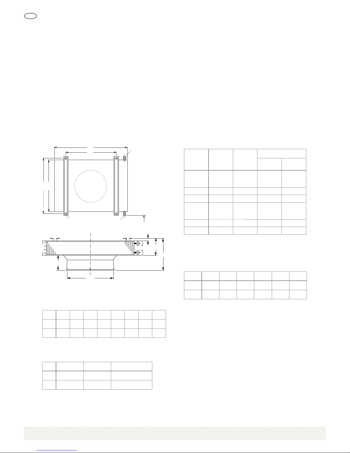
30
Ø 15
CB
A
D
K
K
20
E
F
H
Ø G
Kuva 6. Mitat
Taulukko 1. Mitat (mm)
LVDV ABCDEFGH
40 930 600 635 760 155 345 406 190
50 1130 700 735 960 220 380 514 160
Taulukko 2. Paino, tilavuus ja putkiyhteet
LVDV Paino (kg) Tilavuus (l) K (putkiyhde)
40 31 1,6 DN 20
50 45 3,8 DN 25
Lämmönvaihdin
Lämmönvaihtimen putket on mekaanisesti laajennettu
lamelleja vasten. Lamellit on valmistettu kokonaisista
urattomista levyistä pölyn ja kuitujen lamellirunkoon tarttumisen estämiseksi.
Puhallinyksikkö
Puhallinyksikön moottori on kuulalaakeroitu laippamoottori, joka on varustettu lämpösuojalla (ei 3-vaihe) ja automaattisella palautuksella. Puhaltimen pyörässä on napa
maalattua terästä ja siivet alumiinia.
Taulukko 3. Tekniset tiedot, puhallinyksikkö
LVDV
Kierros luku
(rpm)
Nim.teho
(kW)
Nimellisvirta (A), 50 Hz
1-vaihe
230 V
3-vaihe
400 V Y
40-1
1300
1)
900
670
0,15
1,50
1,0
0,7
–
–
–
40-6 920
1)
0,18 – 0,7
40-4 1380
1)
0,18 – 0,7
50-1
900
1)
670
570
0,17
1,7
1,2
0,7
–
–
–
50-6 920
1)
0,18 – 0,7
50-4 1410
1)
0,55 – 1,5
1)
Kierrosluku toimitettaessa. Muut kierrosluvut saadaan moottorin vaihto-
kytkennällä, ks. Kuvat 8-10.
Taulukko 4. Pyörimisnopeudet jännitteenohjauksen säätölaitteilla
LVDV 230 V 150 V 130 V 115 V 100 V 80 V
40-1 1300
1)
980
1)
820 690
1)
560 380
50-1 900
1)
770 690
1)
610
1)
510 370
1)
Kierrosluku toimitettaessa
Kotelointiluokat
Moottori: IP55
Kytkentärasia: IP44
Tekniset tiedot
Page 23
1034564 Oikeus muutoksiin pidätetään
Ilmanlämmitin LVD
FI
23
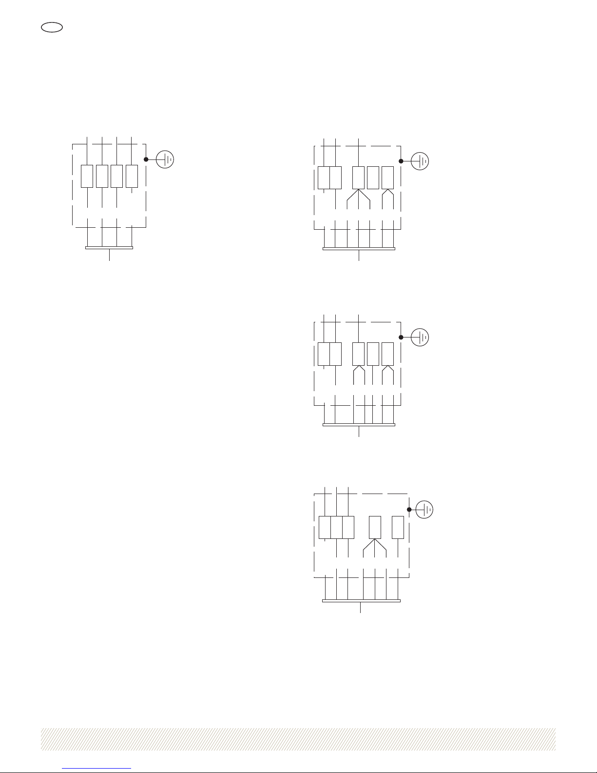
3-vaihe
R S T PE
12
3
Keltainen/
Vihreä
Moottori
Kuva 7. Y-kytkentä, tehdasasetus
1-vaihe, varustettu lämpösuojalla
PE L N
12345 6
keltainen/
vihreä
Moottori
Kuva 8. Suuri pyörimisnopeus, tehdasasetus
12
3456
PE L N
keltainen/
vihreä
Moottori
Kuva 9. Keskisuuri pyörimisnopeus
12 34 56
PE L N
keltainen/
vihreä
Moottori
Kuva 10. Alhainen pyörimisnopeus
Kytkentäkaavio
Page 24
Luvata Söderköping AB
SE-614 81 Söderköping, Sweden
Phone +46 121 191 00
Fax +46 121 101 01
www.luvata.com/coiltech
Ilmanlämmitin LVD
FI
5000-0096 • September 2009
COILTECHTUOTE VALMISTAJA LUVATA SÖDERKÖPING AB
Vakiomalli
Ilmanlämmitin LVDV-aa-b-c-d
Kojekoko (aa)
40, 50
Moottori (b)
1 = 1x230 V
4 = 3x400 V, 4-nap. (ei säätöä, c = 0)
6 = 3x400 V, 6-nap. (ei säätöä, c = 0)
Säätö (c)
0 = ei säätöä
A = vaihtoehto A
B = vaihtoehto B
C = vaihtoehto C
Rakennenumero (d)
1 = 2004 –
Ohjaus- ja säätölaitteet
Asennusvaihtoehdot LVDZ-a-1
Tyyppi (a)
A = vaihtoehto A
B = vaihtoehto B
C = vaihtoehto C
Lisävarusteet
Kattoripustimet, sarja LVDZ-03-1
Jatko-osa LVDZ-04-bb
Kojekoko (bb)
40, 50
Varaosat LVDV 40:lle
Puhaltimen pyörä LVDV-99-01-5
Moottori (1x230 V, 3 nopeutta) LVDV-99-02-12
Moottori (3x400 V, 4-napainen) LVDV-99-02-14
Moottori (3x400 V, 6-napainen) LVDV-99-02-16
Kosketussuojat LVDV-99-03-3
Lämmönvaihdin LVDV-99-04-1
Varaosat LVDV 50:lle
Puhaltimen pyörä LVDV-99-01-6
Moottori (1x230 V, 3 nopeutta) LVDV-99-02-13
Moottori (3x400 V, 4-napainen) LVDV-99-02-17
Moottori (3x400 V, 6-napainen) LVDV-99-02-15
Kosketussuojat LVDV-99-03-4
Lämmönvaihdin LVDV-99-04-2
Tuotekoodi
 Loading...