


Dosing
Conveying
Control
Liquids
Gases
Systems
Original operating instructions
© Lutz-Jesco GmbH 2018
BA-40900-02-V01
Gas warning device
EASYCON GW
Operating instructions
Read the operating manual!
The user is responsible for installation and operation related mistakes!


Table of Contents
3
© Lutz-Jesco GmbH 2018
Subject to technical changes.
180426
BA-40900-02-V01
Gas warning device EASYCON GW Operating instructions
Table of Contents
1 Notes for the Reader ..........................................................4
1.1 General non-discrimination ...................................................... 4
1.2 Explanation of the signal words ................................................ 4
1.3 Explanation of the warning signs .............................................. 4
1.4 Identification of warnings ......................................................... 4
1.5 Identification of action instructions ........................................... 4
2 Safety ................................................................................. 5
2.1 General warnings .....................................................................5
2.2 Hazards due to non-compliance with the safety instructions .....5
2.3 Working in a safety-conscious manner .....................................5
2.4 Personnel qualification .............................................................5
3 Intended use ......................................................................7
3.1 Notes on product warranty .......................................................7
3.2 Intended purpose .....................................................................7
3.3 Foreseeable misuse .................................................................7
4 Product description ...........................................................8
4.1 Scope of delivery .....................................................................8
4.2 Design and function .................................................................8
4.3 Rating plate ............................................................................. 9
5 Technical data .................................................................. 10
5.1 EASYCON GW.........................................................................10
5.2 Sensors .................................................................................10
6 Dimensions ......................................................................11
6.1 Outside dimensions ...............................................................11
6.2 Drillhole dimensions ..............................................................11
7 Installation ....................................................................... 12
7.1 Principles ..............................................................................12
7.2 Installation on the wall ...........................................................12
7.3 Electrical installation ..............................................................12
7.4 Terminal connection ...............................................................13
7.5 Connecting the sensor ...........................................................14
7.6 Connecting the signal technology ...........................................15
7.7 Digital inputs .........................................................................16
7.8 RC protection for relay ............................................................16
7.9 Connecting Ethernet ..............................................................17
8 Commissioning ................................................................ 18
8.1 First steps ..............................................................................18
8.2 Configuration .........................................................................18
8.3 Password protection ..............................................................20
8.4 Network settings ....................................................................20
9 Operation ..........................................................................21
9.1 Confirming a message ...........................................................21
9.2 Viewing the trend display .......................................................21
9.3 Access via network ................................................................21
10 Maintenance ....................................................................22
10.1 Maintenance intervals ..........................................................22
10.2 Renewing the sensor ...........................................................22
10.3 Keeping logfiles ...................................................................22
10.4 Updating software................................................................22
10.5 Replacing the fuse ...............................................................23
10.6 Resetting the settings ..........................................................23
10.7 Finishing maintenance .........................................................23
11 Troubleshooting ............................................................... 24
12 Modbus addresses ........................................................... 25
13 EU Declaration of Conformity ........................................... 28
14 Warranty claim .................................................................29
15 Index .................................................................................30

Notes for the Reader
Identification of action instructions
4
© Lutz-Jesco GmbH 2018
BA-40900-02-V01
Gas warning device EASYCON GW Operating instructions
1 Notes for the Reader
This operating manual contains information and behaviour rules for the
safe and designated operation of the device.
Observe the following principles:
nRead the entire operating manual prior to starting-up the device.
nEnsure that everyone who works with or on the device has read the
operating manual and follows it.
nMaintain the operating manual throughout the service life of the
device.
nPass the operating manual on to any subsequent owner of the device.
1.1 General non-discrimination
In this operating manual, only the male gender is used where grammar
allows gender allocation. The purpose of this is to make the text easy to
read. Men and women are always referred to equally. We would like to
ask female readers for understanding of this text simplification.
1.2 Explanation of the signal words
Different signal words in combination with warning signs are used in this
operating manual. Signal words illustrate the gravity of possible injuries if
the risk is ignored:
Signal word Meaning
DANGER
Refers to imminent danger. Ignoring this sign may
lead to death or the most serious injuries.
WARNING
Refers to a potentially hazardous situation.
Failure to follow this instruction may lead to death
or severe injuries.
CAUTION
Refers to a potentially hazardous situation.
Failure to follow this instruction may lead to
minor injury or damage to property.
NOTE
Refers to a danger which, if ignored, may lead to
risk to the machine and its function.
Table 1: Explanation of the signal words
1.3 Explanation of the warning signs
Warning signs represent the type and source of a danger:
Warning sign Type of danger
General danger
Danger from electrical voltage
Danger from poisonous substances
Danger of damage to machine or functional
influences
Table 2: Explanation of the warning signs
1.4 Identification of warnings
Warnings are intended to help you recognise risks and avoid negative
consequences.
This is how warnings are identified:
Warning sign
SIGNAL WORD
Description of danger.
Consequences if ignored.
ðThe arrow signals a safety precaution to be taken to eliminate the
danger.
1.5 Identification of action instructions
This is how pre-conditions for action are identified:
ü
Pre-condition for action which must be met before taking action.
@A resource such as a tool or auxiliary materials required to perform
the operating instructions.
This is how instructions for action are identified:
èSeparate step with no follow-up action.
1. First step in a series of steps.
2. Second step in a series of steps.
4Result of the above action.
ü
Action completed, aim achieved.

Safety
Personnel qualification
5
© Lutz-Jesco GmbH 2018
Subject to technical changes.
180426
BA-40900-02-V01
Gas warning device EASYCON GW Operating instructions
2 Safety
2.1 General warnings
The following warnings are intended to help you eliminate the dangers
that can arise while handling the device. Risk prevention measures always apply regardless of any specific action.
Safety instructions warning against risks arising from specific activities
or situations can be found in the respective sub-chapters.
DANGER
Mortal danger from electric shock!
Wrongly connected or located cables or damaged ones can injure you.
ðReplace damaged cables without delay.
ðDo not use extension cables.
ðDo not bury cables.
ðSecure cables to avoid being damaged by other equipment.
CAUTION
Increased risk of accidents due to insufficient qualification of personnel!
The device may only be installed, operated and maintained by personnel with sufficient qualifications. Insufficient qualification will increase
the risk of accidents.
ðEnsure that all action is taken only by personnel with sufficient and
corresponding qualifications.
ðPrevent access to the system for unauthorised persons.
NOTE
Do not dispose of the device in the domestic waste!
Do not dispose of electric devices via the domestic waste.
ðThe device and its packaging must be disposed of in accordance
with locally-valid laws and regulations.
ðDispose of different materials separately and ensure that they are
recycled.
2.2 Hazards due to non-compliance with the safety
instructions
Failure to follow the safety instructions may endanger not only persons,
but also the environment and the device.
The specific consequences can be:
nFailure of major unit and system functions,
nfailure of required maintenance and repair methods,
ndanger for individuals through dangerous dosing media,
ndanger to the environment caused by chlorine leaking from the
system.
2.3 Working in a safety-conscious manner
Besides the safety instructions specified in this operating manual, further
safety rules apply and must be followed:
naccident prevention regulations
nsafety and operating provisions,
nsafety regulations on handling hazardous substances,
nenvironmental protection provisions,
napplicable standards and legislation.
2.4 Personnel qualification
Any personnel who work on the device must have appropriate special
knowledge and skills.
Anybody who works on the device must meet the conditions below:
nattendance at all the training courses offered by the owner,
npersonal suitability for the respective activity,
nsufficient qualification for the respective activity,
ntraining in how to handle the device,
nknowledge of safety equipment and the way this equipment functions,
nknowledge of this operating manual, particularly of safety instructions
and sections relevant for the activity,
nknowledge of fundamental regulations regarding health and safety
and accident prevention.
All persons must generally have the following minimum qualification:
ntraining as specialists to carry out work on the device unsupervised,
nsufficient training that they can work on the device under the
supervision and guidance of a trained specialist.
These operating instructions differentiate between these user groups:
2.4.1 Specialist staff
Thanks to their professional training, knowledge, experience and knowledge of the relevant specifications, specialist staff are able to perform the
job allocated to them and recognise and/or eliminate any possible dangers by themselves.
2.4.2 Trained electricians
Due to their professional training, knowledge and experience as well as
knowledge of specific standards and provisions, trained electricians are
able to do the electrical work assigned to them and to recognise and
avoid any potential dangers by themselves.

Safety
Personnel qualification
6
© Lutz-Jesco GmbH 2018
BA-40900-02-V01
Gas warning device EASYCON GW Operating instructions
They are specially trained for their specific working environment and are
familiar with relevant standards and provisions.
They must comply with the legally binding regulations on accident prevention.
2.4.3 Trained persons
Trained persons have received training from the operator about the tasks
they are to perform and about the dangers stemming from improper behaviour.
Trained persons have attended all trainings offered by the operator.
2.4.4 Personnel tasks
In the table below you can check what qualifications are the pre-condition for the respective tasks. Only people with appropriate qualifications
are allowed to perform these tasks!
Qualification Activities
Specialist staff nTransportation
nMechanical installation
nCommissioning
nTaking out of operation
nFault rectification
nMaintenance
nRepairs
nDisposal
Trained electricians nElectrical installation
Trained persons nControl
Table 3: Personnel qualification

Intended use
Foreseeable misuse
7
© Lutz-Jesco GmbH 2018
Subject to technical changes.
180426
BA-40900-02-V01
Gas warning device EASYCON GW Operating instructions
3 Intended use
3.1 Notes on product warranty
Any non-designated use of the device can impair its function and the protection provided. This leads to invalidation of any warranty claims!
Please note that liability is on the side of the user in the following cases:
nThe device is operated in a manner which is not consistent with these
operating instructions, particularly safety instructions, handling
instructions and the section "Intended Use".
nInformation on usage and environment (see section 5 “Technical
data” on page10) is not adhered to.
nIf people operate the device who are not adequately qualified to carry
out their respective activities.
nUnauthorised changes are made to the device.
3.2 Intended purpose
As a safety device, the gas warning device detects dangerous gases in
the surrounding air. Should limit values be exceeded, the device will notify
the signal technology such as signal lamps or signal bugles, which will
notify a danger.
3.3 Foreseeable misuse
The following section provides information regarding the device applications which are classified as non-intended use. This section is intended to
allow you to detect possible misuse in advance and to avoid it.
Foreseeable misuse is assigned to the individual stages of the product
lifetime:
3.3.1 Incorrect assembly
nConnecting the mains voltage without a protective earth.
nNon-fused or non-standard mains voltage.
nNot possible to immediately or easily disconnect the power supply.
nWrong connecting cables for mains voltage.
nAcoustic and optical signal generators connected to the incorrect.
clamps or incorrectly configured.
nProtective earth removed.
3.3.2 Incorrect start-up
nCommissioning with damaged or obsolete sensors.
nCommissioning without the establishment of all protective measures,
fastenings etc.
3.3.3 Incorrect operation
nProtective equipment not functioning correctly or dismantled.
nUnauthorised modification of the gas warning unit.
nIgnoring of alarm or error messages.
nThe elimination of alarm or error messages by insufficiently-qualified
personnel.
nBridging the external fuse.
nDifficult operation due to insufficient lighting or poor access to the
device.
nOperation not possible due to dirty or illegible display.
3.3.4 Incorrect maintenance
nCarrying out maintenance during ongoing operation.
nNo adequate or regular inspection of correct functioning.
nNo replacement of damaged parts or cables.
nNo securing against reactivation during maintenance work.
nUse of the wrong spare parts.

Product description
Design and function
8
© Lutz-Jesco GmbH 2018
BA-40900-02-V01
Gas warning device EASYCON GW Operating instructions
4 Product description
4.1 Scope of delivery
Please compare the delivery note with the scope of delivery. The following items are part of the scope of delivery:
nGas warning device
nUp to 4 sensors
nOperating instructions
4.2 Design and function
4.2.1 Installation example
Fig. 1: Simple example installation of a chlorine gas room
Position Description Position Description
1 EASYCON GW gas warning device 7 Chlorine tank
2 Signal lamp 8 Safety blow-off valve
3 Alarm horn 9 ChlorStop valve
4 Gas sensor 10 Activated carbon cartridge
5 Safety shutoff valve 11 Heater
6 Changeover switch
Table 4: Simple example installation of a chlorine gas room
11
1
4
7
10
8
6
5
2
3
9

Product description
Rating plate
9
© Lutz-Jesco GmbH 2018
Subject to technical changes.
180426
BA-40900-02-V01
Gas warning device EASYCON GW Operating instructions
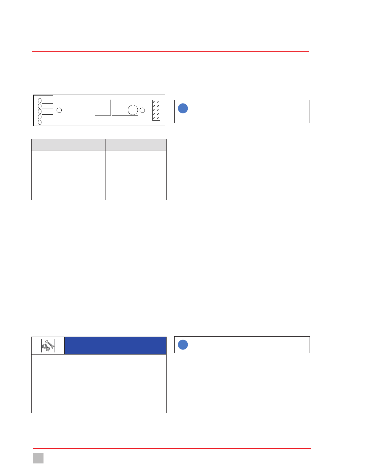
4.2.2 Main view
The main menu view will appear upon the start of the device or 5 minutes
after the last input. The main view shows the current values from up to
four sensors and further information.
Fig. 2: Main view with two sensors
No. Function
1 Login / password settings
2 Date / time
3 Values / limit values
4 Main menu
5 File Browser
6 Status row for messages
Table 5: Components
4.2.3 Functions of the device
The stationary device monitors the surrounding air using sensors which
can detect various gases such as chlorine-gas, chlorine dioxide or ozone.
They can also measure the room temperature.
If the sensors notify too high a value, the device will issue an alarm and
the connected safety devices such as a signal bugle or sprinkler installation can activate.
4.3 Rating plate
There is information on the equipment about safety or the product's way
of functioning. The information must stay legible for the duration of the
service life of the product.
100 - 240 V AC, 50/60 Hz, IP 65
XX/XXXX
S/N: XXXXXXXXXX
P/N:
Made in
Germany
*102A12345678*
*12345678012345*
Gaswarngerät EASYCON GW
Lutz-Jesco GmbH 30900 Wedemark
Am Bostelberge 19 Germany
Fig. 3: Rating plate EASYCON GW
No. Description
1 Product name
2 Electrical specifications / protection class
3 Label showing conformity with applicable European directives
4 WEEE label
5 Serial number
6 Part number
7 Month / year of manufacture
Table 6: Rating plate
6
2
1
4 5
3
7
6
5
2
1
3 4

Technical data
10
© Lutz-Jesco GmbH 2018
BA-40900-02-V01
Gas warning device EASYCON GW Operating instructions
5 Technical data
5.1 EASYCON GW
Information Value
Voltage supply 100 - 240 V AC, 50 / 60 Hz
Power consumption max. 20 W
Housing dimensions 302 x 240 x 107 mm
Temperature sensor -10 ... +100 °C
Load capacity of the relay 230 V AC, 5 A (ohmic resistive load)
Load capacity of the optocoupler 80 V DC, 5 mA
Load capacity of the bugle relay 250 V AC, 10 A (ohmic resistive load)
Analogue outputs 0/4 - 20 mA, max. load 500 ohms
Interfaces Ethernet Modbus TCP/IP
Protection class IP 65
Ambient temperature -5 ... +45 °C
Air humidity max. 95 %, non condensing
Table 7: Technical data
5.2 Sensors
Information Value
Measuring gas Chlorine (Cl2) Chlorine dioxide (ClO2) Ozone (O3)
Measuring range 0 - 10 ppm 0 - 1 ppm 0 - 1 ppm
Reaction time approx. 30 s
Dimensions 135 x Ø 33 mm
Housing material PVC
Protection class IP 54
Weight approx. 0.2 kg
Ambient temperature -10 ... +40 °C
Air humidity max. 90 %, non condensing
Service life max. 2 years, depending on the operating conditions
Table 8: Technical data

Dimensions
11
© Lutz-Jesco GmbH 2018
Subject to technical changes.
180426
BA-40900-02-V01
Gas warning device EASYCON GW Operating instructions
6 Dimensions
All dimensions in millimetres (mm).
6.1 Outside dimensions
Fig. 4: Outside dimensions
6.2 Drillhole dimensions
Fig. 5: Dimensions for wall mounting
302
240
267
171

Installation
Electrical installation
12
© Lutz-Jesco GmbH 2018
BA-40900-02-V01
Gas warning device EASYCON GW Operating instructions
7 Installation
DANGER
Mortal danger from electric shock!
Improperly installed or damaged components in the electronics installation can cause injury.
ðEnsure that all work on the electrical installation is performed by a
qualified electrician.
ðEnsure that all work on the electrical installation is performed in a
de-energised state.
ðEnsure that the power supply is secured with a fault current
protective circuit.
ðReplace damaged cables or components without delay.
7.1 Principles
Make sure that the installation location complies with the following requirements:
nThe display is easily accessible and is visible.
nPlan to leave min. 20 cm free space for the installation of the cable
underneath the device. You must be able to install the cable without
kinking or damage.
nMount the sensors 30 cm above the ground.
nCompliance with the permissible ambient temperatures (see section 5
“Technical data” on page10).
7.2 Installation on the wall
Resources required:
@Assembly kit
@Drill
@Slotted screwdriver
Perform the following steps:
1. Drill the four drillholes for wall mounting. The exact dimensions are
stated in section 6 “Dimensions” on page11.
2. Unscrew the screw on the right-hand side of the device and pull out
the rod.
4You can now open the device.
3. Open the device and use the screws for wall mounting. Ensure that
the device is secured to the wall.
4. Close the device again using the rod.
ü
The device is fitted on the wall.
7.3 Electrical installation
The voltage supply to your device can now be performed via a normal
Schuko plug or a control cabinet. Perform the specifications of this section for devices without a pre-fitted Schuko plug.
Precondition for action:
ü
The device was installed in accordance with section 7.2 Installation
on the wall.
ü
A voltage supply with 100 - 240 V AC (50 / 60 Hz) is available.
ü
The voltage supply is deactivated before the start and secured
against reactivation.
ü
The housing is open.
Resources required:
@Schuko plug
@Wire end sleeves 0.75 - 2.5 mm²
1. Fit wire end sleeve to the cable ends if the supply cable does not
have them.
2. Open the device housing.
3. Lead the supply cable through a cable screw connection to the un-
derside of the device.
4. Turn the cable screw connection union nut until the line is fixed in the
screw connection so that the screw connection performs strain relief.
Ensure that the feed cable is installed loosely.
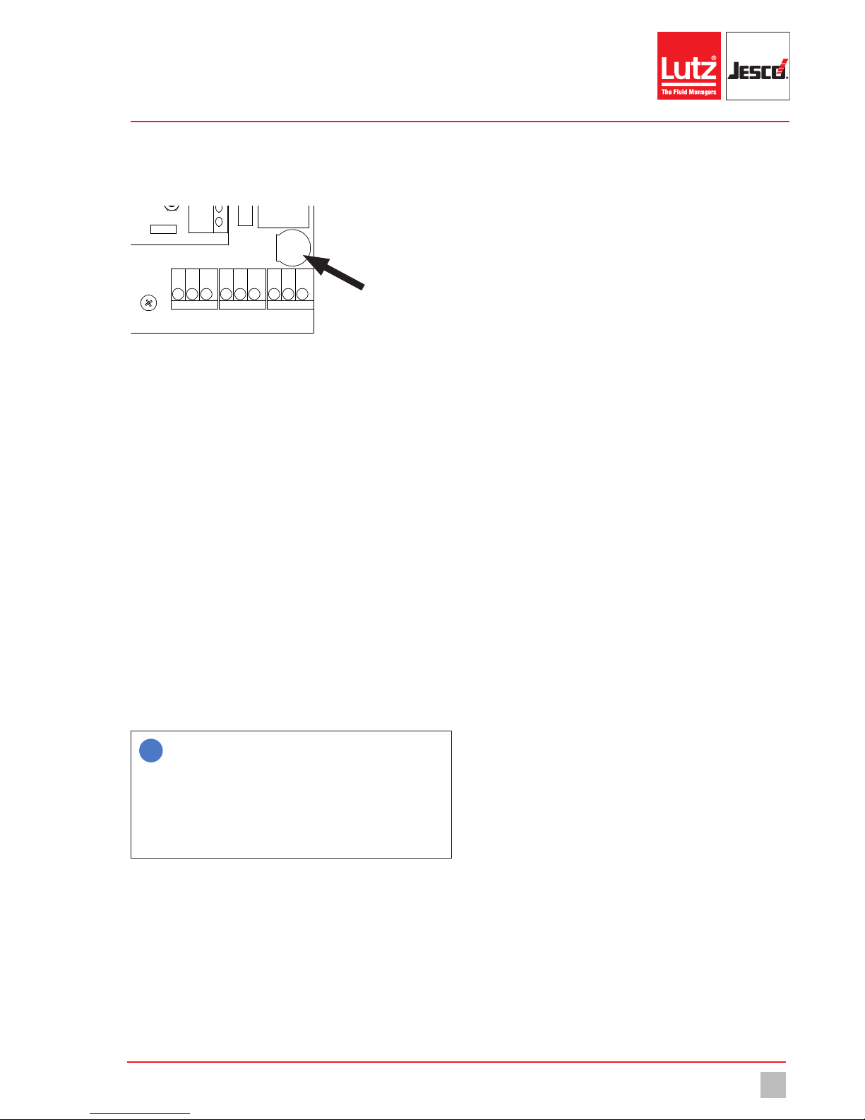
5. Connect the voltage supply to the clamps 44 - 52. Observe the division into protective earth (PE), neutral conductor (N) and the phase (L)
on the circuit board.
Fig. 6: Connected voltage supply
ü
Electrically installation
i
Only 3 of 9 clamps are required for connection of the voltage
supply. You can use the free clamps to supply further devices
with voltage.
The contact load rating amounts to max. 4 A.

Installation
Terminal connection
13
© Lutz-Jesco GmbH 2018
Subject to technical changes.
180426
BA-40900-02-V01
Gas warning device EASYCON GW Operating instructions
7.4 Terminal connection
8192 3 4 5 6 7 10
111213141516171819 20
29303132333435 3621222324252627 2837383940
41 42
43
44
45
46
47
48
49 50 51
52
USB
Fig. 7: Overview of the connection clamps.
Terminal Function Description
1 - 12 Not wired
13
Analogue output 1
+
0/4 - 20 mA, max. working resistance 500 Ω
14 -
15
Analogue output 2
+
16 -
17
Analogue output 3
+
18 -
19
Analogue output 4
+
20 -
21 - 36 Digital inputs 1 - 8 Freely-configurable
37 - 40 Ethernet connection
41 - 43 Horn relay
Clamps 41+42 normal off
Clamps 42+43 normal on
44 - 46
Connection supply voltage
Protective earth (PE)
47 - 49 Neutral line (N)
50 - 52 Phase (L)
Table 9: Terminal connection
i
When performing the clamp connection of the input circuit board and the connection of the sensors, comply with the specifications of section7.5 on page 14.
When performing the clamp connection of the output circuit board and the connection of the signal technology, comply with the specifications of section 7.6 on page 15.
Input 1
Input 2
Input 3
Input 4
Output 1
Output 2
Output 3
Output 4
Ethernet
Digital inputs
0/4 - 20 mA
Horn relay
Voltage
Installation
Connecting the sensor
14
© Lutz-Jesco GmbH 2018
BA-40900-02-V01
Gas warning device EASYCON GW Operating instructions
7.5 Connecting the sensor
You can connect up to four sensors to the gas warning system. You can
also connect a PT 100 temperature sensor to every input circuit board to
monitor the room temperature.
4
3
2
1
5
Fig. 8: Input circuit board
Terminal Function Description
1 Temperature input
PT100
2 Temperature input
3 Measuring electrode GN (green)
4 Counter electrode WH (white)
5 Reference electrode BN (brown)
Table 10: Clamp connection of the input circuit board
Precondition for action:
ü
The voltage supply has been disconnected and protected against
re-connection.
ü
The housing is open.
Resources required:
@Sensors
@Suction connection
@Pipe clip
@Wire end sleeves 0.25 mm²
Perform the following steps:
1. Screw the pipe clip to the wall 30 cm above the floor.
2. Fix the sensor in the pipe clip. The sensor opening must point down-
wards.
3. Connect the connecting cable to the wall and lead it to the device.
NOTE
Electronic distortion of the measurement results.
Incorrect installation of the electrical cables can distort the measurement results. As a result, the control of connected devices can be faulty.
ðDo not route the connecting cable parallel to the mains and control
connections, and always with a clearance of at least 15cm. Lay
connection junctions at an angle of 90°.
ðUse a max. 50 m signal cable.
4. Shorten the connecting cable to the required length. Apply a wire end
sleeve to the end of every wire.
5. Open the device housing and lead the cable into the inside of the
housing through one of the cable screw connections on the underside of the housing.
6. Connect the three coloured wires onto the input circuit board clamp
block. Comply with Table 10 “Clamp connection of the input circuit
board” on page14.
i
This is a standard cable, the shield of which can function as a
fourth wire. The cable shield, however, is not connected.
Shorten the shield to the cable insulation or pinch it off.
ü
Sensor connection completed.
Testing the sensor functionality
You can check the electrical connection and the functionality of the connected sensors.
Precondition for action:
ü
The installation has been completed in accordance with section 7
“Installation” on page12.
ü
The device is activated.
Perform the following steps:
1. In the main menu under System > Inputs, navigate to the “Sensors”
tab.
2. Select “Sensor 1” and press the “Test” button. “Sensor test” will be
displayed for a short time.
4The device checks whether the selected sensor has been connected
correctly.
3. Repeat step 2 for all sensors. If the sensor test has not been successful, the “Sensor error” alarm will be displayed. In this case, check the
sensor connecting cable and whether the sensor has been inserted
in the sensor bracket completely.
4. Test the functionality of the sensors and actors (e.g. signal lamps and
signal bugles) with test gas. Comply with the specifications of the
test gas operating instructions. The display must show an increase of
the gas concentration. Given correspondingly set limit values, it must
also trigger actors (such as the signal bugle).
ü
Functionality tested.
i
Always inform the connected stations and departments before
triggering a test alarm.

Installation
Connecting the signal technology
15
© Lutz-Jesco GmbH 2018
Subject to technical changes.
180426
BA-40900-02-V01
Gas warning device EASYCON GW Operating instructions
7.6 Connecting the signal technology
Depending on the equipment of the device, you have up to three different
methods with which to connect signal technology to the gas warning device and to control and supply it with current.
This section describes the bugle relay, the relay output circuit board and
the optocoupler output circuit board.
Precondition for action:
ü
The housing is open.
ü
The voltage supply has been disconnected and protected against
re-connection.
Resources required:
@Signal technology
7.6.1 Horn relay
You can connect an individual signal bugle to the bugle relay
(clamps41-43) and control it. If a signal bugle is connected to the bugle
relay, the alarm message must be confirmed directly on the device. The
bugle relay is especially suited for an alarm at the first limit value.
41 42
43
Fig. 9: Horn relay
Terminal Function Description
41 + 42 normal off
The relay works on these
clamps as a closer.
42 + 43 normal on
The relay works on these
clamps as an opener.
Table 11: Bugle relay clamp connection
Perform the following steps:
1. Fit the signal bugle.
2. Lead the connecting cable through a cable screw connection to the
underside of the device.
3. Connect the signal technology used either to clamps 41 and 42 (normal off) or 42 and 43 (normal on).
4Note: You can adjust the action of the bugle relay in the output set-
tings. Further information is available in section 8.2.2.1 “Bugle” on
page19.
ü
Connection of the signal bugle complete.
7.6.2 Output circuit board (relay)
You can control the signal technology (e.g. bugles or signal lamps) with
the relay output circuit boards. To this end, the device can be fitted with
up to four relay output circuit boards, which can be used for a pre-alarm
and a master alarm respectively.
Application example: You can evaluate sensors in two different rooms using two relay output circuit boards.
Section 8.1 “First steps” on page 18 informs you how to set the limit
values individually.
79831_1
Bild BA CM Ausgangsmodul 2 Relais
4
3
2
1
Fig. 10: Output circuit board (relay)
Terminal Function Description
1
Relay X.2
Main alarm
(Limit value 2)
2
3
Relay X.1
Pre-alarm
(Limit value 1)
4
Table 12: Clamp connection of the output circuit board (relay)
Perform the following steps:
1. Fit the signal technology.
2. Lead the connecting cable through one of the cable screw connec-
tions to the underside of the device.
3. Connect the signal device for the master alarm to the clamps 1+2.
4. Connect the signal device for the pre-alarm to the clamps 3+4.
ü
Connection of the relay output circuit board completed.
i
Only the limit values 1 and 2 can be outputted from outputs1and2.
Only outputs 3 and 4 are freely-configurable and can output
further signals.

Installation
RC protection for relay
16
© Lutz-Jesco GmbH 2018
BA-40900-02-V01
Gas warning device EASYCON GW Operating instructions
7.6.3 Output circuit board (optocoupler)
The output circuit boards can optionally be fitted with optocouplers. Optocoupler circuit boards serve the output of a digital signal , e.g. to a PLC or
a superordinate control centre. The outputs can be freely-configurable
and can relay alarms, the exceedance of limit values, sensor errors or the
switching of digital inputs.
79832_1
4
3
2
1
Fig. 11: Output circuit board (optocoupler)
Terminal Function Description
1 +
Opto X.2
Freely-configurable
(only at output 3 and 4)
2 -
3 +
Opto X.1
Freely-configurable
(only at output 3 and 4)
4 -
Table 13: Clamp connection output circuit board (optocoupler)
Testing the signal technology
The device enables you to test the correct connection of the signal technology. The test simulates an alarm and the connected signal technology
is activated.
Take the alarm chain into account before conducting the test and inform
any connection points or interrupt the alarm chain for the period of the
test.
Precondition for action:
ü
The signal technology was installed in accordance with section 7.6
“Connecting the signal technology” on page15.
ü
The device housing cover is closed.
ü
The voltage supply has been established and the device has been
switched on.
Instruction:
1. In the main menu, navigate to System > Outputs > Test.
4You will now see all the outputs.
2. Select the outputs that you would like to test.
3. Press "Start”.
4The signal technology connected will now be activated as in the
case of an alarm.
ü
Signal technology tested.
7.7 Digital inputs
You can use up to 8 digital inputs to evaluate switching statuses and to
detect them as alarm message which are to be documented in the logfiles.
Further information about the settings of the digital inputs can be found in
section 8.2.1.3 “Digital” on page18.
7.8 RC protection for relay
When connecting to the relay, note that inductive loads must be suppressed. If this is not possible, the relay contact on the device terminal
must be protected by an RC protective circuit / interference suppression
element.
If devices with inductive loads from a nominal current of 1 A are connected to a relay, the contacts in the relay may become bonded. Thus, the device will operate in an uncontrolled manner. To prevent bonding if the load
circuit suffers a short-circuit, the relays must be protected separately on
the maximum relay switching current.
Precondition for action:
ü
You would like to connect an inductive load to the relay.
Instruction:
1. Switch off the device.
2. Clamp the interference suppression element parallel to the inductive
load.
3. Should it prove impossible to perform point 2, clamp the interference
suppression element parallel to the relay output.
ü
RC element clamped.

Installation
Connecting Ethernet
17
© Lutz-Jesco GmbH 2018
Subject to technical changes.
180426
BA-40900-02-V01
Gas warning device EASYCON GW Operating instructions
7.9 Connecting Ethernet
You can use the Ethernet connection for the following actions:
nReading/writing via Modbus TCP/IP protocol (PLC or Computer)
nAccess via web browser
nAccess via TFTP server
The device has a network input in the form of a M12x1 socket. Lutz-Jesco GmbH offers different lengths of special twisted-pair network cables
to make the typical Ethernet RJ-45 plug connection. If you use third-party
cables, choose a Category 3 cable with an impedance of 100 Ohm or
above.
Pin Assignments Wire colours
1 TX- yellow
2 TX+
orange
3 RX- white
4 RX+ blue
- Screen -
Table 14: Ethernet connection socket
Fig. 12: Ethernet socket
Installing a wired network
During installation, comply with the following points:
nThe Ethernet is cabled in a star topology. The maximum cable length
is 100 m.
nYou must route separately as a bundle the different categories of
cables (e.g. power supply, data lines and sensitive lines for measuring
purposes). In this connection, cables should cross at an angle of 90°.
nThere must either be a minimum distance between the power cable
and data lines of 10 cm or you must install a partition or route the data
line in a metal pipe.
nOnly use screened cables and plug-in connectors.
nRoute copper wires outside cable support systems through plastic
pipes.
nTemperatures that are too high or too low result in lower mechanical
and electrical loading or lead to damage.
nData lines must only be subjected to a defined tensile load; otherwise,
the electrical or attenuation values can no longer be guaranteed.
nWhen pulling cables out of the cable drum, avoid looping or pulling
over sharp edges.
nWith copper wires, implement potential equalization; when doing this,
differentiate between hazardous and non-hazardous areas.
nElectrical, magnetic and electromagnetic fields affect signal
transmission and under some circumstances can destroy electronic
components.

Commissioning
Configuration
18
© Lutz-Jesco GmbH 2018
BA-40900-02-V01
Gas warning device EASYCON GW Operating instructions
8 Commissioning
8.1 First steps
You need to make a number of basic settings before operating the device.
This section leads you through initial commissioning.
Precondition for action:
ü
The device has been installed in accordance with section 7
“Installation” on page12.
ü
All system parts are ready for operation.
Configuration assistant
With initial commissioning, a configuration wizard will lead you through
the basic settings: your preferred language; sensors connected; signal
bugle; and two limit values.
Perform the following steps:
1. Set the preferred language and press on the arrow.
2. Set up the connected sensors and press the right-hand arrow. Fur-
ther information is available in section8.2.1.1.
3. Set up the bugle and press the right-hand arrow. Further information
is available in section 8.2.2.1 “Bugle” on page19.
4. Set up the limit values and press the right-hand arrow.
5. Press “Yes” in the dialogue field to save the settings.
ü
The configuration assistant has been ended.
i
You can start the configuration wizard manually by navigating
Menu item > System > Settings > Configuration and pressing
on “Edit”.
8.2 Configuration
The device is set up variably and can be individually adapted to meet your
requirements. As such, it is necessary to adjust the configuration of the
inputs and outputs to the sensors and signal technology used before
commissioning.
The following section leads you through the device configuration.
8.2.1 Input side
You can connect up to four sensors for various gases and the temperature. You can also use eight digital inputs.
8.2.1.1 Sensors
The sensors must be configured individually in the device to enable precise and error-free measurement of the gases. You can perform various
settings.
Perform the following steps:
1. In the main menu, navigate from System > Inputs to the “Sensors”
tab.
2. In the “Sensors” tab, configure every connected sensor and state the
following information.
3. Measured value: Choose from “Chlorine-gas”; “Chlorine dioxide”;
“Ozone” or “other”.
4. Unit: Choose between “ppm” (parts per million) or “Vol.-%” (volume
per cent).
5. Measuring range: Enter the maximum measuring range of the sensor.
6. Limit values: Enter the limit values for the pre-alarm and the master
alarm.
7. Room name: Give the sensor an individual name.
8. Slope: State the individual slope of the sensor.
ü
Configuration of the sensors completed.
8.2.1.2 Temperature
You can connect up to four temperature sensors to the device. This enables you to measure the temperatures at various positions.
Perform the following steps:
1. In the main menu under System > Inputs, navigate to the “Temperature” tab.
2. In the “Temperature” tab, configure every connected temperature
sensor and state the following information.
3. Measuring: Chose between “On” and “Off”.
4. Min-alarm: Activate or deactivate the “Min-alarm” and enter a tem-
perature under which the alarm will be triggered.
5. Max-alarm: Activate or deactivate the “Max-alarm” and enter a temperature above which the alarm will be triggered.
ü
Configuration of the temperature sensors completed.
8.2.1.3 Digital
You can use up to 8 digital inputs to evaluate switching statuses and to
detect them as alarm message which are to be documented in the logfiles.
Perform the following steps:
1. In the main menu under System > Inputs, navigate to the “Digital”
tab.
2. In the “Digital” tab, configure the inputs and state the following information.
3. Type: Select an individual name.

Commissioning
Configuration
19
© Lutz-Jesco GmbH 2018
Subject to technical changes.
180426
BA-40900-02-V01
Gas warning device EASYCON GW Operating instructions
4. Action: Choose between “OK = open” (N.O., working contact) or “OK
= contact” (N.C., break contact).
ü
Configuration of the digital inputs completed.
8.2.2 Output side
Depending on the equipment, you can connect the device to a range of
actors in the alarm chain. The following connection methods are available.
8.2.2.1 Bugle
The basic configuration of the device includes a bugle relay to which a
signal bugle or siren can be connected.
Perform the following steps:
1. In the main menu under System > Outputs, navigate to the “Bugle”
tab.
2. In the “Bugle” tab, configure the output and state the following information.
3. Action: Choose between “normal opened” (N.O., make contact) or
“normal closed” (N.C., break contact).
4. Latching: On = The alarm is active, until it is manually confirmed. OFF
= The alarm is deactivated automatically as soon as the limit value
has been undercut.
5. Relay triggers with: Chose whether this alarm should trigger at limit
value 1 or limit value 2. You can determine the limit values for every
sensor. See section 8.2.1.1 “Sensors” on page18.
6. Alarm delay: Determine how many seconds after the exceeding of
the limit value the alarm should be activated.
ü
Configuration of the bugle completed.
8.2.2.2 Limit values
You can set the action of the connected signal technology individually.
The limit values set here apply to sensor1/output 1 and sensor2/output2.
Perform the following steps:
1. In the main menu under System > Outputs, navigate to the “Limit
values” tab.
2. Working in the “Limit value” tab, configure the action of the various
output circuit boards and the connected signal technology.
3. Action: Choose between “normal opened” (N.O., make contact) or
“normal closed” (N.C., break contact).
4. Latching: On = The alarm is active, until it is manually confirmed. OFF
= The alarm is deactivated automatically as soon as the limit value
has been undercut.
5. Alarm delay: Determine how many seconds after the exceeding of
the limit value the alarm should be activated.
ü
Configuration of the limit values completed.
8.2.2.3 Digital output signals
You can control the connected signal technology with digital output signals. Only output 3 and output 4 are freely-configurable.
Perform the following steps:
1. In the main menu under System > Outputs, navigate to the “Digital”
tab.
2. In the “Digital” tab, configure the output and state the following information.
3. Function: Enter a name (e.g. ChlorStop or sprinkler installation).
4. Action: Choose between “normal opened” (N.O., make contact) or
“normal closed” (N.C., break contact).
5. Latching: On = The alarm is active, until it is manually confirmed. OFF
= The alarm is deactivated automatically as soon as the limit value
has been undercut.
6. Trips with: Select which message (e.g. limit value, switch of a digital
input, service message) of the output should be triggered.
7. Alarm delay: Determine how many seconds after the exceeding of
the limit value the alarm should be activated.
ü
Configuration of the digital outputs completed.
8.2.2.4 Analogue output signals
You can issue the sensor values via analogue signals and arrange for their
external evaluation.
Perform the following steps:
1. In the main menu under System > Outputs, navigate to the “Analogue” tab.
2. In the “Analogue” tab, configure the output and state the following information.
3. Type: Configure the signal. The configuration required depends on
the device connected.
4. Output: Select the sensor for which the values are to be outputted.
5. Minimum: Establish the sensor value at which the signal should be at
its lowest.
6. Maximum: Establish the sensor value at which the signal should be
at its highest.
i
The values for “minimum” and “maximum” serve the scaling
of the analogue output signal.
Example: Sensor 1 has a measuring range of 0- 10 ppm.
4-20 mA was selected as the 20 mA type. If the complete
sensor measuring range is to be covered by the analogue signal, 0 ppm should be selected for “Minimum” and 10 ppm for
“Maximum”. At 0 ppm, a 4mA signal will be issued; at 10 ppm
a 20mA signal will be issued.
7. Testsignal: You can test the configuration of the analogue outputs.
Read the value displayed on the external device.
ü
Configuration of the analogue outputs completed.

Commissioning
Network settings
20
© Lutz-Jesco GmbH 2018
BA-40900-02-V01
Gas warning device EASYCON GW Operating instructions
8.2.3 Colours of the alarm messages
You can edit the colours of the different messages.
Perform the following steps:
1. In the main menu under System > Settings, navigate to the “Alarm
colour” tab.
2. Look in the “Alarm colour” tab for the message for which you wish to
edit the alarm colour.
3. Press on the row of the alarm and then on “Edit”.
4You can chose between four colour fields.
ü
Alarm colour edited.
8.2.4 Save the configuration
You can save your individual configuration and load it later to rectify problems quickly.
Recommendation: Leave the factory-set configuration file unchanged
and save your personal configuration in a new file. Given problems with
the configuration, this enables you to return to a functioning configuration
quickly.
Perform the following steps:
1. In the main menu under System > Settings, navigate to the “Configuration” tab.
2. Press “save” and enter an existing file name to overwrite the file or a
new name to generate a new configuration file.
3. Press on the green checkmark to confirm the entry.
ü
Configuration saved.
8.3 Password protection
The password protection of your device has been deactivated at the factory. You can provide your device with password protection against access to specific functions in three levels.
n1. Level: Only simple settings are accessible here. This level is suitable
for daily operation.
n2. Level: The configuration of the inputs and outputs and the
adjustment of the sensors are accessible here. This level is required
for device configuration and should only be operated by experienced
users.
n3. Level: The service menu is accessible here. This level is mainly
required for maintenance work such as changing the sensor,
performing software updates or network settings.
i
The following passwords are factory-set:
1. Level: 0001
2. Level: 0002
3. Level: 0003
Configuring the password protection
Perform the following steps:
1. Press the lock icon in the left-hand upper corner to configure the
password protection.
2. Password active: Select whether password protection should be activated or deactivated. Password protection can only be deactivated if
you are logged in to level 3.
4Password protection must be activated to unlock the following
steps.
3. Select one of the three password levels into which you wish to log on.
4. Login: Login with the password for the password level previously se-
lected.
5. Change password: You can edit the password of the level in which
you are logged in.
ü
Password protection configured.
8.4 Network settings
You may need to perform settings in order to be able to use the device in a
network.
Further information about using the device in a network can be found in
section 9.3 “Access via network” on page21.
Perform the following steps:
1. In the main menu under System > Service, navigate to the “Network”
tab.
2. In the “Network” tab, configure the output and state the following information.
3. IP address: Give the device an IP address over which it can be
reached in the network.
4. Subnetmask Enter the subnetmask.
5. TFTP server: “On” = Access via TFTP protocol activated on the device
memory. “OFF” = Access via TFTP protocol de-activated on the device memory.
ü
Network settings performed.

Operation
Access via network
21
© Lutz-Jesco GmbH 2018
Subject to technical changes.
180426
BA-40900-02-V01
Gas warning device EASYCON GW Operating instructions
9 Operation
When in operation, the device will display the main view with the current
values and the status row with status messages.
9.1 Confirming a message
You can view device alarm, error and service messages in the status row.
The status row flashes in the colour set for the message type.
You must confirm an alarm, error or service message on the device to quit
the display in the status row. Confirming an alarm also deactivates the
connected signal technology.
Perform the following steps:
1. When a message is displayed, press on the status row or go to the
“Messages” menu.
2. Select one or more messages and press either “Confirm” or “Confirm
all”.
4The confirmed message is marked with a green tick.
ü
Message confirmed.
History
You can follow the course of the messages in a history.
In the main menu, press “messages” and the tab “History”.
9.2 Viewing the trend display
You can view the trend progression of up to four values in the last
24hours.
Perform the following steps:
1. In the main menu, press “Trend”.
4The device will show the trend.
2. You can configure the display in accordance with your wishes. Press
the “Display” tab and activate up to four values which are to be displayed in the trend.
3. You can set the scaling of the individual trend display for every value
individually. Press on the “Scaling” tab, select a sensor and define
"minimum” and “maximum”.
ü
Trend display configured.
9.3 Access via network
Accessing the device via a network requires that it is connected to an existing Ethernet network.
Further information about connection to an existing network is specified
in sections 7.9 “Connecting Ethernet” on page17 and 8.4 “Network
settings” on page20.
Web browser
You can access the device data using all network devices which are fitted
with a web browser. You will require the IP address, subnetmask and possibly the MAC address of the device.
The network settings of your device are listed under Main menu > Service > Network.
Open the web browser of your end device and enter the IP address of the
gas warning device in the address row. The page of the gas warning device will open and provide a range of information.
Modbus TCP/IP Protocol
You can access certain data on the device via Modbus TCP/IP protocol.
You need the Modbus TCP/IP protocol e.g. For the connection with a control panel or a PLC.
The Modbus addresses of your device are stated in section 12 “Modbus
addresses” on page25.
TFTP protocol
You can access the device memory via a TFTP client software as long as
TFTP is activated in the network settings. You need the device IP address
for access.
The network settings of your device are listed under Main menu > Service > Network.

Maintenance
Updating software
22
© Lutz-Jesco GmbH 2018
BA-40900-02-V01
Gas warning device EASYCON GW Operating instructions
10 Maintenance
Products by Lutz-Jesco are manufactured to the highest quality standards and have a long service life. However, some parts are subject to operational wear. This means that regular visual inspections are necessary
to ensure a long operating life. Regular maintenance will protect the device from operation interruptions.
10.1 Maintenance intervals
This table gives you an overview of maintenance work and the intervals
at which you must carry it out. The next few sections contain instructions
for carrying out this work.
Interval Maintenance
Monthly nVisual check
nTouchscreen function test
nSensor test under
Inputs > Sensors > Test
nFunction test of the sensors with test gas
After 1 year nReplacing the sensors
nSensor test under
Inputs > Sensors > Test
nFunction test of the sensors with test gas
Table 15: Maintenance intervals
i
Local regulations can specify shorter maintenance intervals.
The frequency of maintenance required is not dependant on
the intensity of the device usage. The chemical wear of the
sensors begins with the first contact with the medium.
10.2 Renewing the sensor
Precondition for action:
ü
The voltage supply has been disconnected.
Resources required:
@New sensor element
Perform the following steps:
1. Disconnect the sensor bracket from the wall.
2. Unscrew the union nut underneath on the sen-
sor bracket.
3. Take the exhausted sensor from the sensor
bracket.
4. Unpack the new sensor element. It contains a
short-circuit connector which protects the sensor element against
ageing during transport and storage.
5. Remove the short circuit connector. To do so, pull on the gold pins
e.g. with long nose pliers.
4The plug contacts are now visible.
6. Press the sensor element into the sensor bracket without force. At
the same time, turn the sensor element until the plastic parts fit in
each other. Press the gold plug together with light pressure.
7. Tighten the union nut by hand.
8. Fit the sensor bracket to the wall.
9. Connect the device to the voltage supply.
4The device starts. Wait until it has booted.
10. Perform the instructions in section “Testing the sensor functionality”
on page14.
ü
Sensor has been renewed.
10.3 Keeping logfiles
If you make an entry in the logfiles, the device will issue a reminder when
a sensor needs to be replaced.
Perform the following steps:
1. In the main menu, navigate to Service > Sensor change.
2. Enter the serial number in the tab and the manufacturing company of
the sensor.
3. Activate the reminder function and enter a date for the next sensor
change.
ü
Logfiles maintained.
10.4 Updating software
i
The most up-to-date firmware version can be downloaded
from www.Lutz-Jesco.com. Copy this *.BIN file onto the USB
flash drive of the gas warning device. The file must be saved in
the root directory of the USB flashdrive and may not be stored
in a sub-folder.
You can update the device software to a newer version.
Perform the following steps:
1. In the main menu, navigate to System > Service > Device.
2. Press Software update.
3. Select the *.BIN file with the newer version and press “Load“.
4The software is installed. The device will restart automatically during
this procedure.
ü
Update performed.
Maintenance
Finishing maintenance
23
© Lutz-Jesco GmbH 2018
Subject to technical changes.
180426
BA-40900-02-V01
Gas warning device EASYCON GW Operating instructions
10.5 Replacing the fuse
Your device is fitted with an electrical fuse to protect against short circuits
or over-voltage. You can change the fuse if it is defective.
44
45
46
47
48
49 50 51
52
Fig. 13: Position of the fuse
Precondition for action:
ü
The voltage supply has been disconnected and protected against
re-connection.
ü
The housing is open.
Resources required:
@Slotted screwdriver
@New fuse: 5 x 20 mm, 3.15 A, 250 V (delay)
Perform the following steps:
1. The fuse holder in the form of a bayonet catch is located at the bottom right-hand side, above the clamps for PE, N and L with the marking “Fuse”. Use the slotted screwdriver to press the catch downwards and then turn it leftwards.
2. Remove the fuse.
3. Replace the fuse and fix it in place by turning the catch clockwise.
ü
Fuse has been replaced.
10.6 Resetting the settings
i
The instructions differentiate between the internal factory settings and the device configuration.
The factory settings contain the basic configuration of the device hardware and cannot be changed.
The configuration file (*.SET) contains the individual language
configuration, the action of the sensors or the limit values. You
can change, save and load the individual settings.
Reset to the factory settings
You can now reset the device to its factory settings. This deletes the configuration. You must then either load a configuration file or perform the
configuration manually.
Perform the following steps:
1. In the main menu, navigate to System > Service > Device.
2. Press “factory settings”.
3. Confirm with “Yes”.
4The configuration will be deleted. You must proceed with the follow-
ing section.
ü
All factory default settings will be reset.
Reset the configuration
The device configuration will be saved in *.SET files. A factory-set configuration file with standard settings is already present. You can change
these or save your personal configuration in new files.
Recommendation: Leave the factory-set configuration file unchanged
and save your personal configuration in a new file. Given problems with
the configuration, this enables you to return to a functioning configuration
quickly.
Perform the following steps:
1. In the main menu, navigate to System > Settings > Configuration.
2. Select an existing configuration file.
3. Click “Load” to confirm.
4The device configuration returns to the saved state.
ü
Load the old configuration.
10.7 Finishing maintenance
Perform the following steps:
1. Make a note of the date and scope of the maintenance performed.
2. In the “Service” menu, navigate to the “Service entry” tab. Enter your
company name and notes about the maintenance. Activate the reminder function and enter a date for the next service. Confirm with
the “Save” button .
4Your service action has been saved in the logfiles.
3. To restart the system, proceed in accordance with the instructions in
section 8 “Commissioning” on page18.
ü
Maintenance completed.
Internal fuse

Troubleshooting
24
© Lutz-Jesco GmbH 2018
BA-40900-02-V01
Gas warning device EASYCON GW Operating instructions
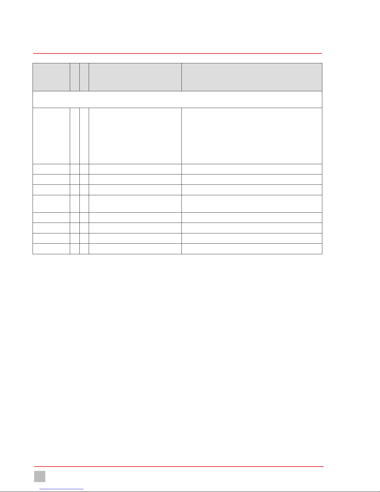
11 Troubleshooting
See below for information about how to rectify faults on the device or the system. If you cannot eliminate the fault, please consult with the manufacturer
on further measures or return the device for repair.
Fault Possible cause Remedy
The device loses all settings after it has been
disconnected from the network and then
reconnected.
The battery is empty. nCheck that the battery is really empty. To do
so, navigate to the menu System >
Information > System values. You can view
the battery voltage under “Battery”. If the
voltage is under 3 V, change the battery.
nReplace the battery.
The device is off. The power supply has been interrupted. Restore the power supply.
The device fuse is defective. Replace the fuse.
The sensor error is displayed as an alarm. The sensor has not been installed correctly. Ensure that the sensor has been installed
correctly. See section 7.5.
The sensor is not held in the sensor bracket
correctly.
Ensure that the sensor has been installed in the
sensor bracket correctly.
The signal cable to the sensor has a break. Replace the sensor bracket.
Table 16: Troubleshooting

Modbus addresses
25
© Lutz-Jesco GmbH 2018
Subject to technical changes.
180426
BA-40900-02-V01
Gas warning device EASYCON GW Operating instructions
12 Modbus addresses
With a DOUBLE-WORD, the HIGH-WORD is transferred first! Hexadecimal display is shown by a leading “0x”.
Address
Read
Write
Description Meaning
Data that are not channel-related.
4 x Device type + version 0x0550 + (number of channels -1)
A single-channel gas warning device thus has the identification:
0x0550
6 to 8 x Software Version: Transfer: ASCII sign
e.g. 102 is the software version V1.02
10 and 11 x Operating hours
13 x Hardware version
2000 - 2002 x Serial number The information consists of a ASCII sign in HIGH-BYTE and one in
LOW-BYTE
Serial number: 123456 will thus be transferred as
Address 2000: 0x3132
Address 2001: 0x3334
Address 2002: 0x3536
2003 x Status of the digital inputs Shows the logic of the clamps! (Not the configured software function)
The individual bits are assigned directly to the input clamps.
Example: 0x01 means that the first digital inputs (clamps 21 + 22) are
actuated.
2004 x Status digital outputs The individual bits of the output modules.
Example: 0x03 means that the upper relay or the upper optocoupler of
the second output module (from the top) is active.
2008 - 2017 x x Name of the gas warning device Max. 20 characters
Caution!
The evaluation must stop at the first zero (string end).
The individual letters are located in the HIGH-BYTE and LOW-BYTE of
every address. “GW” thus produces:
Address 2008 = 0x4757
Address 2009 = 0x00
The question marks are undefined.
In this case, all other addresses send undefined values.
Table 17: Modbus addresses
Modbus addresses
26
© Lutz-Jesco GmbH 2018
BA-40900-02-V01
Gas warning device EASYCON GW Operating instructions
Address
Read
Write
Description Meaning
Channel-related data. 20 addresses are reserved for every channel.
Start at 2020, 2040, 2060 and 2080.
2020 x Medium n3) Chlorine gas
n5) Chlorine dioxide
n9) Ozone
n15) Temperature
n16) Neutral (0 - 100%)
n254) Free entry
n255) No type
2021 x Value (HIGH-WORD) Two positions after decimal point (215 => 2.15)
2022 x Value (LOW-WORD) Two positions after decimal point (215 => 2.15)
2024 x Temperature value One position after the decimal point (215 => 21.5)
2025 x Temperature unit 0 = °C
1 = °F
2026 x x Limit value 1 (HIGH-WORD) Two positions after decimal point (215 => 2.15)
2027 x x Limit value 1 (LOW-WORD) Two positions after decimal point (215 => 2.15)
2028 x x Limit value 2 (HIGH-WORD) Two positions after decimal point (215 => 2.15)
2029 x x Limit value 2 (LOW-WORD) Two positions after decimal point (215 => 2.15)
Table 17: Modbus addresses

Modbus addresses
27
© Lutz-Jesco GmbH 2018
Subject to technical changes.
180426
BA-40900-02-V01
Gas warning device EASYCON GW Operating instructions
Address
Read
Write
Description Meaning
Further non channel-related data.
2220 - 2223 x Analogue outputs 1 - 4 421 = 4.21 mA
2225 x Alarm status 1 Bit 0 ... 15
The bits are logically transferred: „15, 14 ... 1, 0“
2226 x Alarm status 2 Bit 16 ... 31
The bits are logically transferred: “31, 30 ... 17, 16“
Sensor 1 (limit value 1)
Sensor 2 (limit value 1)
Sensor 3 (limit value 1)
Sensor 4 (limit value 1)
Sensor 1 (limit value 2)
Sensor 2 (limit value 2)
Sensor 3 (limit value 2)
Sensor 4 (limit value 2)
Sensor 1 (sensor error)
Sensor 2 (sensor error)
Sensor 3 (sensor error)
Sensor 4 (sensor error)
Sensor 1 (temperature max)
Sensor 2 (temperature max)
Sensor 3 (temperature max)
Sensor 4 (temperature max)
Sensor 1 (temperature min)
Sensor 2 (temperature min)
Sensor 3 (temperature min)
Sensor 4 (temperature min)
Digital input 1
Digital input 2
Digital input 3
Digital input 4
Digital input 5
Digital input 6
Digital input 7
Digital input 8
Sensor change sensor 1 due
Sensor change sensor 2 due
Sensor change sensor 3 due
Sensor change sensor 4 due
Next service due
Bit:
Bit:
Bit:
Bit:
Bit:
Bit:
Bit:
Bit:
Bit:
Bit:
Bit:
Bit:
Bit:
Bit:
Bit:
Bit:
Bit:
Bit:
Bit:
Bit:
Bit:
Bit:
Bit:
Bit:
Bit:
Bit:
Bit:
Bit:
Bit:
Bit:
Bit:
Bit:
Bit:
0
1
2
3
4
5
6
7
8
9
10
11
12
13
14
15
16
17
18
19
20
21
22
23
24
25
26
27
28
29
30
31
32
Table 17: Modbus addresses

EU Declaration of Conformity
28
© Lutz-Jesco GmbH 2018
BA-40900-02-V01
Gas warning device EASYCON GW Operating instructions
13 EU Declaration of Conformity
(DE) EU-Konformitätserklärung
Hiermit erklären wir, dass das nachfolgend bezeichnete Gerät aufgrund seiner Konzipierung und Bauart sowie in der von uns in Verkehr gebrachten Ausführung
den einschlägigen grundlegenden Sicherheits- und Gesundheitsanforderungen der aufgeführten EU-Richtlinien entspricht. Bei einer nicht mit uns abgestimmten
Änderung am Gerät verliert diese Erklärung ihre Gültigkeit.
(FR) Déclaration de conformité UE
Nous déclarons sous notre propre responsabilité que le produit ci-dessous mentionné répond aux exigences essentielles de sécurité et de santé des directives UE
énumérées aussi bien sur le plan de sa conception et de son type de construction que du modèle que nous avons mis en circulation.
Cette déclaration perdra sa validité en cas d’une modification effectuée sur le produit sans notre accord explicite.
(EN) EU Declaration of Conformity
We hereby certify that the device described in the following complies with the relevant fundamental safety and sanitary requirements and the listed EU regulations
due to the concept and design of the version sold by us.
If the device is modified without our consent, this declaration loses its validity.
(ES) Declaración de conformidad UE
Por la presente declaramos que, dados la concepción y los aspectos constructivos del modelo puesto por nosotros en circulación, el aparato mencionado a continuación cumple con los requisitos sanitarios y de seguridad vigentes de las directivas de la U.E. citadas a continuación.
Esta declaración será invalidad por cambios en el aparato realizados sin nuestro consentimiento.
2014/30/EU
2014/35/EU
Die Schutzziele der Niederspannungsrichtlinie 2014/35/EU wurden gemäß Anhang I, Nr. 1.5.1
der Maschinenrichtlinie 2006/42/EG eingehalten.
The protective aims of the Low Voltage Directive 2014/35/EU were adhered to in accordance
with Annex I, No. 1.5.1 of the Machinery Directive 2006/42/EC.
EU-Richtlinien:
EU directives:
Lutz-Jesco GmbH
Dokumentationsbevollmächtigter:
Authorized person for documentation:
Bezeichnung des Gerätes:
Descripción de la mercancía:
Description of the unit:
Désignation du matériel:
Gaswarngerät
Detector de gas
Gas warning device
Détecteur de fuite de gaz
EASYCON GW Typ:
Type:
Heinz Lutz
Geschäftsführer / Chief Executive Officer
Lutz-Jesco GmbH
Wedemark, 01.05.2018
Lutz-Jesco GmbH
Am Bostelberge 19
30900 Wedemark
Germany
DIN EN ISO 12100:2011-03
DIN EN 61000-4-2:2009-12
DIN EN 61000-4-3:2006 + A1:2008 + A2:2010
DIN EN 61000-4-4:2012
DIN EN 61000-4-5:2014
DIN EN 61000-4-6:2014-08
DIN EN 61000-4-11:2005-02
DIN EN 61000-6-2:2016-05
DIN EN 61000-6-3:2011-09
DIN EN 55016-2-3:2010 + A1:2010
Harmonisierte Normen:
Harmonized standards:
(PT) Declaração de conformidade UE
Declaramos pelo presente documento que o equipamento a seguir descrito, devido à sua concepção e ao tipo de construção daí resultante, bem como a versão
por nós lançada no mercado, cumpre as exigências básicas aplicáveis de segurança e de saúde das directivas CE indicadas.
A presente declaração perde a sua validade em caso de alteração ao equipamento não autorizada por nós.
Designação do aparelho: Aparelho de alerta de gás

Warranty claim
29
© Lutz-Jesco GmbH 2018
Subject to technical changes.
180426
BA-40900-02-V01
Gas warning device EASYCON GW Operating instructions
14 Warranty claim
Warranty claim
Please copy and send it back with the unit!
If the device breaks down within the period of warranty, please return it in a cleaned condition with the complete warranty claim.
Sender
Company: ............................................................................................................... Phone: .................................. Date: ..........................
Address: ....................................................................................................................................................................................................
Contact person: .........................................................................................................................................................................................
Manufacturer order no.: .......................................................................................... Date of delivery: .........................................................
Device type: ............................................................................................................ Serial number: ...........................................................
Nominal capacity / nominal pressure: .........................................................................................................................................................
Description of fault:.....................................................................................................................................................................................
...................................................................................................................................................................................................................
...................................................................................................................................................................................................................
...................................................................................................................................................................................................................
...................................................................................................................................................................................................................
...................................................................................................................................................................................................................
...................................................................................................................................................................................................................
...................................................................................................................................................................................................................
Service conditions of the device
Point of use / system designation:...............................................................................................................................................................
...................................................................................................................................................................................................................
...................................................................................................................................................................................................................
Accessories used (suction line etc.):............................................................................................................................................................
...................................................................................................................................................................................................................
...................................................................................................................................................................................................................
...................................................................................................................................................................................................................
...................................................................................................................................................................................................................
Commissioning (date): ................................................................................................................................................................................
Duty period (approx. operating hours): ........................................................................................................................................................
Please describe the specific installation and enclose a simple drawing or picture of the chemical feed system, showing materials of construction, diameters, lengths and heights of suction and discharge lines.

Index
30
© Lutz-Jesco GmbH 2018
BA-40900-02-V01
Gas warning device EASYCON GW Operating instructions
15 Index
C
Commissioning ................................................................................18
D
Design ...............................................................................................8
Dimensioned drawings ....................................................................11
Dimensions ......................................................................................11
Drillhole dimensions ...................................................................11
Outside dimensions ....................................................................11
E
Electrical installation ........................................................................12
Ethernet ...........................................................................................17
EU Declaration of Conformity ...........................................................28
F
Foreseeable misuse ...........................................................................7
G
General warnings ...............................................................................5
H
Handling instructions
Marking ........................................................................................4
Hazards due to non-compliance with the safety instructions ..............5
I
Installation
Connecting the sensor ................................................................14
Connecting the signal technology ...............................................15
Installation example ...........................................................................8
Installation on the wall .....................................................................12
Intended purpose ...............................................................................7
Intended use ......................................................................................7
Internal fuse ....................................................................................23
M
Maintenance ....................................................................................22
Maintenance intervals ......................................................................22
N
Notes for the Reader ..........................................................................4
O
Operation .........................................................................................21
P
Personnel qualification .......................................................................5
Personnel tasks .................................................................................6
Product description ............................................................................8
Product warranty ...............................................................................7
R
Rating plate .......................................................................................9
S
Safety ................................................................................................5
Scope of delivery ...............................................................................8
Signal words
Explanation ...................................................................................4
Specialist staff ...................................................................................5
T
Technical data .................................................................................10
Terminal connection .........................................................................13
Trained electricians ............................................................................5
Trained persons .................................................................................6
Trend display ...................................................................................21
Troubleshooting ...............................................................................24
W
Warnings
General warnings .........................................................................5
Marking ........................................................................................4
Warning sign
Explanation ...................................................................................4
Warranty claim ................................................................................29
Working in a safety-conscious manner ..............................................5

31
© Lutz-Jesco GmbH 2018
Subject to technical changes.
180426
BA-40900-02-V01
Gas warning device EASYCON GW Operating instructions

 Loading...