

Page 1
Technical data sheet
Mounting Accessorie s
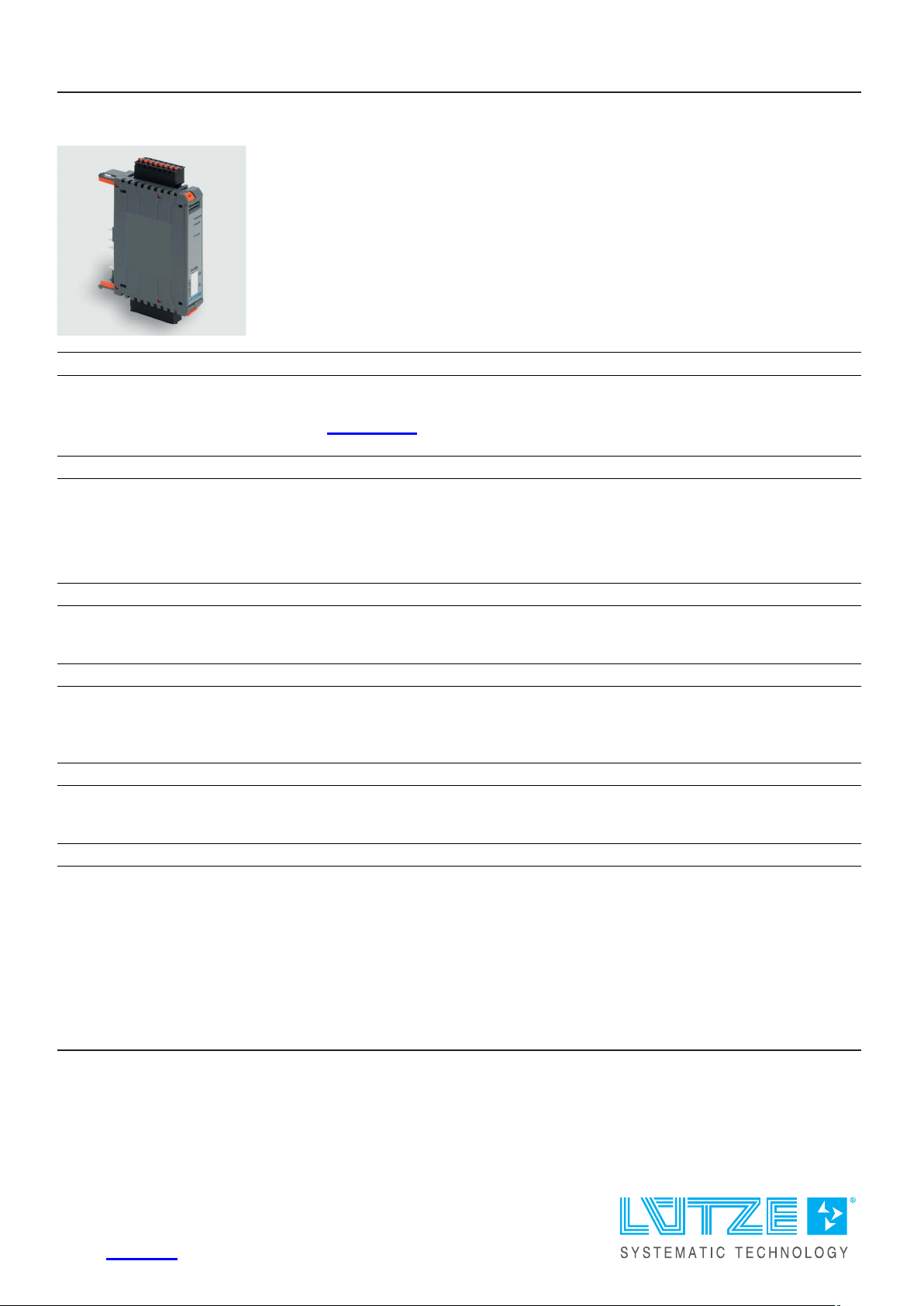
Control unit for AirBLOWER
Identification
Type LCOS-AB-I
Part No.
Product version
Hardware revision 1.0
Software version 1.42
Datasheet version 06
777100.0011
Use/Application/Properties
Application • Control Unit of the AirBLOWER with spring terminal
Description
Description To control the AirBLOWER.
Control unit to be used together with function carrier base.
Configuration interface
HART interface µ-USB Type B 5-pin
Supply module electronic
Rated voltage U
N
DC 24 V SELV
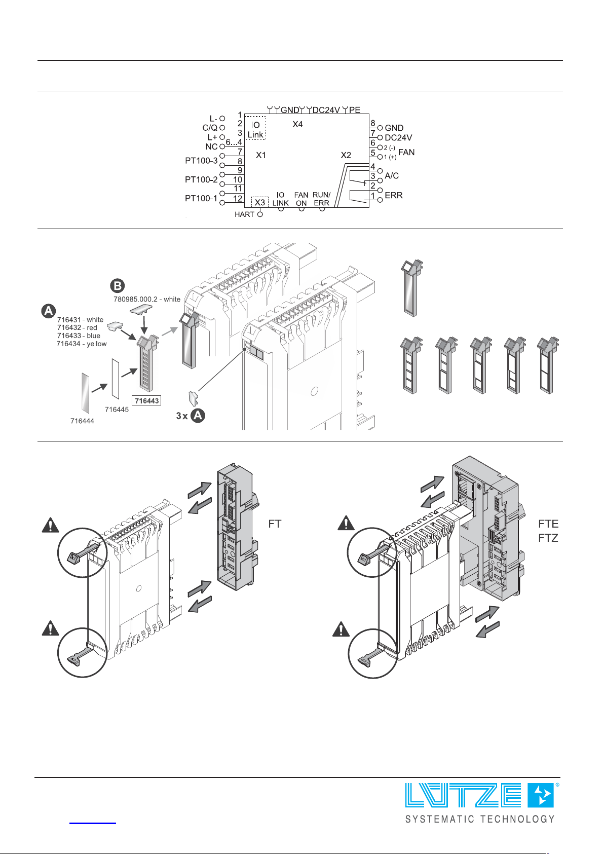
Connection 8-pole Push-In terminal X2: Pin 8–7 or via Powerbus (LCOS system)
use copper conductors only
Rated current DC 2 A
Operation voltage range DC 20.4–28.8 V
United Kingdom: LÜTZE Ltd.
Unit 3, Sandy Hill Park
Sandy Way, Amington • GB-Tamworth, Staffs B77 4DU
Tel. +44 (0)1827 31333-0 • Fax +44 (0)1827 31333-2
www.lutze.com • [email protected]
Germany: Friedrich Lütze GmbH
Postfach 12 24 (PLZ 71366) • Bruckwiesenstraße 17-19 • D-71384 Weinstadt
Tel. +49 (0)7151 6053-0 • Fax +49 (0)7151 6053-277(-288)
www.luetze.de • [email protected]
30.01.2024 • Subject to technical modification
Part No.
777100.0011 • Datasheet version: 06 page 1 of 6
Page 2
Technical data sheet
Mounting Accessorie s
Protective measure Reverse diode
galvanic isolation between module electronic and diagnosis outputs
Overvoltage protection
Diagnosis outputs
Style Switching capacity for EN 60947-5-1 at AC 230 V
dry NC contact for activating the Air conditioning unit
1 A @ 230 V cos phi = 0.75 – 0.8 (General Use)
dry NO contact for Error message
2 A @ 230 V cos phi = 0.75 – 0.8 (General Use)
Connection
Isolating voltage AC 2500 V
Parameterisation HART interface / IO-Link interface
Temperature inputs
Input signal 3 × PT100
Temperature range -50 °C . . . +100 °C
Accuracy +/- 3 K
Connection 12-pole Push-In term i n a l X1: Pin 7-12
Linearization method linear interpolation
8-pole Push-In terminal X2: Pin 1-2 (Relay fault), Pin 3-4 (Relay air
conditioning unit)
Control output
Connection 8-pole Push-In termi n a l X2: Pin 5–6
Style Semi-conductor switch
Switching capacity DC 24 V, 2 A
Diagnostics
LED mode green – OK
red - Fault
green flashing – operating time of the fan exceeded
LED IO-Link green flashing - active
green – connected
orange - fault
Actuator sensor interface
Style IO-Link Device/Slave
Connection 12-pole Push-In term i n a l X1: Pin 1–3
Data rate 38.4 kBaud
Technical data
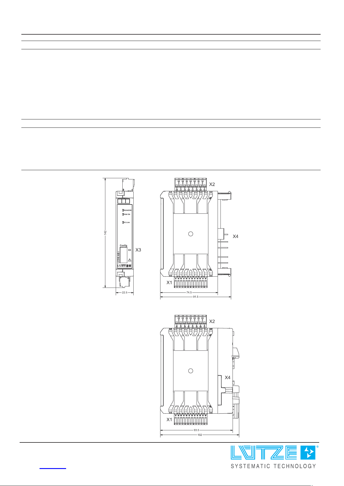
Width 22.5 mm
Depth 91.5 mm
Height 142 mm
30.01.2024 – Subject to technical modification
Part No. 777100.0011 • Datasheet version: 06 page 2 of 6
Page 3

Technical data sheet
Mounting Accessorie s
General
Dimensions (w × h × d) 22.5 mm × 142.0 mm × 91.5 mm
Dimensions with function carrier:
22.5 × 142.0 × 102.0 mm
Relative air humidity 100 %, no condensation allowed
Max. altitude operation 2000 m max.
Mounting DIN rail mounting
Housing material PA 6.6 (UL 94 V-0, NFF I2, F2)
Operation temperature range -25 °C . . . +60 °C
Storage temperature range -40 °C . . . +70 °C
Installation position Vertical
Typical power supply Mains adapter DC 24 V regulated/unreg u l a te d , SELV
System behavior
Max. allowed interruption time of the
power supply
Memory buffer time for configuration
and error data
Self-test and diagnosis possibilities Power-up test: EEPROM test
Accuracy of the current measurement
at the fan output
Degree of protection IP20
Degree of pollution 2
Weight/unit 0.12 kg
PU (units) 1
for typical consequences of power supply interruptions and the return of
power:
Start process with EEPROM test
The number of start processes is unlimited.
PS2 (10 ms)
Supply-independent memory in EEPROM
Periodical test:
Over and under-voltage supply
Sensor error
Over Temperature
Short circuit, interruption and overload of fan outlet
+/- 0.1 A
Certifications/Standards
Conformity CE
UKCA
Certifications cULus (E170585)
DNV (TAA00002SY)
Standards EN 61131-2:2007, EMV, Zone B
EMV according to EN 61131-2 only in combination with 777000.1011
(AirBLOWER fan bank)
UL 61010-1
UL 61010-2-201
DNVGL-CG-0339
30.01.2024 – Subject to technical modification
Part No. 777100.0011 • Datasheet version: 06 page 3 of 6
Page 4
Technical data sheet
Mounting Accessorie s
Equipment/Spare parts
Accessories PT 100 Elements (3 units): Part.-No. 773900.0001 | PU: 1 unit
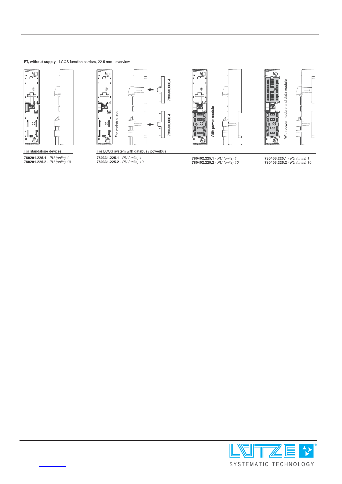
Function carrier 22.5 mm, cannot be expanded with modules
(standalone version): Part.-No. 780201.225.1 | LCOS-FT-PE-225-00-00-1 |
PU: 1 unit
Function carrier 22.5 mm, can be expanded with modules: (in LCOS
system with Powerbus): Part.-No. 780402.225.1 | LCOS-FT-PE-225-0P-
02-1 | PU: 1 unit
See also the appropriate chapter in operating instructions.
Notes and Comments
Note
Dimensions
For the parameterization you need the USB service cable, LCON ZB USB,
part number 750894 and the software Lütze HART-DTM and PACTware.
The current versions can be found in the download area of the respective
product page on the LÜTZE website.
30.01.2024 – Subject to technical modification
Part No.
777100.0011 • Datasheet version: 06 page 4 of 6
Page 5
Technical data sheet
Mounting Accessorie s
PIN assignment
Use
Use
30.01.2024 – Subject to technical modification
Part No. 777100.0011 • Datasheet version: 06 page 5 of 6
Page 6
Technical data sheet
Mounting Accessorie s
Use
30.01.2024 – Subject to technical modification
Part No.
777100.0011 • Datasheet version: 06 page 6 of 6
 Loading...