

Page 1
Technical data sheet
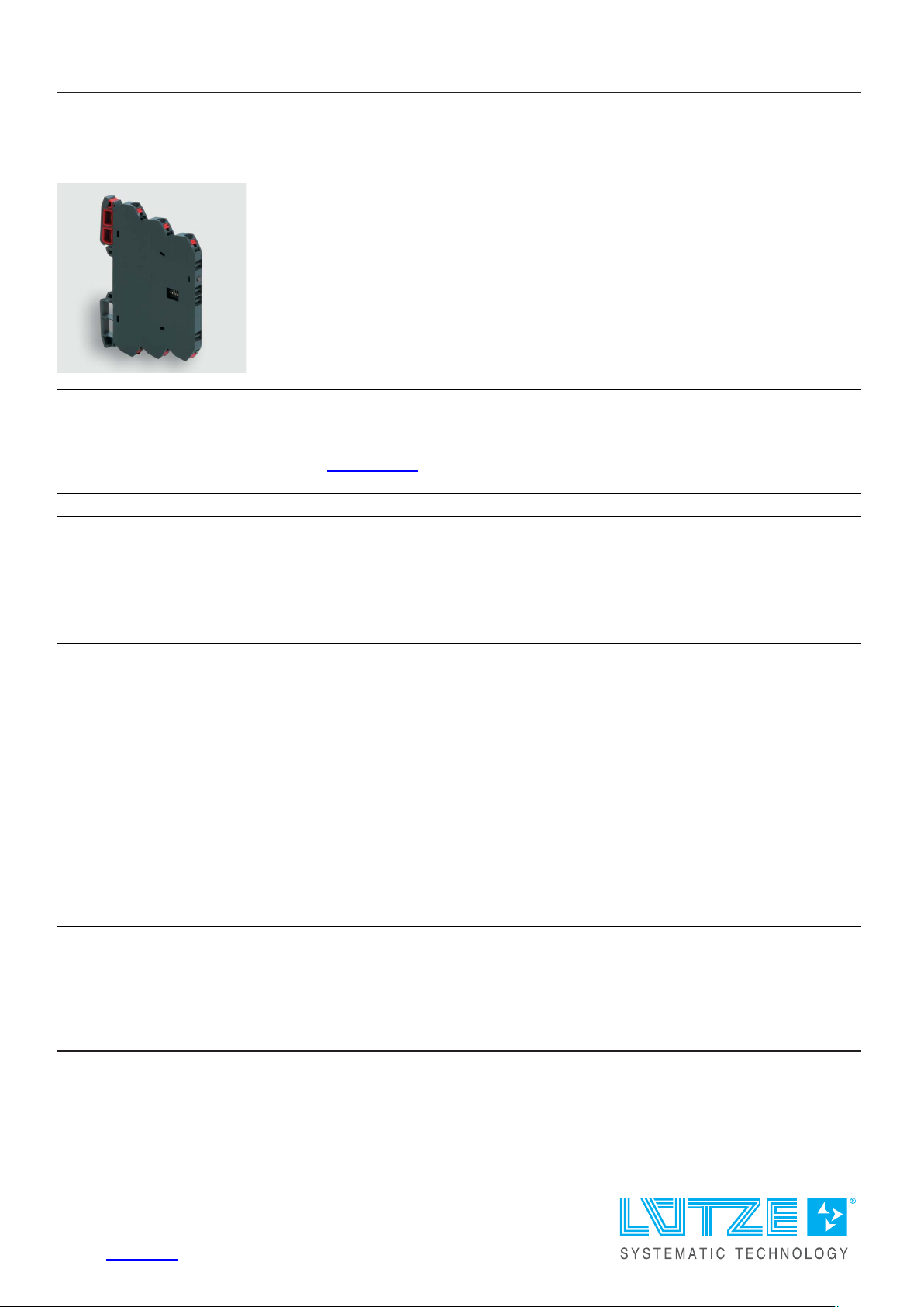
Interface Technology · LCIS temperature/analog converter
Input: PT100, 2-wire
Output: 0–10 V / 0–20 mA / 4–20 mA
Insulation: 2.5 kV, 3-way isolation
Identification
Type LCIS-WPT2LA-1809-62-PI
Part No.
Product version
751809.0000
Hardware revision 1.0
Software version 1.0
Datasheet version 01
Input
Input variable Temperature sensor PT100
Galvanic isolation I/O 3-way isolation
Measuring procedure 2-wire, constant current
Temperature range
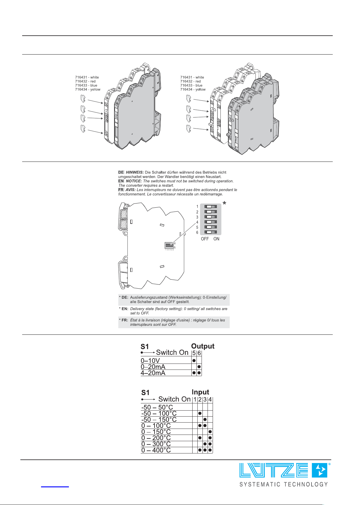
-50 °C–50 °C / -50 °C–100 °C / -50 °C–150 °C / 0 °C–100 °C / 0 °C–1 5 0 °C /
0 °C–200 °C / 0 °C–300 °C / 0 °C – 4 0 0 °C
Parameterisation DIP switch S1
Zero /Span Production comparison
Input resistance >1 MΩ
Sensor current 0.5 mA
Protection device Input Overvoltage protection
Output
Output signal 0–10 V, 0 – 2 0 mA, 4–2 0 mA
Max. load impedance at I-output 500 Ω
Min. load impedance at U-output 2 kΩ
Load deviation at U-output max. 5 mV @ 2 kΩ
United Kingdom: LÜTZE Ltd.
Unit 3, Sandy Hill Park
Sandy Way, Amington • GB-Tamworth, Staffs B77 4DU
Tel. +44 (0)1827 31333-0 • Fax +44 (0)1827 31333-2
www.lutze.com • [email protected]
Germany: Friedrich Lütze GmbH
Postfach 12 24 (PLZ 71366) • Bruckwiesenstraße 17-19 • D-71384 Weinstadt
Tel. +49 (0)7151 6053-0 • Fax +49 (0)7151 6053-277(-288)
www.luetze.de • [email protected]
12.12.2023 • Subject to technical modification
Part No.
751809.0000 • Datasheet version: 01 page 1 of 4
Page 2

Technical data sheet
Interface Technology · LCIS temperature/analog converter
Output voltage <16 V @ 0–20 mA, 4–20 mA
Output current max. 5 mA @ 1 0 V
Residual ripple <20 mV
Parameterisation DIP switch S1
Protection device short circuit protection
Operating data
Accuracy 0.3 % FSR @ 2 3 °C
Linearity error 0.1 % FSR
Rise time (10-90%) approx. 30 ms @ 23 °C
Build-up time (Accuracy 1%) approx. 60 ms @ 23 °C
Temperature coefficient 150 ppm / K FSR
Critical frequency 10 Hz @ 3 dB / 23 °C
Error coefficient of measuring line 2.7 K/Ω
General
eff
Rated voltage U
N
AC/DC 24 V
Rated current approx. 22 mA @ AC 24 V / approx. 13 mA @ DC 24 V
Status indication LED green
Insulation voltage input / output 2.5 kV
eff
Housing material PA 6.6 (UL 94 V-0, NFF I2, F2)
Color of the housing RAL 7012
basalt grey
Mounting DIN rail mountable TS35
(EN 60715)
Degree of protection IP20
Installation position Any
Connection type Push-In
single wire
0.25 mm² – 2.5 mm² / AWG 24–14
fine stranded wire with ferrule
0.25 mm² – 1.5 mm² / AWG 24–16
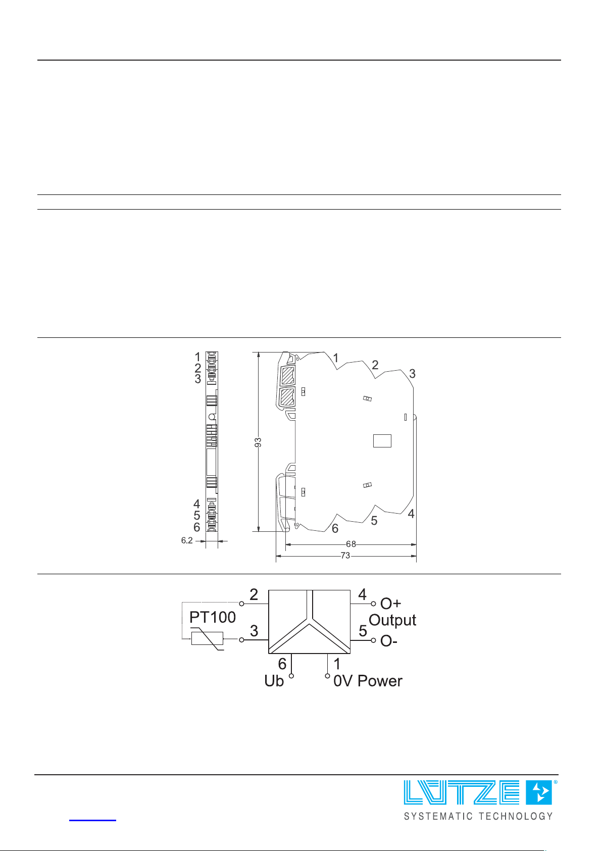
Dimensions (w × h × d) 6.2 mm × 93.0 mm × 73.0 mm
Weight/unit 0.03 kg
PU (units) 1
General ambient conditions
Operation temperature range -25 °C . . . +60 °C
Storage temperature range -40 °C . . . +85 °C
Relative air humidity 20 – 90 % RH, not condensing
Vibration resistance 0.7 g acc. to EN 60 0 6 8 - 2 - 6
Failure Rate Prediction (MTBF)
Standards
Electronic components – Reliab i l i ty – Reference conditions for failure rates
and stress models for conversion: EN/IEC 61709
Failure Rates of Components – Expected values: SN 29500
12.12.2023 – Subject to technical modification
Part No.
751809.0000 • Datasheet version: 01 page 2 of 4
Page 3
Technical data sheet
Interface Technology · LCIS temperature/analog converter
Failure rate at +45 °C 566 fit
Failure rate at +45 °C 1765795 h
1 fit equals one failure per 109component hours
The indicated temperature is the mean component ambient temperature.
Comments The results are valid under following conditions:
Automotive environment or ind u str i a l areas without extreme dust levels and
harmful substances
Continuous operation 8760 h per year
Certifications/Standards
Conformity CE
UKCA
Certifications cULus (E135145)
DNV (TAA000024Y)
Standards EN 60947-1
EN 60947-5-1
UL 508
DNV-CG-0339
Dimensions
PIN assignment
12.12.2023 – Subject to technical modification
Part No. 751809.0000 • Datasheet version: 01 page 3 of 4
Page 4
Technical data sheet
Interface Technology · LCIS temperature/analog converter
Use
Use
Range adjustment
12.12.2023 – Subject to technical modification
Part No.
751809.0000 • Datasheet version: 01 page 4 of 4
 Loading...