

Page 1
Technical data sheet
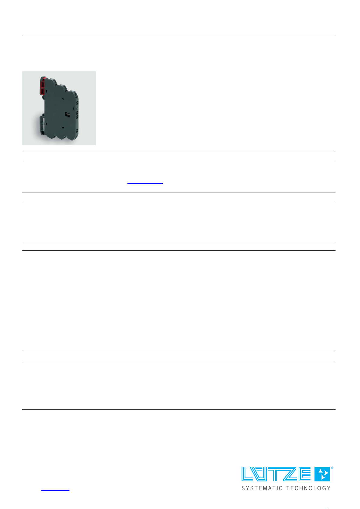
Interface Technology · LCIS temperature/analog converter
Input: PT100, 2-wire
Output: 0–10 V / 0–20 mA / 4–20 mA
Insulation: 2.5 kV, 3-way isolation
Identification
Type LCIS-WPT2LA-0809-62-S
Part No.
Product version
750809.0000
Hardware revision 1.0
Software version 1.0
Datasheet version 01
Input
Input variable Temperature sensor PT100
Galvanic isolation I/O 3-way isolation
Measuring procedure 2-wire, constant current
Temperature range
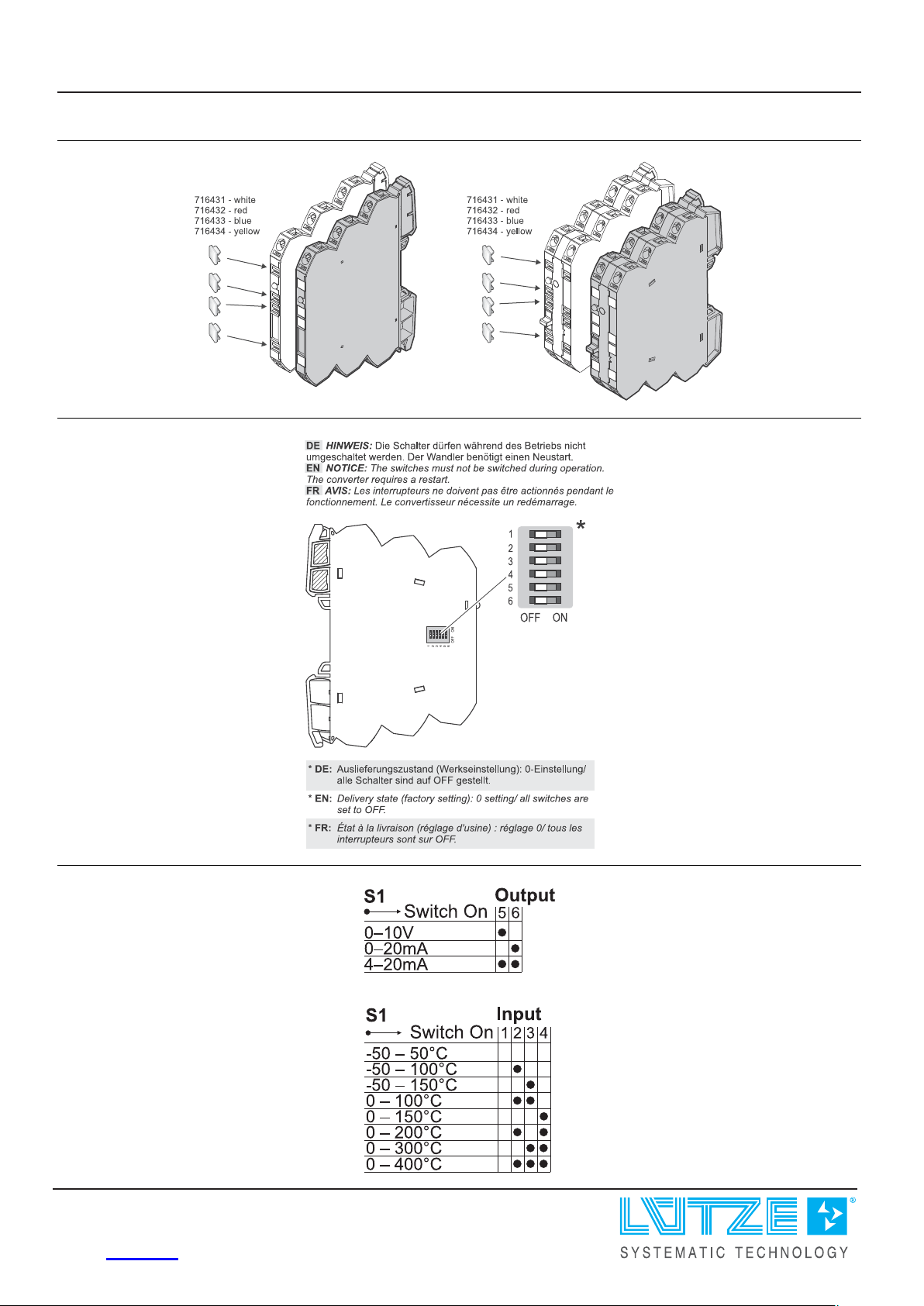
-50 °C–50 °C / -50 °C–100 °C / -50 °C–150 °C / 0 °C–100 °C / 0 °C–1 5 0 °C /
0 °C–200 °C / 0 °C–300 °C / 0 °C – 4 0 0 °C
Parameterisation DIP switch S1
Zero /Span Production comparison
Input resistance >1 MΩ
Sensor current 0.5 mA
Protection device Input Overvoltage protection
Output
Output signal 0–10 V, 0 – 2 0 mA, 4–2 0 mA
Max. load impedance at I-output 500 Ω
Min. load impedance at U-output 2 kΩ
Load deviation at U-output max. 5 mV @ 2 kΩ
United Kingdom: LÜTZE Ltd.
Unit 3, Sandy Hill Park
Sandy Way, Amington • GB-Tamworth, Staffs B77 4DU
Tel. +44 (0)1827 31333-0 • Fax +44 (0)1827 31333-2
www.lutze.com • [email protected]
Germany: Friedrich Lütze GmbH
Postfach 12 24 (PLZ 71366) • Bruckwiesenstraße 17-19 • D-71384 Weinstadt
Tel. +49 (0)7151 6053-0 • Fax +49 (0)7151 6053-277(-288)
www.luetze.de • [email protected]
12.12.2023 • Subject to technical modification
Part No.
750809.0000 • Datasheet version: 01 page 1 of 4
Page 2

Technical data sheet
Interface Technology · LCIS temperature/analog converter
Output voltage <16 V @ 0–20 mA, 4–20 mA
Output current max. 5 mA @ 1 0 V
Residual ripple <20 mV
Parameterisation DIP switch S1
Protection device short circuit protection
Operating data
Accuracy 0.3 % FSR @ 2 3 °C
Linearity error 0.1 % FSR
Rise time (10-90%) approx. 30 ms @ 23 °C
Build-up time (Accuracy 1%) approx. 60 ms @ 23 °C
Temperature coefficient 150 ppm / K FSR
Critical frequency 10 Hz @ 3 dB / 23 °C
Error coefficient of measuring line 2.7 K/Ω
General
eff
Rated voltage U
N
AC/DC 24 V
Rated current approx. 22 mA @ AC 24 V / approx. 13 mA @ DC 24 V
Status indication LED green
Insulation voltage input / output 2.5 kV
eff
Housing material PA 6.6 (UL 94 V-0, NFF I2, F2)
Color of the housing RAL 7012
basalt grey
Mounting DIN rail mountable TS35
(EN 60715)
Degree of protection IP20
Installation position Any
Connection type Screwed terminal
single wire
0.25 mm² – 2.5 mm² / AWG 24–14
fine stranded wire with ferrule
0.25 mm² – 1.5 mm² / AWG 24–16
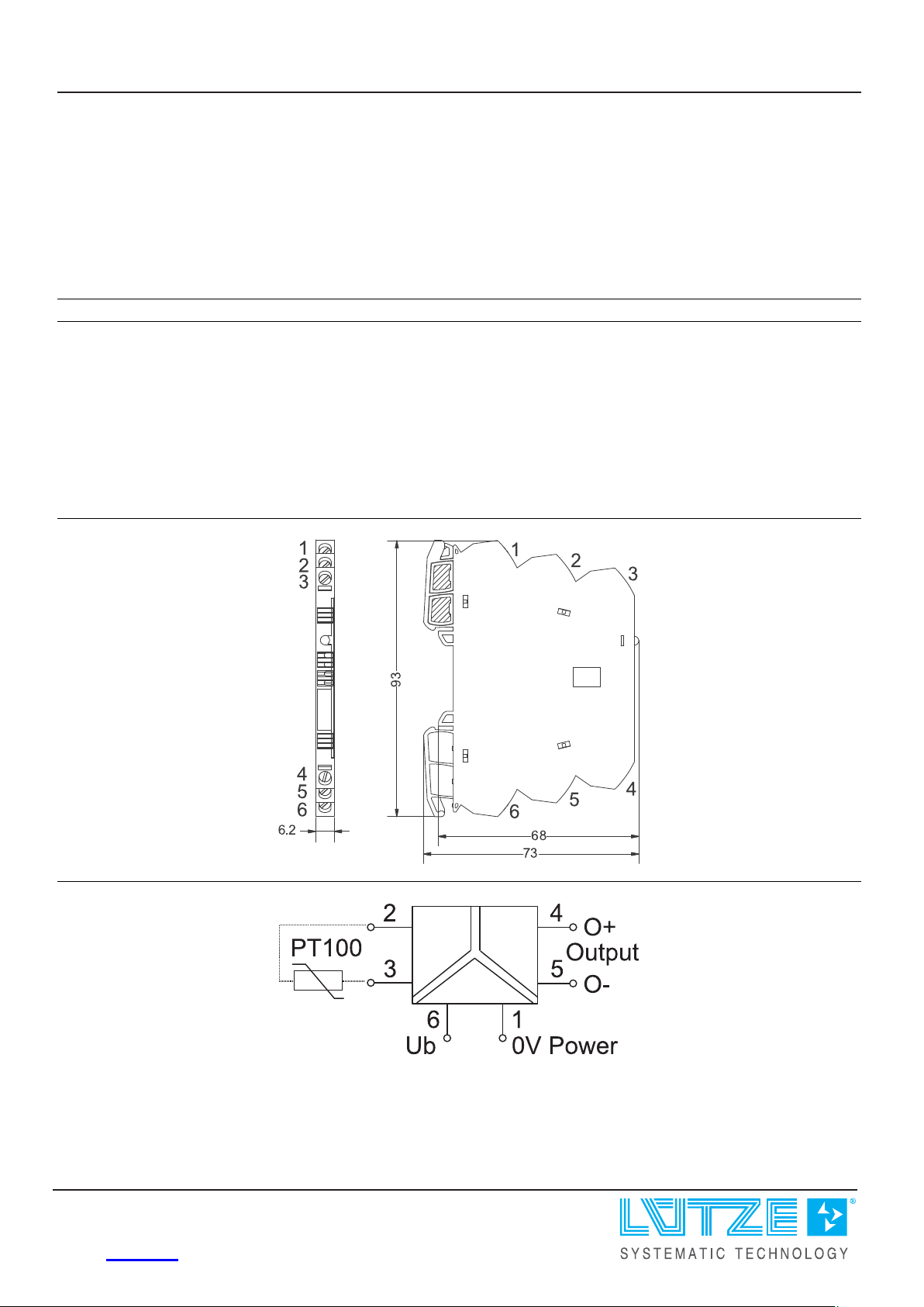
Dimensions (w × h × d) 6.2 mm × 93.0 mm × 73.0 mm
Weight/unit 0.03 kg
PU (units) 1
General ambient conditions
Operation temperature range -25 °C . . . +60 °C
Storage temperature range -40 °C . . . +85 °C
Relative air humidity 20 – 90 % RH, not condensing
Vibration resistance 0.7 g acc. to EN 60 0 6 8 - 2 - 6
Failure Rate Prediction (MTBF)
Standards
Electronic components – Reliab i l i ty – Reference conditions for failure rates
and stress models for conversion: EN/IEC 61709
Failure Rates of Components – Expected values: SN 29500
12.12.2023 – Subject to technical modification
Part No.
750809.0000 • Datasheet version: 01 page 2 of 4
Page 3
Technical data sheet
Interface Technology · LCIS temperature/analog converter
Failure rate at +45 °C 566 fit
Failure rate at +45 °C 1765795 h
1 fit equals one failure per 109component hours
The indicated temperature is the mean component ambient temperature.
Comments The results are valid under following conditions:
Automotive environment or ind u str i a l areas without extreme dust levels and
harmful substances
Continuous operation 8760 h per year
Certifications/Standards
Conformity CE
UKCA
Certifications cULus (E135145)
DNV (TAA000024Y)
Standards EN 60947-1
EN 60947-5-1
UL 508
DNV-CG-0339
Dimensions
PIN assignment
12.12.2023 – Subject to technical modification
Part No. 750809.0000 • Datasheet version: 01 page 3 of 4
Page 4
Technical data sheet
Interface Technology · LCIS temperature/analog converter
Use
Use
Range adjustment
12.12.2023 – Subject to technical modification
Part No.
750809.0000 • Datasheet version: 01 page 4 of 4
 Loading...