

Page 1
Technical data sheet
Interface Technology · Microcompact temp./analog converter
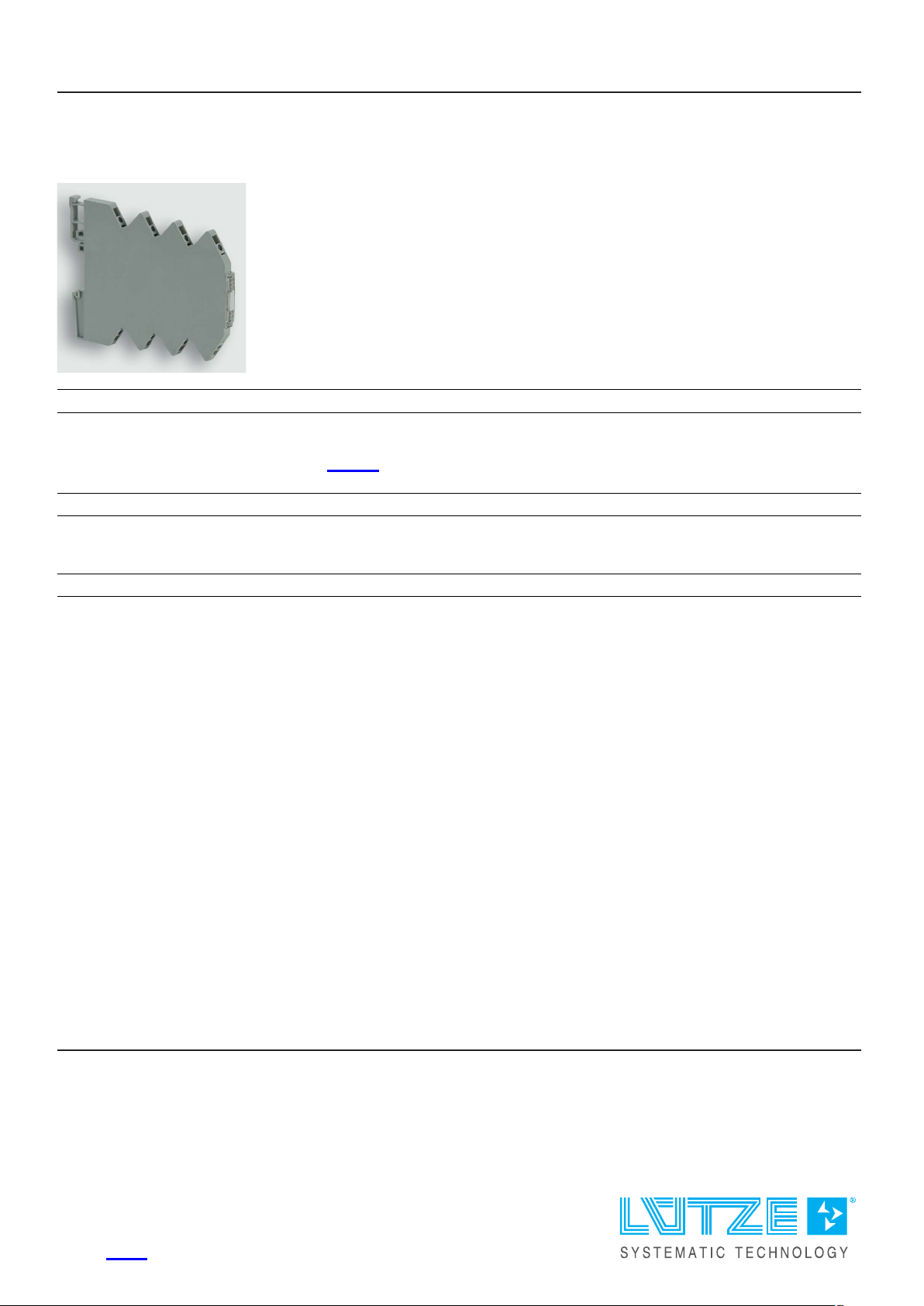
Input: PT, thermocouple, potentiometer – adjustable temperature converter
Output: 0–20 mA / 4–20 mA / 0–10 V / -10–10 V / 2–10 V / 0–5 V / 1–5 V
Insulation: 2.5 kV, 3-way isolation
Identification
Type LCON TA DFDT 806210
Part No.
Product version
750340
Datasheet version 02
Input
Input variable PT100
2/3/4 conductor
PT1000
Resistor
Type B
Type C
Type E
Type J
Type K
Type N
Type R
Type S
Type T
Measurement input PT100, PT1000, resistencia, potenciómetro
Thermal elements: Type B, C, E, J, K, N, R, S, T
Customer-specific via support points, polynomial
Galvanic isolation I/O 3-way isolation
Step response (10–90%)
TE: 10 ms–550 ms, PT: 5–550 ms (adjustable by means of filter stage 1–5,
default: filter stage 4 = 100 ms)
Temperature range PT: -220 . . . 850 °C depending on type
Thermal elements: -210 . . . 2310 °C depending on type
United Kingdom: LÜTZE Ltd.
Unit 3, Sandy Hill Park
Sandy Way, Amington • GB-Tamworth, Staffs B77 4D U
Tel. +44 (0)1827 31333-0 • Fax +44 (0)1827 31333-2
www.lutze.com • [email protected]
Germany: Friedrich Lütze GmbH
Postfach 12 24 (PLZ 71366) • Bruckwiesenstraße 17-19 • D-71384 Weinstadt
Tel. +49 (0)7151 6053-0 • Fax +49 (0)7151 6053-277(-288)
www.luetze.de • [email protected] e
27.06.2023 • Subject to technical modification
Part No.
750340 • Datasheet version: 02 page 1 of 5
Page 2

Technical data sheet
Interface Technology · Microcompact temp./analog converter
Parameterisation Software FDT/DTM
DIP switch
Input resistance Thermocouples: 1 MΩ
Sensor current PT, potentiometer, resistance: 0.002–0.6 mA depending on type
Circuit
Output
PT - 2, 3, 4-wire, for 2-wire with offset correction, no external bridges
necessary, autom. detection
Output signal
0–10 V, -10–10 V, 0–20 mA, 4–20 mA adjustable via switch and software
FDT/DTM, connection via USB service cable
Max. load impedance at I-output 700 Ω @ 0–20 mA, 4–20 mA
Max. load impedance at U-output >2 kΩ @ 0 – 1 0 V, -10–10 V
Limitation for exce e d i n g
measurement range
Max. mo d u l a ti o n range/outp u t signal/
output current
10.25 V @ 0–10 V, -10–10 V
20.5 mA @ 0–20 mA, 4–20 mA
10.5 V @ 0–10 V, -10–10 V
21 mA @ 0–20 mA, 4–20 mA
Parameterisation Software FDT/DTM
DIP switch
Operating data
Accuracy PT: 10 K, d i vi d e d by the set measu r e m e n t ran g e (K) + 0.2 % FSR
Thermocouples: 10 K, divided by the set measurement range (K) + 0.4 %
FSR
Linearity error ±0.1 % FSR
General
Rated voltage U
N
DC 24 V
Rated current approx. 18 mA
Status indication LED green, red (error)
Input/output protection Overvoltage DC 30 V, short circuit-proof output
Temperature error <100 ppm/K FSR
Data storage Flash
Insulation voltage input / output 2.5 kV
eff
Resolution 16-bit
Temperature compensation internally Thermal elements: type ±1 K , max. ±2 K
Configuration Switch and software: FDT / DTM
Housing material PA 6.6 (UL 94 V-0)
Color of the housing light grey
Mounting DIN rail mountable TS35
(EN 60715)
Degree of protection IP20
Installation position Any
Connection type Screw terminal
0.14 mm² – 1.5 mm²
Dimensions (w × h × d) 6.2 mm × 90.0 mm × 115.5 mm
Weight/unit 0.05 kg
PU (units) 1
27.06.2023 – Subject to technical modification
Part No. 750340 • Datasheet version: 02 page 2 of 5
Page 3

Technical data sheet
Interface Technology · Microcompact temp./analog converter
General ambient conditions
Operation temperature range -40 °C . . . +70 °C
Storage temperature range -40 °C . . . +85 °C
Relative air humidity 10 % – 95 %, without condensation
Vibration resistance 4 g acc. to EN 60 0 6 8 - 2 - 6
Shock resistance 15 g acc. EN 60068-2-27
Failure Rate Prediction (MTBF)
Standards
Failure rate at +45 °C 678 fit
Failure rate at +45 °C 1474689 h
Comments The results are valid under following conditions:
Certifications/Standards
Conformity CE
Certifications cULus (E135145)
Standards EN 60947-1
Electronic components – Relia b i l i ty – Reference conditions for failure rates
and stress models for conversion: EN/IEC 61709
Failure Rates of Components – Expected values: SN 29500
1 fit equals one failure per 109component hours
The indicated temperature is the mean component ambient temperature.
Automotive environment or in d u str i a l areas without extreme dust levels and
harmful substances
UKCA
cULus (E319134) use in Class I, Div. 2, Hazardous Locations
EN 60947-5-1
UL 508
UL 121201
DNVGL-CG-0339
Temperature Class D – not certified
Humidity Class B – not certified
Vibration Class B – not certified
EMC Class A – not certified
Enclosure Class A – not certified
Equipment/Spare parts
Accessories Jumper comb 6 A (VE 10)
2-pin: 762802 (red), 762803 (white), 762804 (blue)
3-pin: 762805 (red), 762806 (white), 762807 (blue)
4-pin: 762812 (red), 762813 (white), 762814 (blue)
8-pin: 762822 (red), 762823 (white), 762824 (blue)
16-pin: 762832 (red), 762833 (white), 762834 (blue)
Marker holder 4×11 mm white, Part-No. 681313, PU: 100 units
Laser label 4.23×11 mm (sheet with 1056 labels), Part-No. 681034, PU:
1 unit
27.06.2023 – Subject to technical modification
Part No. 750340 • Datasheet version: 02 page 3 of 5
Page 4
Technical data sheet
Interface Technology · Microcompact temp./analog converter
Notes and Comments
Note
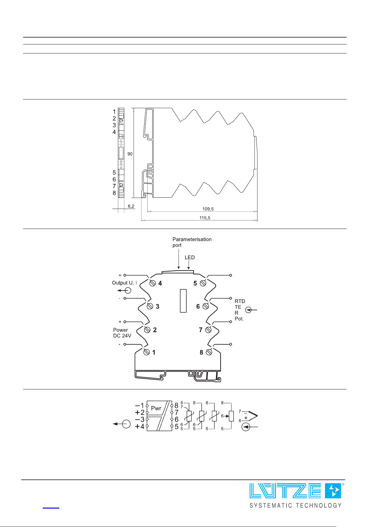
Dimensions
PIN assignment
For the parameter i za ti o n you need the USB service cable, LCON ZB USB,
part number 750894 and the software Lütze HART-DTM and PACTware.
The cur r e n t versions can be found in the download area of the respective
product page on the LÜTZE website.
PIN assignment
27.06.2023 – Subject to technical modification
Part No. 750340 • Datasheet version: 02 page 4 of 5
Page 5
Technical data sheet
Interface Technology · Microcompact temp./analog converter
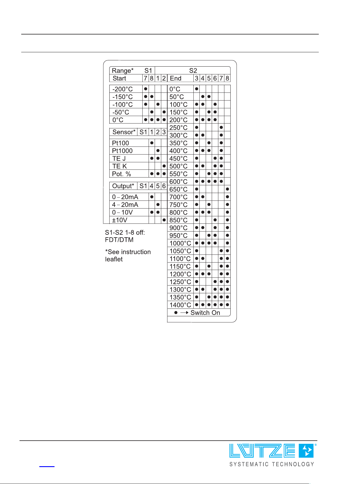
Range adjustment
27.06.2023 – Subject to technical modification
Part No.
750340 • Datasheet version: 02 page 5 of 5
 Loading...