

Page 1
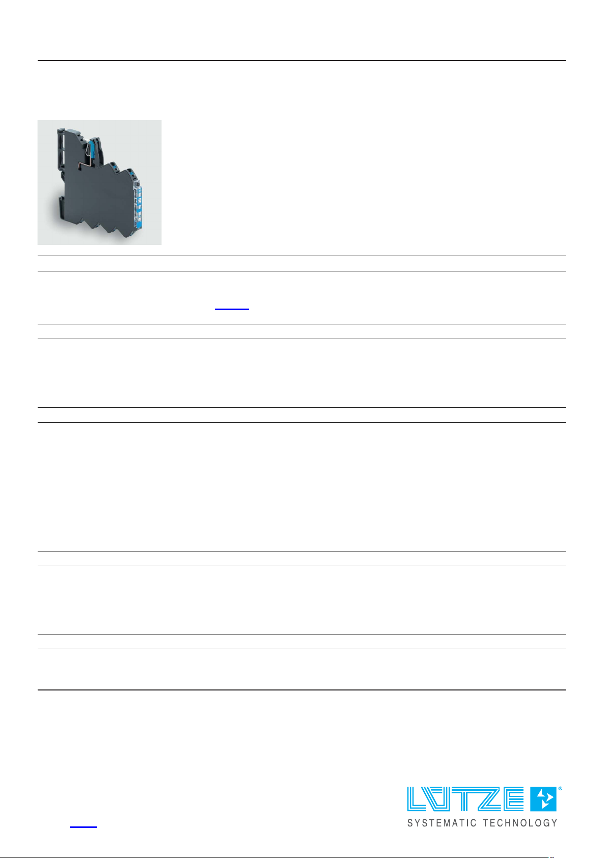
Technical data sheet
Load monitoring · LOCC-Box-C2
Electronic load monitoring up to DC 24 A - DC 4 A
Single channel version, adjustable current range, adjustable characteristic
with current limitation acc. to NEC class 2
Identification
Type LOCC-Box-C2 7-6413
Part No.
Product version
716413
Hardware revision 2.0
Software version 2.3
Datasheet version 01
Input
Type of function 1-channel 1 pin switching
Rated voltage U
N
DC 12/24 V
Operation voltage range DC 11–30 V
Rated current I
N
DC 5 A
Supply current DC 40 A over Cu-rails 10 × 3 mm
Reverse voltage protection internal electronics
Connection type input screwless contact slide
Control input (Set / Reset)
Signal level DC 12/24 V acc. to EN 61131
OFF Pulse with falling edge >100 ms, <800 ms
ON Pulse with falling edge > 1 s
Output
Switching element MOSFET
United Kingdom: LÜTZE Ltd.
Unit 3, Sandy Hill Park
Sandy Way, Amington • GB-Tamworth, Staffs B77 4DU
Tel. +44 (0)1827 31333-0 • Fax +44 (0)1827 31333-2
www.lutze.com • [email protected]
Germany: Friedrich Lütze GmbH
Postfach 12 24 (PLZ 71366) • Bruckwiesenstraße 17-19 • D-7138 4 Weinstadt
Tel. +49 (0)7151 6053-0 • Fax +49 (0)7151 6053-277(-288)
www.luetze.de • [email protected]
26.09.2023 • Subject to technical modifica ti o n
Part No.
716413 • Datasheet version: 01 page 1 of 6
Page 2
Technical data sheet
Load monitoring · LOCC-Box-C2
Output current max. DC 4 A
Power output limited to <100 W
Voltage drop max. 275 mV (4 A)
Status display output LED green: operating voltage present, no error
LED red: error in load circuit
Switch-on capacity 4700 µF
Current range 0.5 A – 4 A (can be set via switch in 0.5 A steps)
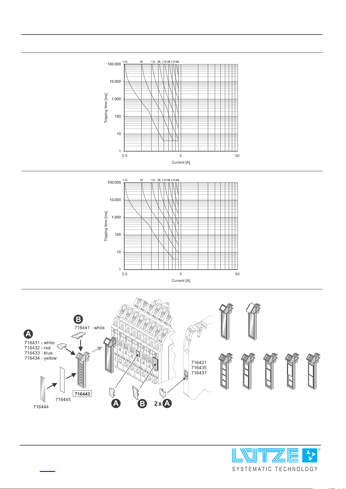
Characteristic fast (1), medium (2), slow 1 (3) see ’Characteristic curves’
Current limitation <5 A
Signal output
Signal level DC 24 V: operating voltage on standby, no e r r o r,
DC 0 V: error, output switched off an d manua l "OFF"
Switching element Transistor, collector with pull-up resistance
General
Dimensions (w × h × d) 8.1 mm × 107.4 mm × 116.0 mm
Housing material PA 6.6 (UL 94 V-0, NFF I2, F2)
Mounting DIN rail mountable TS35
(EN 60715)
Installation position Any
Degree of protection IP20 (only as complete system with power terminal and end block)
Connection type Push-In
0.25 mm² – 2.5 mm²
AWG 24 – AWG 14
Weight/unit 0.07 kg
PU (units) 1
General ambient conditions
Operation temperature range -25 °C . .. +50 °C
Storage temperature range -40 °C . .. +85 °C
Relative air humidity 10 – 95 % RH, brief condensation
Vibration resistance 4 g acc. to EN 60068-2-6
Shock resistance 15 g acc. EN 60068-2-27
Certifications/Standards
Conformity CE
UKCA
Certifications cULus (E170585)
URus (E490188)
26.09.2023 – Subject to technical modification
Part No. 716413 • Datasheet version: 01 page 2 of 6
Page 3
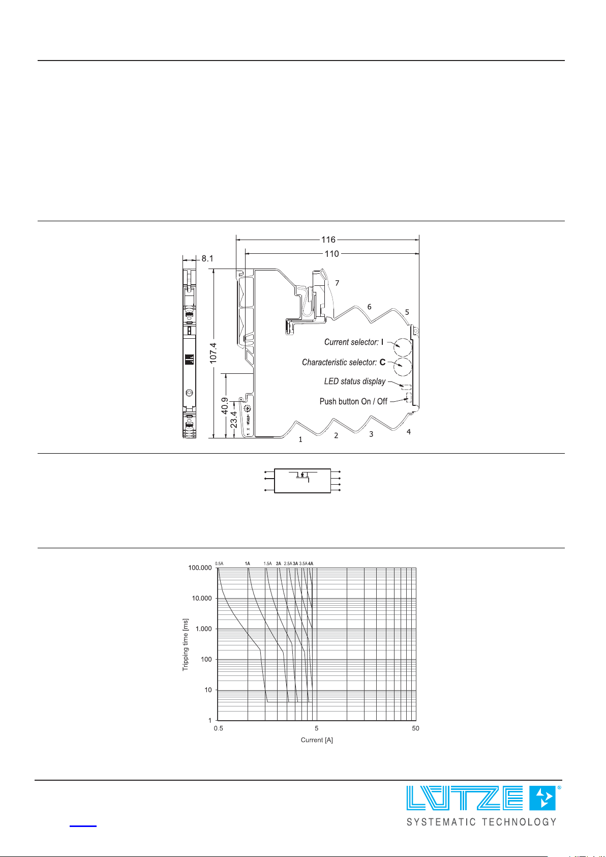
7
DC24V
C-Control
6
5
0V
3
1
Load+
Status
4
NC
DC24V
2
Set/
Reset
1:+Output
2:Controlinput(Set/Reset)
3:Statusoutput
4:NC
5:0V
6:+Supply(alternative)
7:+Supply
Technical data sheet
Load monitoring · LOCC-Box-C2
Standards EN 61000-6-2
EN 61000-6-3
EN 61131-2
UL 61010-1
UL 61010-2-201
UL 2367
DNVGL-CG-0339
Temperature Class C – not certified
Humidity Class B – not certified
Vibration Class B – not certified
EMC Class A – not certified
Dimensions
PIN assignment
1: Characteristic fast
26.09.2023 – Subject to technical modification
Part No. 716413 • Datasheet version: 01 page 3 of 6
Page 4
Technical data sheet
Load monitoring · LOCC-Box-C2
2: Characteristic medium
3: Characteristic slow-1
Use
26.09.2023 – Subject to technical modification
Part No. 716413 • Datasheet version: 01 page 4 of 6
Page 5

Technical data sheet
Load monitoring · LOCC-Box-C2
LED status
Signal output
26.09.2023 – Subject to technical modification
Part No.
716413 • Datasheet version: 01 page 5 of 6
Page 6
Technical data sheet
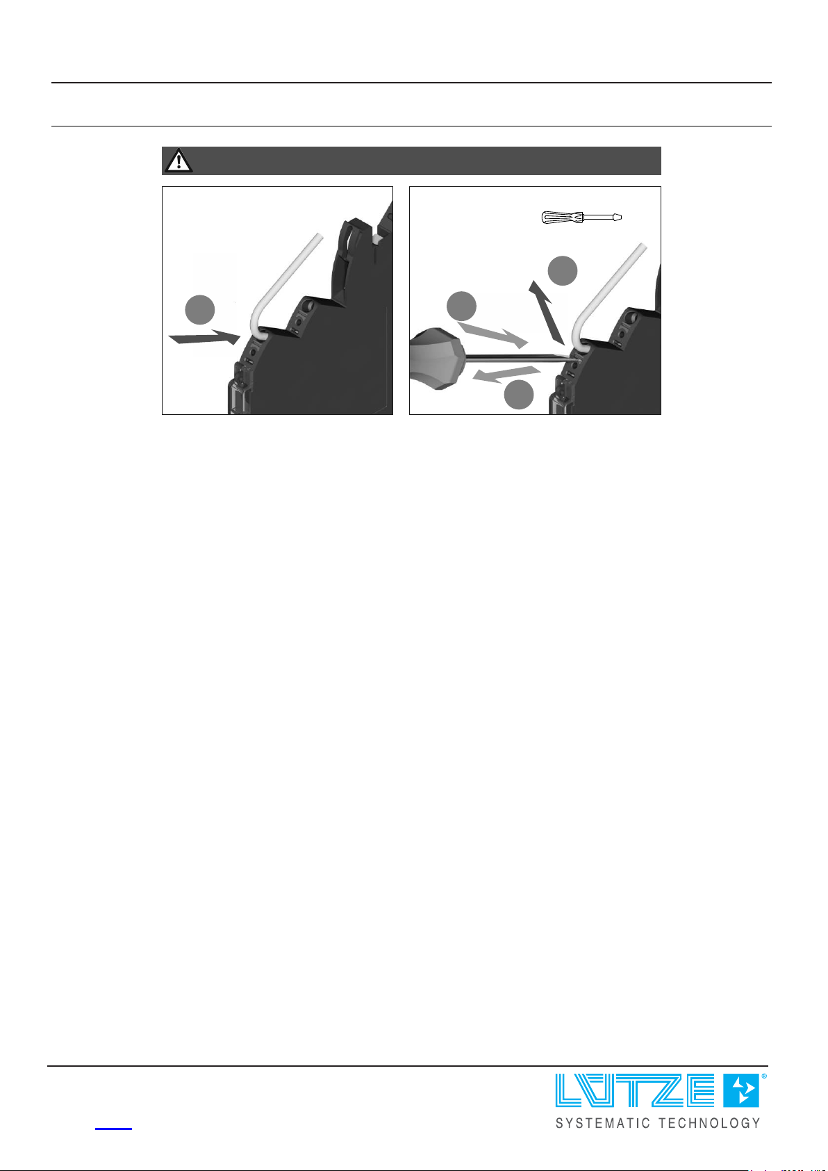
Push-In
1
Push-In
1
2
3
3.5 x 0.5mm
HINWEIS / NOTICE / AVIS
Montage/
Mounting/
Montage
Demontage/
Demounting/
Démontage
Load monitoring · LOCC-Box-C2
Mounting diagram
26.09.2023 – Subject to technical modification
Part No.
716413 • Datasheet version: 01 page 6 of 6
 Loading...