

Page 1
1
D
Vor Inbetriebnahme Betriebsanleitung lesen!
Read this operating instructions before start up!
Für künftige Verwendung aufbewahren.
To be retained for future reference.
Betriebsanleitung 3–6
UNIVERSALMOTORE
MA II / MI 4
Operating Instructions 7–10
UNIVERSAL MOTORS
MA II / MI 4
IP24 IP54
GB
D
Page 2
2
Bild/Fig. 7 (Motor MI 4)
Bild/Fig. 5Bild/Fig. 4 (Motor MI 4)
Bild/Fig. 2
Bild/Fig. 1
Bild/Fig. 3 (Motor MA II)
Bild/Fig. 6 (Motor MA II)
Page 3

3
D
Inhaltsverzeichnis
1. Allgemeines ....................................................................................................... 4
1.1 Lieferumfang ................................................................................................ 4
2. Motorvarianten
.................................................................................................... 4
2.1 Elektrische Ausführung ................................................................................ 4
3. Inbetriebnahme ................................................................................................... 4
3.1 Montage am Pumpwerk ............................................................................... 4
3.2 Elektrischer Anschluss ................................................................................. 4
4. Bedienung ........................................................................................................... 5
4.1 Überstromauslöser ...................................................................................... 5
4.2 Netzausfall und Unterspannungsauslösung (nur MA II) ............................... 5
4.3 Elektronischer Drehzahlsteller (nur MI 4-230 E, MI 4-120 E, MI 4-100 E) ... 5
5. Wartung .............................................................................................................. 5
5.1 Kohlebürsten ................................................................................................ 5
5.2 Wechsel des Netzkabels ............................................................................... 5
6. Reparaturen ........................................................................................................ 5
EG-Konformitätserklärung MA II .........................................................................
11
EG-Konformitätserklärung MI 4 ..........................................................................
11
Page 4
4
D
Allgemeine Sicherheitshinweise
Die Betriebsanleitung ist vor Inbetriebnahme vom
Bediener des Motors zu lesen und die Hinweise
sind während des Betriebs einzuhalten.
1. Der Motor ist nicht explosionsgeschützt. Er darf nicht
in explosionsgefährdeter Umgebung verwendet werden.
2. Es dürfen keine brennbaren Flüssigkeiten gefördert
werden.
3. Die bestimmungsgerechte Gebrauchslage des Motors
ist senkrecht.
4. Der Motor darf nicht in die Förderflüssigkeit getaucht
werden.
5. Beachten Sie, dass alle Anschlüsse und Verbindungen
richtig befestigt sind.
6. Die auf dem Typenschild aufgeführte Spannung muss
mit der Netz-/ Batteriespannung übereinstimmen.
7. Prüfen Sie ob der Motor ausgeschaltet ist, bevor Sie
die elektrische Verbindung herstellen.
8. Überprüfen Sie die Unterspannungsauslösung, wenn
diese für den sicheren Betrieb benötigt wird.
9. Motor nicht ohne Pumpwerk betreiben.
10. Motor nicht über Drehzahlsteller abstellen. Unkon
-
trollierter Wiederanlauf möglich.
Die Unfallverhütungsvorschriften des jeweiligen Landes
sind unbedingt einzuhalten.
1. Allgemeines
Eine elektrische Fass- und Behälterpumpe besteht aus
dem Motor und einem zum jeweiligen Einsatzfall passenden Pumpwerk. Die Motortypen MA II und MI 4
mit den verschiedenen Pumpwerken eignen sich zum
Pumpen nichtbrennbarer, aggressiver, dünnflüssiger Medien. Die Motoren sind nicht zur Verwendung in oder an
Schwimmbecken, Gartenteichen oder ähnlichen Orten
zugelassen.
1.1 Lieferumfang
Prüfen Sie die Lieferung mit Hilfe Ihrer Bestellung auf
Vollständigkeit.
2. Motorvarianten
Die Pumpenmotoren sind Einphasen-Reihenschlussmotoren in Betriebsspannungen, Aufnahmeleistungen
und Frequenzen gemäß Tabelle 1 und 2 (siehe Seite 6).
Die aufgenommene Motorleistung und die erforderliche
Spannung und Frequenz sind dem Typenschild zu entnehmen. Spannung und Frequenz sind auf Übereinstimmung mit dem vorhandenen Netz zu prüfen.
Der Bediener ist Vibrationen ausgesetzt, wenn er den
Motor während des Betriebs in der Hand hält. Die Beschleunigung, der die oberen Körpergliedmaßen ausgesetzt sind liegt unter 2,5 m/s².
2.1 Elektrische Ausführung
Typ
MA II MI 4
zweipoliger Ein-/Ausschalter
einpoliger thermischer
Überstromauslöser
Unterspannungsauslöser Option –
Schutzklasse I
1)
II
Schutzart IP 54 IP 24
1)
Die Motoren MA II 3-12, MA II 5-42 und MA II 5-24
entsprechen Schutzklasse III
3. Inbetriebnahme
3.1 Montage am Pumpwerk
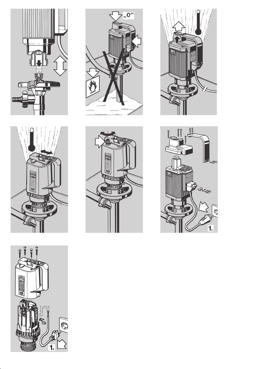
Der Pumpenmotor wird auf das Pumpwerk aufgesetzt.
Hierbei greift der Mitnehmer am Motor in die Kupplung am Pumpwerk ein. Nun werden mit dem Handrad
(Rechtsgewinde) Motor und Pumpwerk fest miteinander
verbunden (siehe Bild 1).
3.2 Elektrischer Anschluss (siehe Bild 2)
Die auf dem Typenschild aufgeführte Spannung muss mit
der Netz-/ Batteriespannung übereinstimmen.
Der Ein-/Ausschalter muss vor dem Netz-/ Batterieanschluss in 0-Stellung sein.
Motortypen für Gleichstrombetrieb können in beliebiger
Polung an die Stromversorgung angeschlossen werden.
Page 5

5
D
4. Bedienung
4.1 Überstromauslöser
Der im Motor eingebaute Überstromauslöser schaltet den
Motor bei Überlastung ab. Nach Abkühlung muss zum
Starten des Motors erneut der Ein-/Ausschalter betätigt
werden (siehe Bild 3 + 4).
4.2 Netzausfall und Unterspannungsauslösung
(nur MA II)
Nach einer Unterbrechung der Versorgungsspannung (Ziehen des Netzsteckers, Ausfall der
Netzspannung) bleibt der Ein-/Ausschalter auf
der Ein-Stellung “I” eingerastet. Um ein unkontrolliertes Anlaufen des Motors zu vermeiden, ist der Schalter in diesem Fall in die AusStellung “0” zu bringen!
Die Motoren des Typs MA II sind wahlweise mit Unterspannungsauslösung ausgerüstet. Ausführungen mit Unterspannungsauslösung laufen nach einer Spannungsunterbrechung (Stecker ziehen und wieder einstecken)
nicht wieder selbstständig an. Der Motor muss nach
Wiederkehr der Versorgungsspannung erneut eingeschaltet werden.
Bei starkem Abfall der Versorgungsspannung gegenüber
dem Nennwert (Netze mit großer Spannungsschwankung) kann der Unterspannungsauslöser das Einschalten
des Motors verhindern.
Motoren des Types MI 4 sind nicht mit Unterspannungsauslösung ausgerüstet.
4.3 Elektronischer Drehzahlsteller
(nur MI 4-230 E, MI 4-120 E, MI 4-100 E)
Die Motoren des Typs MI 4 sind mit elektronischem
Drehzahlsteller erhältlich. Damit kann die Förderleistung
bedarfsgerecht reduziert werden. Der Drehknopf für den
elektronischen Drehzahlsteller befindet sich in der Nähe
des Ein-/Ausschalters. Eine Skalierung kennzeichnet
die Drehrichtung für hohe bzw. niedrige Drehzahl. Die
Fördermenge bei niedrigster Drehzahl hängt von der
jeweiligen Netzspannung ab. Sie liegt bei freiem Auslauf
bei ca. 40 % der maximalen Fördermenge, ansonsten ist
sie geringer (siehe Bild 5).
Motor bei Betrieb an 60 Hz Netzfrequenz nicht
über Drehzahlsteller abstellen.
Unkontrollierter Wiederanlauf möglich.
5. Wartung
5.1 Kohlebürsten
Einphasen-Reihenschlussmotoren besitzen einen Kollektor mit zwei Kohlebürsten. Kohlebürsten unterliegen dem
Verschleiß. Damit der Motor infolge vollständiger Abnutzung der Kohlebürsten nicht zerstört wird, sollten diese
nach etwa 500 Betriebsstunden durch eine autorisierte
Werkstatt oder den Hersteller überprüft werden.
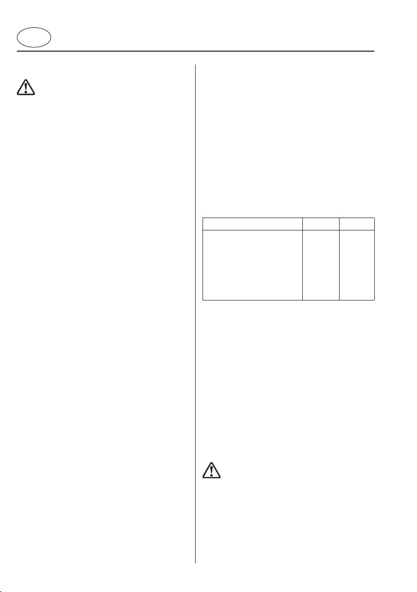
5.2 Wechsel des Netzkabels
Sollte das Netzkabel einmal beschädigt oder verschlissen
sein, kann es durch eine Elektrofachkraft gewechselt
werden (siehe Bild 6 + 7).
Vor Reparaturen am Motor ist der Netzstecker
zu ziehen.
MA II:
Es muss mindestens ein Kabel der Qualität H05 RN-F
verwendet werden.
MI 4:
Es muss mindestens ein Kabel der Qualität H05 RN-F verwendet werden. Wenn die Motorhaube wieder montiert
wird, muss der Ein-/Ausschalter in Position “I” stehen,
da sonst der Überstromauslöser aus seiner Befestigung
springt oder beschädigt wird.
6. Reparaturen
Reparaturen nur vom Hersteller oder autorisierten Vertragswerkstätten ausführen lassen. Nur Lutz-Ersatzteile
verwenden.
Page 6

6
D
* gegen Mehrpreis
** Säureschutz
Tabelle 1 - Motorvarianten Typ MA II
Typ Spannung Frequenz Leistung Schalldruck-
pegel
3)
Gewicht Bestell-Nr.
Ohne Usp
Bestell-Nr.
Mit Usp
MA II 3
220-230 V
1)
50 Hz 430-460 W 71 dB(A) 4,6 kg
0060-000 0060-008
100-120 V
50-60 Hz 395 W 71 dB(A) 4,6 kg
0060-044 0060-016
MA II 5
220-230 V
1)
50 Hz 540-575 W 70 dB(A) 5,4 kg
0060-001 0060-009
220-230 V
60 Hz 450-490 W 70 dB(A) 5,4 kg
0060-042 0060-043
100-120 V
50-60 Hz 510 W 70 dB(A) 5,4 kg
0060-045 0060-017
42 V
50 Hz 520 W 70 dB(A) 5,9 kg
* 0060-014
24 V
= 400 W 70 dB(A) 5,3 kg
* 0060-015
MA II 5 S**
220-230 V
50 Hz 540-575 W 70 dB(A) 6,2 kg
0060-091 –
100-120 V
2)
50-60 Hz 510 W 70 dB(A) 5,4 kg
0060-094 –
MA II 7
220-230 V
1)
50 Hz 750-795 W 69 dB(A) 6,6 kg
0060-002 0060-010
100-120 V
50-60 Hz 700 W 69 dB(A) 6,6 kg
0060-046 0060-018
1)
VDE-Zulassung
2)
Nicht funkentstört, daher nicht CE-konform
3)
bei 10000 1/min, Messabstand 1 m
Tabelle 2 - Motorvarianten Typ MI 4
Typ Spannung Frequenz Leistung Schall-
druckpegel
2)
Gewicht Bestell-Nr.
Ohne Dreh-
zahlsteller
Bestell-Nr.
Mit Dreh-
zahlsteller
MI 4-230
1)
220-230 V 50 Hz 450-500 W 70 dB(A) 2,8 kg
0030-000 -
MI 4-230 E
1)
220-230 V 50 Hz 450-500 W 70 dB(A) 2,8 kg
- 0030-001
MI 4-230
220-230 V
60 Hz 380-400 W 70 dB(A) 2,8 kg
0030-015 -
MI 4-230 E
220-230 V
60 Hz 380-400 W 70 dB(A) 2,8 kg
- 0030-016
MI 4-120
110-120 V
50-60 Hz 550-640 W 70 dB(A) 2,8 kg
0030-003 -
MI 4-120 E
110-120 V
50-60 Hz 550-640 W 70 dB(A) 2,8 kg
- 0030-006
MI 4-100 E
100 V
50-60 Hz 520-550 W 70 dB(A) 2,8 kg
- 0030-008
1)
VDE-Zulassung
2)
bei 10000 1/min, Messabstand 1 m
Page 7

7
GB
Table of Contents
1. General ............................................................................................................... 8
1.1 Scope of supply ........................................................................................... 8
2. Motor types ......................................................................................................... 8
2.1 Motor types MA II ........................................................................................ 8
2.2 Motor types MI 4 ......................................................................................... 8
2.3 Electrical design ........................................................................................... 8
3. Starting up .......................................................................................................... 8
3.1 Connection to the pump tube ....................................................................... 8
3.2 Electrical connection .................................................................................... 8
4. Operation ............................................................................................................ 9
4.1 Overcurrent release ...................................................................................... 9
4.2 Power failure and low voltage release (only MA II) ...................................... 9
4.3 Electronic speed controller (only MI 4-230 E, MI 4-120 E, MI 4-100 E)
....... 9
5. Maintenance ........................................................................................................ 9
5.1 Carbon brushes
............................................................................................ 9
5.2 Changing the power cable ............................................................................ 9
6. Repairs ................................................................................................................ 9
Declaration of Conformity MA II ..........................................................................
11
Declaration of Conformity MI 4 ...........................................................................
11
Page 8

8
General safety information
The operator must read and follow the operating
instructions before starting the motor.
1. The motor is not explosion proof. It is not allowed to
be operated in explosion hazard areas.
2. The motor must not be used to pump flammable
liquids.
3. The motor may only be operated in an upright
position.
4. The motor must not be immersed in the liquid being
pumped.
5. Ensure that all connections and fittings are properly
tightened.
6. The voltage specified on the rating plate must match
that provided by the mains/battery.
7. Ensure that the motor is switched off before connec
-
ting to the electricity supply.
8. Check the low voltage release if this is required for a
safe operation.
9. Do not operate motor without pump tube.
10. Do not stop the motor by using the speed controller.
Uncontrolled restart possible.
The national accident prevention regulations must be
observed without fail.
1. General
An electric drum and container pump comprises motor
and pump tube to suit the particular application. Motor
types MA II and MI 4 with the various pump tubes are
suitable for pumping non-flammable, aggressive, thinbodied liquids. Motors are not approved for use in or on
swimming pools, garden ponds, etc.
1.1 Scope of supply
Check that the consignment is complete as ordered.
2. Motor types
The pump motors are single-phase series-wound motors
with the operating voltages, input ratings and frequencies
specified according to table 1 and 2 (see page 10).
The input motor rating and the required voltage and
frequency are specified on the rating plate. Check that
the specified voltage and frequency match the available
mains supply.
Vibrations are transmitted to the operator as he holds the
motor in his hand during operation. The upper limbs are
exposed to an acceleration of less than 2.5 m/s².
2.3 Electrical design
Type
MA II MI 4
Double-pole on/off switch
Single-pole thermal
overcurrent release
Low voltage release Optional –
Protection class I
1)
II
Type of protection IP 54 IP 24
1)
Motors MA II 3-12, MA II 5-42 and MA II 5-24
correspond to protection class III.
3. Starting up
3.1 Connection to the pump tube
The motor is mounted on the pump tube. The upper
coupling on the motor engaging in the coupling of the
pump tube. The motor and pump tube are then firmly
connected by means of the handwheel (right-hand thread) (see Fig. 1).
3.2 Electrical connection (see Fig. 2)
The voltage specified on the rating plate must match that
provided by the mains/battery.
The on/off switch must be set to 0 before
connecting to the mains/battery.
DC motors can be connected in any required polarity to
the power supply.
GB
Page 9

9
GB
4. Operation
4.1 Overcurrent release
The overcurrent release integrated into the motor switches off the motor if overloaded. The on/off switch must
be actuated again in order to restart the motor after
allowing it to cool (see Fig. 3 + 4).
4.2 Power failure and low voltage release
(only MA II)
The on/off switch remains in position „I“ following a break in the power supply (disconnection
of the mains plug, power failure). The switch
must be set to „0“ in such cases in order to
avoid uncontrolled restarting of the motor.
Motors of type MA II are optionally equipped with a low
voltage release. Versions with low voltage release do
not start automatically again after interruption of power
supply (pull plug and plug-in again). The on/off switch
must be actuated again in order to restart the motor.
If the supply voltage drops considerably below the rated
value (mains supply with major voltage fluctuations), the
low voltage release may make it impossible to switch
on the motor.
Motors of type MI 4 are not equipped with a low voltage
release.
4.3 Electronic speed controller
(only MI 4-230 E, MI 4-120 E, MI 4-100 E)
The motors of type MI 4 are also available with an electronic speed controller with which the flow rate can be
reduced as required. The knob for the electronic speed
controller is located near the on/off switch. The direction
for higher and lower speed is indicated by the scale. The
flow rate at minimum speed depends on the respective
mains supply. At a free discharge it corresponds to approx. 40% of the maximum flow rate, but is less in all
other cases (see Fig. 5).
Do not stop the motor by using the speed controller when operating at 60 Hz frequency.
Uncontrolled restart possible.
5. Maintenance
5.1 Carbon brushes
Single-phase series-wound motors have a commutator
with two carbon brushes. Carbon brushes are subject
to wear. They must consequently be inspected by an
authorized repair shop or the manufacturer after approx.
500 hours of operation in order to prevent destruction
of the motor due to complete abrasion of the carbon
brushes.
5.2 Changing the power cable
If the power cable is damaged or worn, it can be replaced
by a qualified electrician (see Fig. 6 + 7).
The mains plug must always be disconnected
before repairing the motor in any way.
MA II:
The cable used must at least be of type H05 RN-F.
MI 4:
The cable used must at least be of type H05 RN-F. The
on/off switch must be set to „I“ when replacing the motor
cover, otherwise the overcurrent release will jump out of
position or be damaged.
6. Repairs
Repairs should only be made by the manufacturer or
authorized Lutz-dealers. Only use genuine Lutz spare
parts.
Page 10

10
* at extra charges
** acid proof coating
Table 1 - Motor type MA II
Type Voltage Frequency Power Sound
pressure
level
3)
Weight Order No.
Without
LVR
Order No.
With
LVR
MA II 3
220-230 V
1)
50 Hz 430-460 W 71 dB(A) 4.6 kg
0060-000 0060-008
100-120 V
50-60 Hz 395 W 71 dB(A) 4.6 kg
0060-044 0060-016
MA II 5
220-230 V
1)
50 Hz 540-575 W 70 dB(A) 5.4 kg
0060-001 0060-009
220-230 V
60 Hz 450-490 W 70 dB(A) 5.4 kg
0060-042 0060-043
100-120 V
50-60 Hz 510 W 70 dB(A) 5.4 kg
0060-045 0060-017
42 V
50 Hz 520 W 70 dB(A) 5.9 kg
* 0060-014
24 V
= 400 W 70 dB(A) 5.3 kg
* 0060-015
MA II 5 S**
220-230 V
50 Hz 540-575 W 70 dB(A) 6.2 kg
0060-091 –
100-120 V
2)
50-60 Hz 510 W 70 dB(A) 5.4 kg
0060-094 –
MA II 7
220-230 V
1)
50 Hz 750-795 W 69 dB(A) 6.6 kg
0060-002 0060-010
100-120 V
50-60 Hz 700 W 69 dB(A) 6.6 kg
0060-046 0060-018
1)
VDE-approval
2)
Not interference protected, therefore not CE-conformal
3)
At 10000 rpm, measured at a distance of 1 m.
Table 2 - Motor type MI 4
Type Voltage Frequency Power Sound
pressure
level
2)
Weight Order No.
Without
speed
controller
Order No.
With
speed
controller
MI 4-230
1)
220-230 V 50 Hz 450-500 W 70 dB(A) 2,8 kg
0030-000 –
MI 4-230 E
1)
220-230 V 50 Hz 450-500 W 70 dB(A) 2,8 kg
– 0030-001
MI 4-230
220-230 V
60 Hz 380-400 W 70 dB(A) 2,8 kg
0030-015 –
MI 4-230 E
220-230 V
60 Hz 380-400 W 70 dB(A) 2,8 kg
– 0030-016
MI 4-120
110-120 V
50-60 Hz 550-640 W 70 dB(A) 2,8 kg
0030-003 –
MI 4-120 E
110-120 V
50-60 Hz 550-640 W 70 dB(A) 2,8 kg
– 0030-006
MI 4-100 E
100 V
50-60 Hz 520-550 W 70 dB(A) 2,8 kg
– 0030-008
1)
VDE-approval
2)
At 10000 rpm, measured at a distance of 1 m.
GB
Page 11

EG-Konformitätserklärung
Hiermit erklären wir, dass die nachfolgend bezeichnete Maschine
aufgrund ihrer Konzipierung und Bauart sowie in der von uns in
Verkehr gebrachten Ausführung den einschlägigen grundlegenden
Sicherheits- und Gesundheitsanforderungen der aufgeführten EGRichtlinien entspricht.
Bei einer nicht mit uns abgestimmten Änderung der Maschine verliert
diese Erklärung ihre Gültigkeit.
Die Inbetriebnahme dieser Maschine ist so lange untersagt, bis festgestellt wurde, dass die vervollständigte Maschine (Pumpe) den Bestimmungen der EG-Maschinenrichtlinie und den angewandten Normen
entspricht. Bei Verwendung von Pumpwerken der Firma Lutz - Pumpen
GmbH erfüllt die vollständige Maschine die EG-Maschinenrichtlinie.
Geräteart: Motor zum Antrieb von Fass- und Behälterpumpen
Typen: MI 4-230 MI 4-120
MI 4-230 E MI 4-120 E
EG-Richtlinien:
EG-Maschinenrichtlinie (98/37/EG)
EG-Niederspannungsrichtlinie (73/23/EWG)
EG-Richtlinie über Elektromagnetische Verträglichkeit (2004/108/EG)
Angewandte harmonisierte Normen, insbesondere
EN ISO 12100-1 EN 55014-2 EN 60 555
EN ISO 12100-2 EN 60 335-1 EN 61000-3-2
EN 55014-1 EN 60 335-2-41 EN 61000-3-3
Angewandte nationale Normen und technische Spezifikationen,
insbesondere DIN 45635
Lutz - Pumpen GmbH
Erlenstraße 5-7 • D-97877 Wertheim
Declaration of Conformity
We herewith declare that the design and construction of the following machine in the versions marketed by us fully comply with the relevant basic
safety and health requirements specified by the EC Directives listed.
This declaration ceases to be valid if the machine is modified in any way
without prior consultation with us.
The machine may not be taken into service until it has been established
that the machine as a whole (pump) complies with the provisions of
the EC Directive on machinery safety and with the applicable standards.
The complete machine complies with the provisions of the EC Directive
on machinery safety when pump tubes made by Lutz-Pumpen GmbH
are used.
Type of device: Motor for driving drum and container pumps
Models: MI 4-230 MI 4-120
MI 4-230 E MI 4-120 E
EC Directives:
EC Directive on machinery safety (98/37/EC)
EC Directive of low voltage equipement (73/23/EEC)
EC Directive on electromagnetic compatibility (2004/108/EC)
Applicable harmonized standards, in particular:
EN ISO 12100-1 EN 55014-2 EN 60 555
EN ISO 12100-2 EN 60 335-1 EN 61000-3-2
EN 55014-1 EN 60 335-2-41 EN 61000-3-3
Applicable national standards and technical specifications, in particular: DIN 45635
EG-Konformitätserklärung
Hiermit erklären wir, dass die nachfolgend bezeichnete Maschine aufgrund ihrer Konzipierung und Bauart sowie in der von uns in Verkehr
gebrachten Ausführung den einschlägigen grundlegenden Sicherheitsund Gesundheitsanforderungen der aufgeführten EG-Richtlinien entspricht.
Bei einer nicht mit uns abgestimmten Änderung der Maschine verliert
diese Erklärung ihre Gültigkeit.
Die Inbetriebnahme dieser Maschine ist so lange untersagt, bis festgestellt wurde, dass die vervollständigte Maschine (Pumpe) den Bestimmungen der EG-Maschinenrichtlinie und den angewandten Normen
entspricht. Bei Verwendung von Pumpwerken der Firma Lutz - Pumpen
GmbH erfüllt die vollständige Maschine die EG-Maschinenrichtlinie.
Geräteart: Motor zum Antrieb von Fass- und Behälterpumpen
Typen: MA II 3-230 MA II 3-120 MA II 5-42
MA II 5-230 MA II 5-120
1)
MA II 5-24
MA II 7-230 MA II 7-120 MA II 3-12
1)
ausgenommen MA 5-120 S (Säureschutz)
EG-Richtlinien:
EG-Maschinenrichtlinie (98/37/EG)
EG-Niederspannungsrichtlinie (73/23/EWG)
EG-Richtlinie über Elektromagnetische Verträglichkeit (2004/108/EG)
Angewandte harmonisierte Normen, insbesondere
EN ISO 12100-1 EN ISO 12100-2 EN 55 014-1
EN 55 014-2 EN 61 000-3-2 EN 61 000-3-3
Angewandte nationale Normen und technische Spezifikationen, insbesondere DIN VDE 0700 Teil 1, DIN VDE 0700 Teil 236, DIN 45635
Declaration of Conformity
We herewith declare that the design and construction of the following machine in the versions marketed by us fully comply with the relevant basic
safety and health requirements specified by the EC Directives listed.
This declaration ceases to be valid if the machine is modified in any way
without prior consultation with us.
The machine may not be taken into service until it has been established
that the machine as a whole (pump) complies with the provisions of
the EC Directive on machinery safety and with the applicable standards.
The complete machine complies with the provisions of the EC Directive
on machinery safefy when pump tubes made by Lutz-Pumpen GmbH
are used.
Type of device: Motor for driving drum and container pumps
Models: MA II 3-230 MA II 3-120 MA II 5-42
MA II 5-230 MA II 5-120
1)
MA II 5-24
MA II 7-230 MA II 7-120 MA II 3-12
1)
except MA 5-120 S (acid proof coating)
EC Directives:
EC Directive on machinery safety (98/37/EC)
EC Directive of low voltage equipement (73/23/EEC)
EC Directive on electromagnetic compatibility (2004/108/EC)
Applicable harmonized standards, in particular:
EN ISO 12100-1 EN ISO 12100-2 EN 55 014-1
EN 55 014-2 EN 61 000-3-2 EN 61 000-3-3
Applicable national standards and technical specifications, in particular: DIN VDE 0700 Part 1, DIN VDE 0700 Part 236, DIN 45635
Wertheim, 29.01.2008
Jürgen Lutz, Geschäftsführer, Managing Director
Wertheim, 29.01.2008
Jürgen Lutz, Geschäftsführer, Managing Director
Page 12

12
D
Technische Änderungen vorbehalten. 03/08
Subject to technical changes. Best.-Nr. 0698-010 Printed in Germany Sch. 3.000/03.08
Lutz - Pumpen GmbH
Erlenstraße 5-7
D-97877 Wertheim
Tel. (0 93 42) 8 79-0
Fax (0 93 42) 87 94 04
e-mail: info@lutz-pumpen.de
http://www.lutz-pumpen.de
 Loading...