

Page 1
A Step-by-Step Guide for Installing, Operating and Maintaining a Lutron
AC Motor Group Controller
Please Read Before Installing
Models:
WC-2M-GC 2 Motor Controller
WC-4M-GC 4 Motor Controller
AC Motor Group Controller
Installer’s Guide
Page 2

2
Table of Contents
Description and Ratings . . . . . . . . . . . . . . . . . . . . . . .2
Important Information . . . . . . . . . . . . . . . . . . . . . . . . .2
System Diagram . . . . . . . . . . . . . . . . . . . . . . . . . . . . .3
Determine a Mounting Location . . . . . . . . . . . . . . . . .4
Pre-installation Motor Wiring Check . . . . . . . . . . . . . .5
Line Voltage Wiring . . . . . . . . . . . . . . . . . . . . . . . . . . .6
Configuring the Motor Direction for
Open and Close Functions . . . . . . . . . . . . . . . . . . . . .7
Contact Closure Input Control Wiring . . . . . . . . . . . .7
Example of Individual Control
(no dedicated stop input) . . . . . . . . . . . . . . . . . . .8
Example of individual Control
(with dedicated stop input) . . . . . . . . . . . . . . . . . .9
Example of Master Control
(with dedicated stop input) . . . . . . . . . . . . . . . . .10
Connecting Multiple Group Controllers . . . . . . .11
Setting the Contact Closure Input Type . . . . . . . . . .12
Appendix A . . . . . . . . . . . . . . . . . . . . . . . . . . . . . . . .13
Troubleshooting . . . . . . . . . . . . . . . . . . . . . . . . . . . .14
Important Information
• Before starting the installation, please completely read
these installation instructions.
• This control must be installed by a certified electrician.
• Install in accordance with all local and national electrical
codes.
• Turn power OFF at circuit breaker or remove fuse
before installing and wiring the controller. Do not wire
with power ON.
• Operating environment should be between 32° F to
104° F (0° C to 40° C).
• Proper short circuit protection and overload protection
must be provided at the distribution panel. You can use
up to a 20 A breaker for your application, where
applicable.
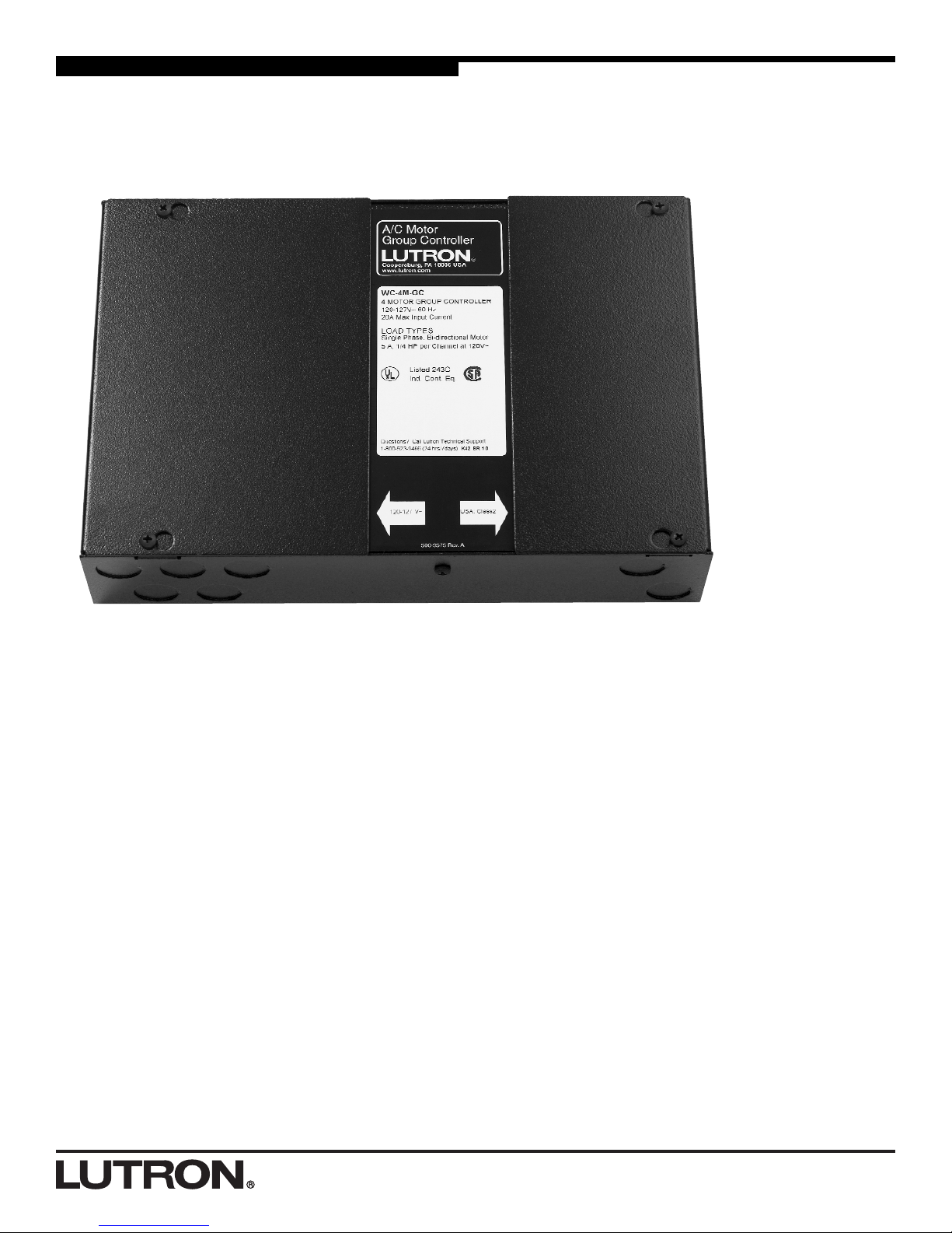
Description
The WC-2M-GC and WC-4M-GC Group Controllers are
designed to control AC motorized window treatments and
projection screens. Both control single phase, bi-directional
AC motors (three wire motors: open, close, neutral). Two
models are available to control up to two motors (WC-2MGC) or up to four motors (WC-4M-GC). Both accept inputs
from controls that provide low-voltage, Class 2, dry contact
closures. Each Group Controller has individual motor
control inputs as well as a master control input. This allows
individual control of each motor or control of all motors at
the same time.
Ratings
Input
110–127 V
~, 60 Hz Single Phase
20 A maximum input current
Load Capacity
5 A, 1/4 HP motor load per channel @ 120 V~
Page 3
3
12345
ON
COM1
CLOSE1
STOP1
OPEN1
OPEN1 CLOSE1 OPEN2 CLOSE2 OPEN3 CLOSE3 OPEN4 CLOSE4 OPEN ALL CLOSE ALL
MASTER CONTROLS
PROGRAM
STATUS
POWER
OPTIONS
MS 240V 120V N N C1 O1 N C2 O2 N C3 O3 N C4 O4
COM2
CLOSE2
STOP2
OPEN2
COM3
CLOSE3
STOP3
OPEN3
COM4
CLOSE4
STOP4
OPEN4
COM
CLOSE
STOP
OPEN
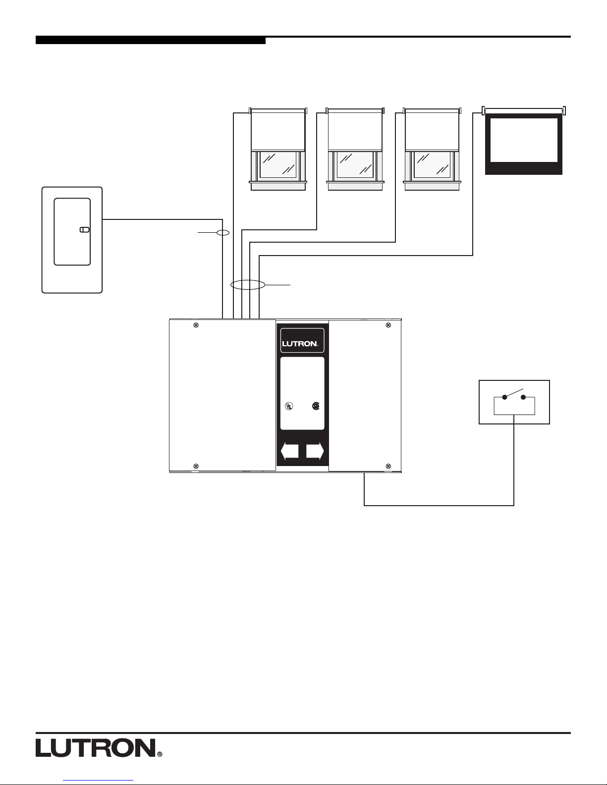
System Diagram
AC Motorized
Window
Treatment
WC-4M-GC Group Controller
Distribution Panel
Class 2/PELV Wiring
Line-Voltage 3 Wire AC Motor Wiring
3 conductors plus ground
Line-Voltage Wiring
AC Motor
Group Controller
Coopersburg, PA 18036 USA
www.lutron.com
®
WC-4M-GC
4 MOTOR GROUP CONTROLLER
110-127 V~ 60 Hz
20 A Max. Input Current
LOAD TYPES
Single Phase, Bi-directional Motor
5 A, 1/4 HP per Channel at 120 V~
TYPES DE CHARGES
Phase Simple, Moteur Bidirectionel
5 A, 1/4 HP par Canal a 120 V~
Listed 243C
Ind. Cont. Eq.
Questions? Call Lutron Technical Support
1-800-523-9466 (24 hrs/7 days)
110-127 V~ USA: Class 2
AC Motorized
Window
Treatment
AC Motorized
Window
Treatment
AC Motorized
Projection Screen
Contact Closure Device
(provided by others)
2 conductors
plus ground
Page 4
44
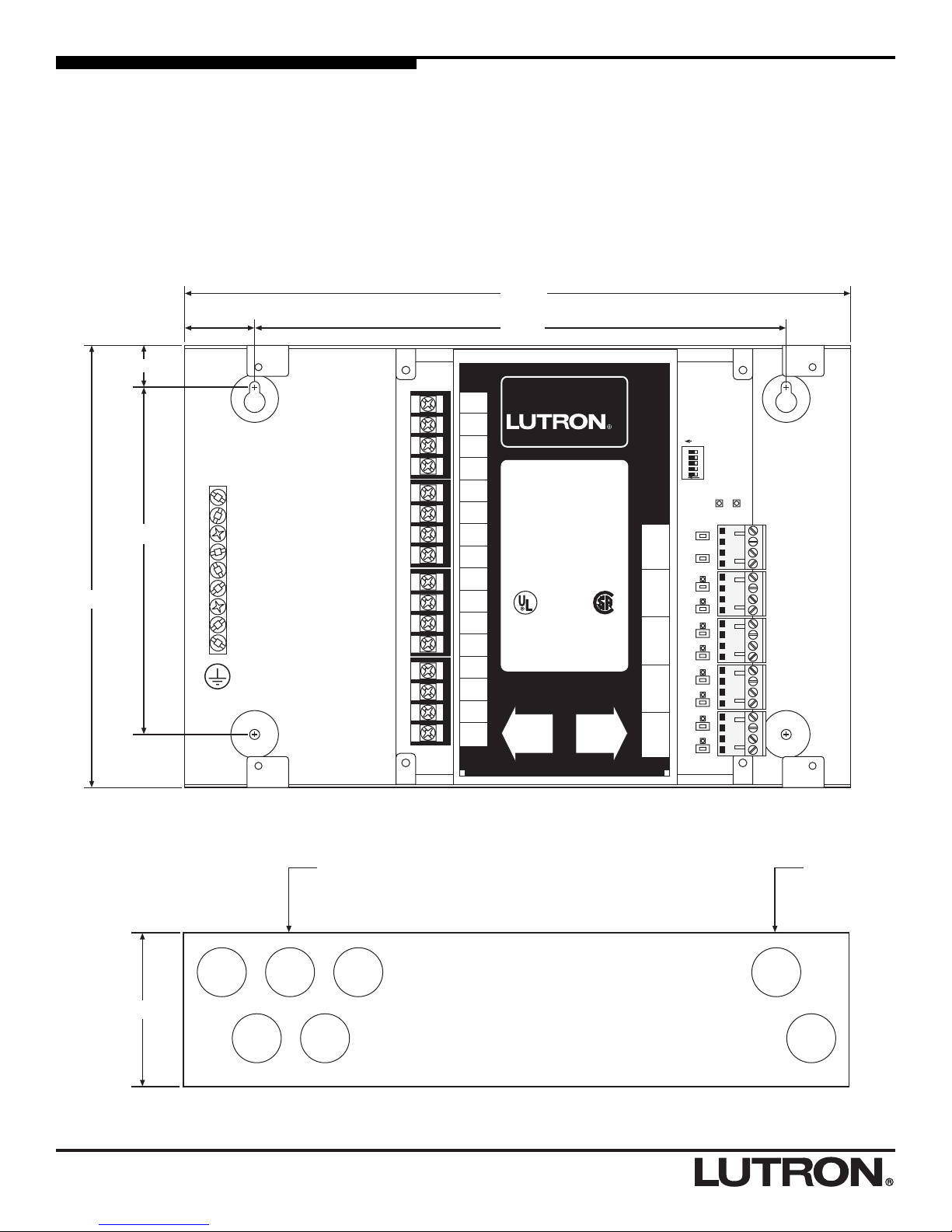
Determine a Mounting Location
• Mount the WC-2M-GC, WC-4M-GC on a dry, flat indoor
surface such as an electrical closet wall.
• Mount unit in a location that is accessible to allow for
system programming and setup.
• Unit may be mounted in any orientation.
• The unit’s relays will click audibly in normal use. Mount
in a location where this is acceptable.
• The keyholes accept a maximum of 3/16" (5 mm)
mounting bolt. No. 8 (M4) bolt recommended.
• Knockouts are 7/8" (22 mm) in diameter.
12345
ON
STATUS POWER
OPTIONS
Neutral
120V
240V
Motor
Supply
ON
OPEN 1
CLOSE 1
OPEN ALL
CLOSE ALL
OPEN 4
CLOSE 4
OPEN 3
CLOSE 3
OPEN 2
CLOSE 2
SW Live
1B
SW Live
1A
Neutral
SW Live
2B
SW Live
2A
Neutral
SW Live
3B
SW Live
3A
Neutral
SW Live
4B
SW Live
4A
Neutral
9.5 in.
12 in.
6.2 in.
1.25 in.
7.9 in.
.735 in.
AC Motor
Group Controller
Coopersburg, PA 18036 USA
www.lutron.com
500-9575 Rev. B
®
WC-4M-GC
4 MOTOR GROUP CONTROLLER
110-127 V~ 60 Hz
20 A Max. Input Current
LOAD TYPES
Single Phase, Bi-directional Motor
5 A, 1/4 HP per Channel at 120 V~
TYPES DE CHARGES
Phase Simple, Moteur Bidirectionel
5 A, 1/4 HP par Canal a 120 V~
Listed 243C
Ind. Cont. Eq.
Questions? Call Lutron Technical Support
1-800-523-9466 (24 hrs/7 days)
110-127 V~ USA: Class 2
COM
Open
Stop
Close
COM
Open4
Stop4
Close4
COM
Open3
Stop3
Close3
COM
Open2
Stop2
Close2
COM
Open1
Stop1
Close1
Neutral
120 V
Motor
Supply
Jumper
SW Live
4B
SW Live
4A
Neutral
SW Live
3B
SW Live
3A
Neutral
SW Live
2B
SW Live
2A
Neutral
SW Live
1B
SW Live
1A
Neutral
Line-voltage input power and
motor power wiring entry
Class 2/PELV
wiring entry
2.75 in.
Front View
Side View
Page 5
55
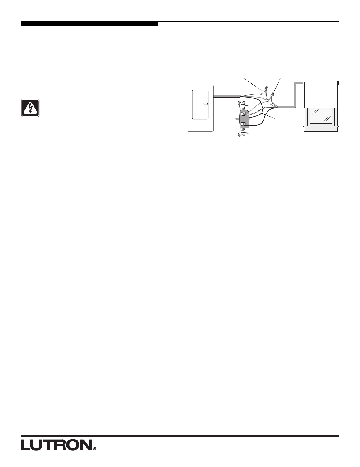
Distribution
Panel
Neutrals Earth/Grounds
Hot/Live
Danger - Locate and lock the supply breaker in
the OFF position or remove the supply fuse
before working on any circuit.
Momentary
SPDT Switch
(wallbox not
shown)
AC Motorized
Window
Treatment Shown
Pre-installation Motor Wiring Check
Test your wiring before connecting to the Group Controller.
Use either a momentary, Single Pole Double Throw
(SPDT) switch (as described below) or a motor wiring test
kit (available from Lutron). To order the motor wiring test
kit, contact Lutron at 1-888-SIVOIA1 (1-888-748-6481) and
ask for model 6020086.
Note: If using the motor wiring test kit, please refer to the
instructions provided with the kit.
Testing motor wiring using a SPDT switch:
1. Turn power OFF at circuit breaker (MCB) or remove
fuse.
2. Connect the motor ground wire to earth ground.
Connect earth ground to the ground terminal on the
switch.
3. Connect the motor neutral wire to supply neutral.
4. Using one momentary, Single Pole Double Throw
(SPDT) switch for each motor, connect hot/live to the
common terminal on the switch.
5. Connect one each of the motor power wires to the
output terminals on the switch. Never wire more than
one motor to a switch.
6. Mount switch in a wallbox. Be sure no bare wires or
terminals on the switch are exposed.
7. After verifying it is safe to restore power, turn power
ON.
8. Verify motor will raise/open and lower/close properly. If
necessary, remove power and correct wiring.
Page 6

66
Line-Voltage Wiring
Connect line voltage and the AC Motors to the Group
Controller.
12345
ON
STATUS POWER
OPTIONS
Neutral
120V
240V
Motor
Supply
ON
OPEN ALL
CLOSE ALL
OPEN 4
CLOSE 4
OPEN 3
CLOSE 3
OPEN 2
CLOSE 2
OPEN 1
CLOSE 1
SW Live
1B
SW Live
1A
Neutral
SW Live
2B
SW Live
2A
Neutral
SW Live
3B
SW Live
3A
Neutral
SW Live
4B
SW Live
4A
Neutral
WC-4M-GC Group Controller
AC Motor 1
Motor 4 Power Wires
Motor 3 Power Wires
Motor 2 Power Wires
Motor 1 Power Wires
Power Feed Wiring
Danger - Locate and lock the supply breaker in
the OFF position or remove the supply fuse
before working on any circuit.
• Only connect one motor to each output. Never wire
motors in parallel.
• The WC-2M-GC and WC-4M-GC accepts 110-127 V~,
60 Hz.
• Strip 1/2" of insulation from all power feed and motor
power wires.
• Run power to the Motor Supply Jumper terminal.
Connect the Motor Supply Jumper terminal to the
120 V Input Voltage terminal using a piece of wire of
the same gauge as the power feed wiring.
• Connect the motor power wires to the appropriate
terminals indicated in the diagram below.
• There is a dedicated earth/grounding block to land the
ground connections for the power feed and each motor.
The recommended tightening torque is 9.0 in-lbs for
line-voltage connections and 10 in-lbs for earth ground
connections.
• Run all power feed and motor power wiring through the
knockout holes on the sides of the unit.
Wiring Detail
Neutral
120V
240V
Motor
Supply
SW Live
1B
SW Live
1A
Neutral
SW Live
2A
Neutral
Power Feed Wiring
Motor 1 Power Wires
SW Live 1B
SW Live 1A
Neutral
Neutral
120 V Input
Motor Supply Jumper
Wiring Overview
Note: Motor power wire colors may
vary depending on the motor
manufacturer. Refer to the motor
manufacturer’s instructions for more
detailed wiring information.
Earth/Grounding
Block
AC Motor 2 AC Motor 3 AC Motor 4
Ground *
* Motor earth/ground wire is not shown in
this diagram. See Wiring Detail below.
Wiring entry knockouts
AC Motor
Group Controller
Coopersburg, PA 18036 USA
www.lutron.com
500-9575 Rev. B
®
WC-4M-GC
4 MOTOR GROUP CONTROLLER
110-127 V~ 60 Hz
20 A Max. Input Current
LOAD TYPES
Single Phase, Bi-directional Motor
5 A, 1/4 HP per Channel at 120 V~
TYPES DE CHARGES
Phase Simple, Moteur Bidirectionel
5 A, 1/4 HP par Canal a 120 V~
Listed 243C
Ind. Cont. Eq.
Questions? Call Lutron Technical Support
1-800-523-9466 (24 hrs/7 days)
110-127 V~ USA: Class 2
COM
Open
Stop
Close
COM
Open4
Stop4
Close4
COM
Open3
Stop3
Close3
COM
Open2
Stop2
Close2
COM
Open1
Stop1
Close1
Neutral
120 V
Motor
Supply
Jumper
SW Live
4B
SW Live
4A
Neutral
SW Live
3B
SW Live
3A
Neutral
SW Live
2B
SW Live
2A
Neutral
SW Live
1B
SW Live
1A
Neutral
Page 7

77
Contact Closure Input Control Wiring
The WC-2M-GC and WC-4M-GC accept Class 2, dry
contact closure inputs. The contact closure inputs for this
unit may be either momentary or maintained. The contact
closure type selected using the Options switch #5 (OFF =
Momentary, ON = Maintained). Momentary dry contact
closure inputs require a minimum closure time of 0.2
seconds.
The contact closure device must be able to switch 2 mA
at 30 Vdc. If multiple channels or Group Controllers are
wired in parallel to one contact closure, the contact
closure device must be rated for the total current of all the
channels or Group Controllers wired together (total
current = 2 mA times the number of Group Controllers or
channels in parallel). Example, if you connect 4 Group
Controllers in parallel, the contact closure device would
need to be rated for at least 8 mA, at 30 Vdc.
12345
ON
PROGRAM
STATUS POWER
OPTIONS
ON
OPEN ALL
CLOSE ALL
OPEN 4
CLOSE 4
OPEN 3
CLOSE 3
OPEN 2
CLOSE 2
OPEN 1
CLOSE 1
Operate the
channel using the
Open and Close
buttons
8036 USA
500-9575 Rev. B
®
CONTROLLER
Technical Support
USA: Class 2
COM
Open
Stop
Close
COM
Open4
Stop4
Close4
COM
Open3
Stop3
Close3
COM
Open2
Stop2
Close2
COM
Open1
Stop1
Close1
Change the
desired channel’s
output direction by
switching the
corresponding
Options switch
Configuring the Motor Direction for the
Open and Close Functions
For each Channel of the unit, the motor’s direction of
rotation needs to be configured for the Open and Close
functions so that the AC Motor will move in the proper
direction. This is accomplished using the Options
Switches, #1 through #4. This step needs to be performed
whether each channel is controlled individually or all
channels are controlled together.
1. Restore power to unit. Once the appropriate line
voltage and motor connections have been made to the
unit, replace the cover on the line voltage wiring
compartment. Remove the cover from the Class 2
wiring compartment. Turn power back ON.
2. Determine AC motor position. Determine whether
the AC Motor that is controlled by Channel 1 is open
or closed. If it is open, press the Close 1 manual
override button. If it is closed, press the Open 1
manual override button. If the AC Motor moves to the
desired position, the Channel is configured properly.
Proceed to Step 4. If the AC Motor does not move to
the desired position, proceed to Step 3.
3. Verify motor movement. If the AC Motor did not
move to the desired position in the prior step, slide the
Options Switch #1 to the opposite position. Press the
same button again that was pressed in Step 2 (Open
or Close). If the AC Motor moves to the desired
position Channel 1 is now configured properly.
Proceed to Step 4.
4. Repeat for remaining motors. Repeat Steps 2 and 3
for the rest of the Channels that are connected to AC
Motors. Options Switch #2 configures Channel 2,
Options Switch #3 configures Channel 3*, and Options
Switch #4 configures Channel 4*.
Each motor channel has a contact closure input terminal
block. In addition, the unit has a master control contact
closure input terminal block. The master control contact
closure input will operate all four motor channels
simultaneously. See the wiring diagrams on pages 10–11.
The stop function can be achieved either by providing a
contact closure input to the stop terminal of the input
terminal block, or by simultaneously providing a closure
on the open and close terminals of the input terminal
block. Both stop methods will be addressed in the wiring
diagrams on pages 8–11.
2
3
Note: Do not change the position of Options Switch #5.
This switch is used to change the contact closure input
type. See section Setting the Contact Closure Input Type
on page 12 for more details on the Options Switch #5.
* Channel 3 and 4 are only available on Group Controller model GRX-
4M-GC.
Page 8

88
WC-4M-GC Group Controller Shown
Class 2/PELV Wiring
Com 1
Open 1
Close 1
Com 2
Open 2
Close 2
Com 3
Open 3
Close 3
Com 4
Open 4
Close 4
Example of Individual Control (no dedicated stop
input)
In this wiring example, the stop function is achieved by
simultaneously providing a closure on the open and close
terminals of the input terminal block. No connection is
made to the stop terminal on the input terminal block.
Contact
closure inputs
3 and 4 are
only available
on the WC-
4M-GC
ler
SA
500-9575 Rev. B
®
120 V~
COM
Open
Stop
Close
COM
Open4
Stop4
Close4
COM
Open3
Stop3
Close3
COM
Open2
Stop2
Close2
COM
Open1
Stop1
Close1
ON
12345
ON
OPTIONS
OPEN ALL
CLOSE ALL
CLOSE 4
CLOSE 3
CLOSE 2
CLOSE 1
OPEN 4
OPEN 3
OPEN 2
OPEN 1
STATUS POWER
Page 9

99
Example of Individual Control (with dedicated stop
input)
In this wiring example, the stop function is achieved by
providing a closure to the stop terminal of the input
terminal block.
WC-4M-GC Group Controller Shown
Class 2/PELV Wiring
Com 1
Open 1
Stop 1
Close 1
Com 2
Open 2
Stop 2
Close 2
Com 3
Open 3
Stop 3
Close 3
Com 4
Open 4
Stop 4
Close 4
Contact
closure inputs
3 and 4 are
only available
on the WC-
4M-GC
ler
SA
500-9575 Rev. B
®
120 V~
COM
Open
Stop
Close
COM
Open4
Stop4
Close4
COM
Open3
Stop3
Close3
COM
Open2
Stop2
Close2
COM
Open1
Stop1
Close1
ON
12345
ON
OPTIONS
OPEN ALL
CLOSE ALL
CLOSE 4
CLOSE 3
CLOSE 2
CLOSE 1
OPEN 4
OPEN 3
OPEN 2
OPEN 1
STATUS POWER
Page 10

1010
Example of Master Control (with dedicated stop input)
In this wiring example, each master function is achieved
by providing a closure to the open, stop, or close terminal
of the input terminal block. Activating any closure will
affect all motors connected to this Group Controller.
12345
ON
STATUS POWER
OPTIONS
ON
OPEN ALL
CLOSE ALL
OPEN 4
CLOSE 4
OPEN 3
CLOSE 3
OPEN 2
CLOSE 2
OPEN 1
CLOSE 1
WC-4M-GC Group Controller Shown
Class 2/PELV Wiring
Com
Open All
Stop All
Close All
Input controls
channel 1
motor only
(optional)
Input controls
channel 2
motor only
(optional)
Input controls
channels 3
and 4 motors
only
(optional)*
Input simulta-
neously
controls all
four channels
* Contact closure inputs 3 and 4 are only available on the
WC-4M-GC
ler
SA
500-9575 Rev. B
®
120 V~
COM
Open
Stop
Close
COM
Open4
Stop4
Close4
COM
Open3
Stop3
Close3
COM
Open2
Stop2
Close2
COM
Open1
Stop1
Close1
Page 11

1111
Connecting Multiple Group Controllers
Multiple Group Controllers can be wired in parallel on the
Class 2/PELV side to obtain simultaneous control of
multiple shades. To do this, parallel wire the control wires
from the contact closure device to each Group Controller’s
contact closure input terminal block. See the diagram
below. This may be used for the individual inputs and/or
master control input.
12345
ON
STATUS POWER
OPTIONS
ON
OPEN ALL
CLOSE ALL
OPEN 4
CLOSE 4
OPEN 3
CLOSE 3
OPEN 2
CLOSE 2
OPEN 1
CLOSE 1
12345
ON
STATUS POWER
OPTIONS
ON
OPEN ALL
CLOSE ALL
OPEN 4
CLOSE 4
OPEN 3
CLOSE 3
OPEN 2
CLOSE 2
OPEN 1
CLOSE 1
WC-4M-GC Group Controller Shown
Class 2/PELV Wiring
To Additional Group
Controllers
WC-4M-GC Group Controller Shown
Input controls channels
1 and 2 motors on this
unit only
Input simultaneously
controls all four
channels on all units
parallel wired together
Note: When connecting multiple Group Controllers in
parallel, make sure the contact closure device is rated for
the total amount of current delivered by each Group
Controller (total current = 2 mA times the number of Group
Controllers). Example, if you connect 4 Group Controllers
in parallel, the contact closure switch would need to be
rated for at least 8 mA, at 30 Vdc.
ller
500-9575 Rev. B
®
ROLLER
t 120 V~
irectionel
cal Support
Class 2
COM
Open
Stop
Close
COM
Open4
Stop4
Close4
COM
Open3
Stop3
Close3
COM
Open2
Stop2
Close2
COM
Open1
Stop1
Close1
ller
500-9575 Rev. B
®
ROLLER
t 120 V~
irectionel
cal Support
Class 2
COM
Open
Stop
Close
COM
Open4
Stop4
Close4
COM
Open3
Stop3
Close3
COM
Open2
Stop2
Close2
COM
Open1
Stop1
Close1
Page 12

1212
Setting the Contact Closure Input Type
When operating from contact closure inputs, the WC-2MGC and WC-4M-GC can accept either momentary or
maintained contact closure inputs. See Appendix A on
page 13 for a more detailed description
Momentary Inputs: The unit will accept a momentary
closure input of greater than 0.2 seconds to activate the
desired function, i.e. raise, lower, or stop. The power
relays will open 2 minutes after either the open or close
contact closure is received, or when another contact
closure is received, whichever comes first. The relays will
open immediately upon receiving the stop contact
closure.
Maintained Inputs: The power relays remain closed as
long as the input closure remains closed. However, the
most recent command received will be executed even if
the previous contact closure is still maintained.
Momentary or maintained inputs are selected using
Options switch #5. In the ON position, maintained mode
is selected. In the OFF position, momentary operation is
selected.
ON =
Maintained Inputs
Options DIP Switch
Options DIP Switch
OFF =
Momentary Inputs
ON
12345
ON
12345
Page 13

13
Contact Closure Inputs:
Maintained Mode Operation
In maintained mode, the Switched Live output for a
channel, for instance SW Live 1A, is energized only while
the contact closure is provided to the input for that
channel. As soon as the contact closure is removed from
the input, the Switched Live output is de-energized. This
gives rise to possible conflicts if a contact closure is
provided during the time another contact closure is
provided. Below are descriptions of how the Group
Controller addresses these situations.
Inputs on a single channel
When a contact closure is provided to a single input on an
individual channel, the Group Controller will energize the
appropriate Switched Live output. If a contact closure is
then provided to another input on that same channel while
the first contact closure is provided, the Group Controller
will recognize this combination as a request to stop. This
will happen regardless of how much time elapses between
the application of the two contact closure inputs.
For example, if a contact closure is provided to Close 1,
the Group Controller will energize the Switched Live
output to close the AC motor on Channel 1. If a contact
closure is provided to Open 1 while a contact closure is
still provided to Close 1, the Group Controller will deenergize the Switched Live output on Channel 1, stopping
the AC motor.
If contact closures are provided to both the Open and
Close inputs on a particular channel, the Group Controller
will de-energize the Switched Live outputs for that
channel. If one of the contact closures is then released,
the Group Controller will NOT recognize that as a request
to move the AC motor to the position indicated by the
contact closure that is still provided. Instead, the Group
Controller will leave the Switched Live outputs deenergized. In order for the Group Controller to recognize a
new input signal, the contact closure must be removed
and then provided again.
Note: It is not recommended to connect two or more
contact closure devices on the same channel if
Momentary mode is selected. If this is done, it is possible
for a channel to become unresponsive to inputs if contact
closures are provided by the two devices at the same
time.
For instance, if one device provides a contact closure to
the Open input, the Group Controller energizes the
Switched Live output that opens the AC motor. If the
second device then provides a contact closure to the
Close input, the Group Controller will then de-energize the
Switched Live output, stopping the AC motor. At this point,
both contact closures must be removed before the Group
Controller will recognize a new request.
If it is desired to connect two or more contact closure
devices on the same channel, use Maintained mode.
Inputs on a single channel and Master Control
When a contact closure is provided to a single input on an
individual channel, the Group Controller will energize the
appropriate Switched Live output. If a contact closure is
then provided to a Master Control input while the first
contact closure is still provided, the Group Controller will
energize the Switched Live outputs requested by the
Master function on all channels of the Group Controller.
For example, if a contact closure is provided to Close 1,
the Group Controller will energize the Switched Live
output to close the AC motor on Channel 1. If a contact
closure is then provided to the Master Open input while a
contact closure is still provided to the Close 1 input, the
Group Controller will energize the Switched Live outputs
to open the AC motor on all channels.
When a contact closure is provided to a Master Control
input, the Group Controller will energize the appropriate
Switched Live outputs on all channels of the Group
Controller. If a contact closure is then provided to a single
input on an individual channel while the Master Control
contact closure is still provided, the Group Controller will
activate the Switched Live output requested by the
individual input, while keeping the Switched Live output in
the same state for the other three channels.
For example if a contact closure is provided to the Master
Open input, the Group Controller will energize the
Switched Live outputs to open the AC motor on all
channels. If a contact closure is then provided to the
Close 1 input, the Group Controller will energize the
Switched Live output on Channel 1 to close the AC motor
on Channel 1, but continue energizing the Switched Live
outputs on Channels 2, 3 and 4
Appendix A
Page 14

14
AC motor does not move in either
direction when manual override
buttons pressed.
• Motor wired to Group Controller
improperly.
• Limit switches on motor not set
properly.
• Motor Supply Jumper terminal is not
jumpered to 120 V terminal.
Verify motor wiring.
Verify limit switch settings on motor.
Place a jumper wire of sufficient wire
gauge between Motor Supply Jumper
and 120 V Input Voltage terminals.
See page 6.
Troubleshooting
Motors cannot be controlled from lowvoltage contact closure inputs but
operate properly with the manual
Open/Close buttons.
• Contact closure miswire. Verify connections on contact closure
inputs.
Motors only move while low-voltage
contact closure is applied.
• Options Switch #5 in ON position. Change position of Options Switch #5
to OFF. See page 11.
Motor moves in the wrong direction. • Options Switch not set properly. Reverse the corresponding Options
Switch. See page 7.
Symptom Possible Cause Solution
Page 15

15
Notes
Page 16

Lutron Electronics Co., Inc.
7200 Suter Road
Coopersburg, PA 18036-1299 U.S.A.
Made and printed in U.S.A. 12/02 P/N 031-216 Rev. A
Worldwide Technical and Sales
Assistance
If you have questions concerning the installation or operation of
this product, call the Lutron Technical Support Center. Please
provide exact model number when calling.
(800) 523-9466 (U.S.A., Canada, and the Caribbean)
Other countries call (610) 282-3800
Fax (610) 282-3090
Visit our web site at www.lutron.com
LIMITED WARRANTY
Lutron will, at its option, repair or replace any unit that is defective in materials or manufacture
within one year after purchase. For warranty service, return unit to place of purchase or mail to
Lutron at 7200 Suter Rd., Coopersburg, PA 18036-1299, postage pre-paid.
THIS WARRANTY IS IN LIEU OF ALL OTHER EXPRESS WARRANTIES, AND THE IMPLIED
WARRANTY OF MERCHANTABILITY IS LIMITED TO ONE YEAR FROM PURCHASE. THIS
WARRANTY DOES NOT COVER THE COST OF INSTALLATION, REMOVAL OR
REINSTALLATION, OR DAMAGE RESULTING FROM MISUSE, ABUSE, OR IMPROPER OR
INCORRECT REPAIR, OR DAMAGE FROM IMPROPER WIRING OR INSTALLATION. THIS
WARRANTY DOES NOT COVER INCIDENTAL OR CONSEQUENTIAL DAMAGES. LUTRON’S
LIABILITY ON ANY CLAIM FOR DAMAGES ARISING OUT OF OR IN CONNECTION WITH
THE MANUFACTURE, SALE, INSTALLATION, DELIVERY, OR USE OF THE UNIT SHALL
NEVER EXCEED THE PURCHASE PRICE OF THE UNIT.
This warranty gives you specific legal rights, and you may also have other rights which vary from
state to state. Some states do not allow limitations on how long an implied warranty lasts, so the
above limitation may not apply to you. Some states do not allow the exclusion or limitation of
incidental or consequential damages, so the above limitation or exclusion may not apply to you.
Lutron is a registered trademark and RadioTouch is a trademark of Lutron Electronics Co., Inc. ©
2002 Lutron Electronics Co., Inc.
 Loading...