

A Step-by-Step Guide for Installing, Operating and Maintaining a Lutron
AC Motor Group Controller
Please Read Before Installing
Models:
WC-2M-GC 2 Motor Controller
WC-4M-GC 4 Motor Controller
AC Motor Group Controller
Installer’s Guide

2
Table of Contents
Description and Ratings . . . . . . . . . . . . . . . . . . . . . . .2
Important Information . . . . . . . . . . . . . . . . . . . . . . . . .2
System Diagram . . . . . . . . . . . . . . . . . . . . . . . . . . . . .3
Determine a Mounting Location . . . . . . . . . . . . . . . . .4
Pre-installation Motor Wiring Check . . . . . . . . . . . . . .5
Line Voltage Wiring . . . . . . . . . . . . . . . . . . . . . . . . . . .6
Configuring the Motor Direction for
Open and Close Functions . . . . . . . . . . . . . . . . . . . . .7
Contact Closure Input Control Wiring . . . . . . . . . . . .7
Example of Individual Control
(no dedicated stop input) . . . . . . . . . . . . . . . . . . .8
Example of individual Control
(with dedicated stop input) . . . . . . . . . . . . . . . . . .9
Example of Master Control
(with dedicated stop input) . . . . . . . . . . . . . . . . .10
Connecting Multiple Group Controllers . . . . . . .11
Setting the Contact Closure Input Type . . . . . . . . . .12
Appendix A . . . . . . . . . . . . . . . . . . . . . . . . . . . . . . . .13
Troubleshooting . . . . . . . . . . . . . . . . . . . . . . . . . . . .14
Important Information
• Before starting the installation, please completely read
these installation instructions.
• This control must be installed by a certified electrician.
• Install in accordance with all local and national electrical
codes.
• Turn power OFF at circuit breaker or remove fuse
before installing and wiring the controller. Do not wire
with power ON.
• Operating environment should be between 32° F to
104° F (0° C to 40° C).
• Proper short circuit protection and overload protection
must be provided at the distribution panel. You can use
up to a 20 A breaker for your application, where
applicable.
Description
The WC-2M-GC and WC-4M-GC Group Controllers are
designed to control AC motorized window treatments and
projection screens. Both control single phase, bi-directional
AC motors (three wire motors: open, close, neutral). Two
models are available to control up to two motors (WC-2MGC) or up to four motors (WC-4M-GC). Both accept inputs
from controls that provide low-voltage, Class 2, dry contact
closures. Each Group Controller has individual motor
control inputs as well as a master control input. This allows
individual control of each motor or control of all motors at
the same time.
Ratings
Input
110–127 V
~, 60 Hz Single Phase
20 A maximum input current
Load Capacity
5 A, 1/4 HP motor load per channel @ 120 V~
3
12345
ON
COM1
CLOSE1
STOP1
OPEN1
OPEN1 CLOSE1 OPEN2 CLOSE2 OPEN3 CLOSE3 OPEN4 CLOSE4 OPEN ALL CLOSE ALL
MASTER CONTROLS
PROGRAM
STATUS
POWER
OPTIONS
MS 240V 120V N N C1 O1 N C2 O2 N C3 O3 N C4 O4
COM2
CLOSE2
STOP2
OPEN2
COM3
CLOSE3
STOP3
OPEN3
COM4
CLOSE4
STOP4
OPEN4
COM
CLOSE
STOP
OPEN
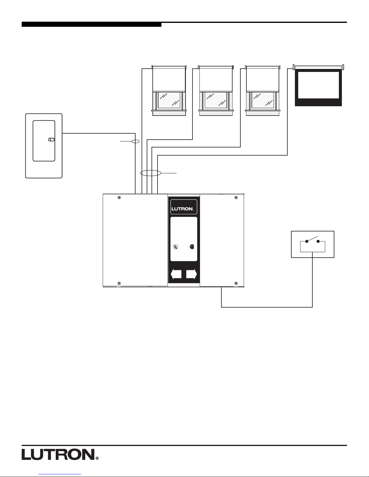
System Diagram
AC Motorized
Window
Treatment
WC-4M-GC Group Controller
Distribution Panel
Class 2/PELV Wiring
Line-Voltage 3 Wire AC Motor Wiring
3 conductors plus ground
Line-Voltage Wiring
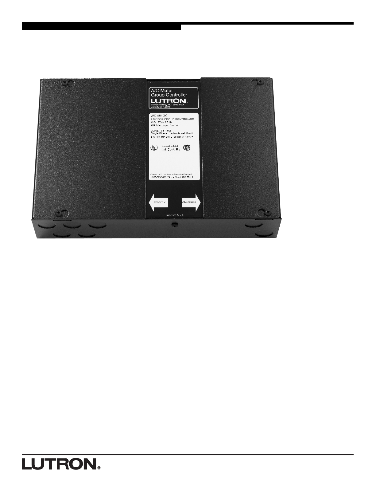
AC Motor
Group Controller
Coopersburg, PA 18036 USA
www.lutron.com
®
WC-4M-GC
4 MOTOR GROUP CONTROLLER
110-127 V~ 60 Hz
20 A Max. Input Current
LOAD TYPES
Single Phase, Bi-directional Motor
5 A, 1/4 HP per Channel at 120 V~
TYPES DE CHARGES
Phase Simple, Moteur Bidirectionel
5 A, 1/4 HP par Canal a 120 V~
Listed 243C
Ind. Cont. Eq.
Questions? Call Lutron Technical Support
1-800-523-9466 (24 hrs/7 days)
110-127 V~ USA: Class 2
AC Motorized
Window
Treatment
AC Motorized
Window
Treatment
AC Motorized
Projection Screen
Contact Closure Device
(provided by others)
2 conductors
plus ground
44
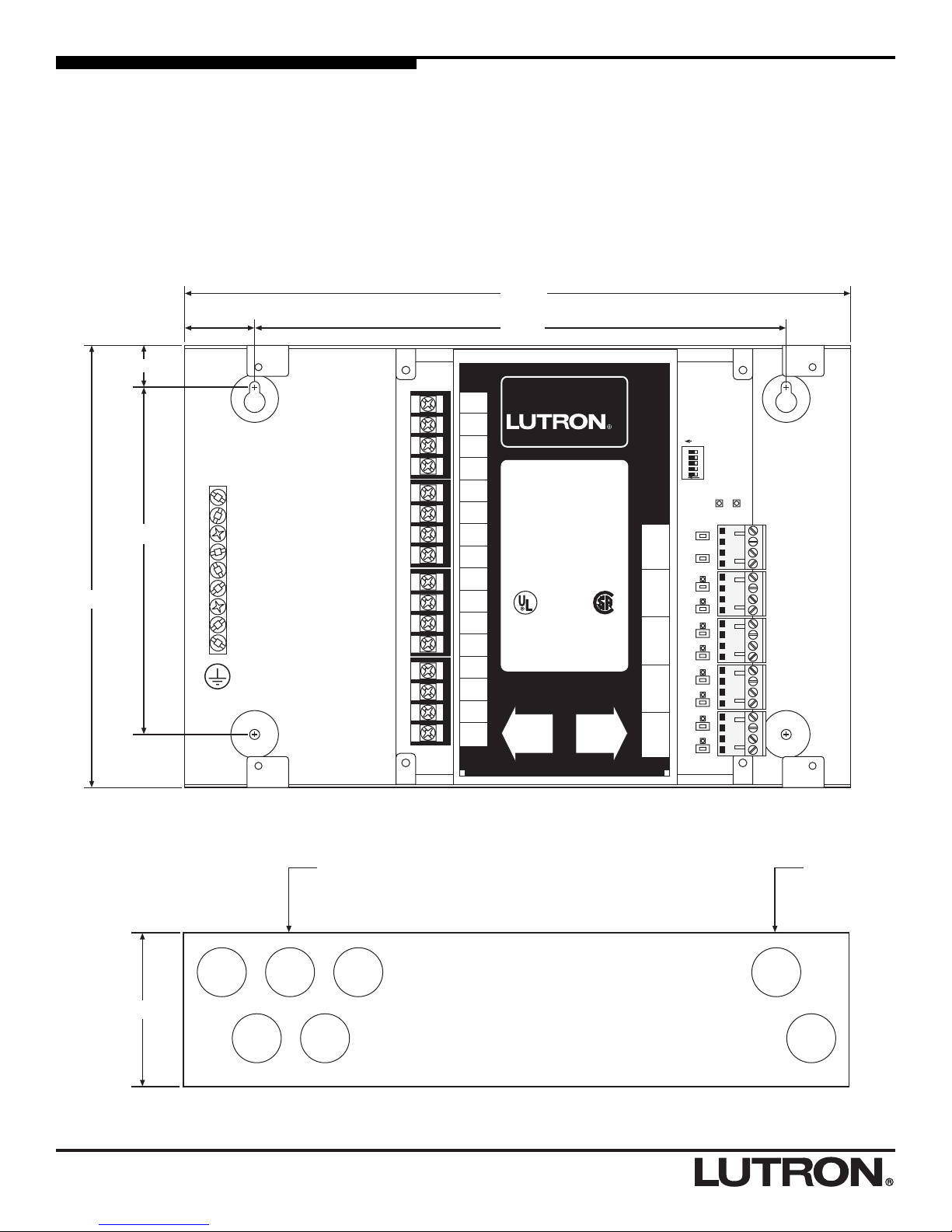
Determine a Mounting Location
• Mount the WC-2M-GC, WC-4M-GC on a dry, flat indoor
surface such as an electrical closet wall.
• Mount unit in a location that is accessible to allow for
system programming and setup.
• Unit may be mounted in any orientation.
• The unit’s relays will click audibly in normal use. Mount
in a location where this is acceptable.
• The keyholes accept a maximum of 3/16" (5 mm)
mounting bolt. No. 8 (M4) bolt recommended.
• Knockouts are 7/8" (22 mm) in diameter.
12345
ON
STATUS POWER
OPTIONS
Neutral
120V
240V
Motor
Supply
ON
OPEN 1
CLOSE 1
OPEN ALL
CLOSE ALL
OPEN 4
CLOSE 4
OPEN 3
CLOSE 3
OPEN 2
CLOSE 2
SW Live
1B
SW Live
1A
Neutral
SW Live
2B
SW Live
2A
Neutral
SW Live
3B
SW Live
3A
Neutral
SW Live
4B
SW Live
4A
Neutral
9.5 in.
12 in.
6.2 in.
1.25 in.
7.9 in.
.735 in.
AC Motor
Group Controller
Coopersburg, PA 18036 USA
www.lutron.com
500-9575 Rev. B
®
WC-4M-GC
4 MOTOR GROUP CONTROLLER
110-127 V~ 60 Hz
20 A Max. Input Current
LOAD TYPES
Single Phase, Bi-directional Motor
5 A, 1/4 HP per Channel at 120 V~
TYPES DE CHARGES
Phase Simple, Moteur Bidirectionel
5 A, 1/4 HP par Canal a 120 V~
Listed 243C
Ind. Cont. Eq.
Questions? Call Lutron Technical Support
1-800-523-9466 (24 hrs/7 days)
110-127 V~ USA: Class 2
COM
Open
Stop
Close
COM
Open4
Stop4
Close4
COM
Open3
Stop3
Close3
COM
Open2
Stop2
Close2
COM
Open1
Stop1
Close1
Neutral
120 V
Motor
Supply
Jumper
SW Live
4B
SW Live
4A
Neutral
SW Live
3B
SW Live
3A
Neutral
SW Live
2B
SW Live
2A
Neutral
SW Live
1B
SW Live
1A
Neutral
Line-voltage input power and
motor power wiring entry
Class 2/PELV
wiring entry
2.75 in.
Front View
Side View
55
Distribution
Panel
Neutrals Earth/Grounds
Hot/Live
Danger - Locate and lock the supply breaker in
the OFF position or remove the supply fuse
before working on any circuit.
Momentary
SPDT Switch
(wallbox not
shown)
AC Motorized
Window
Treatment Shown
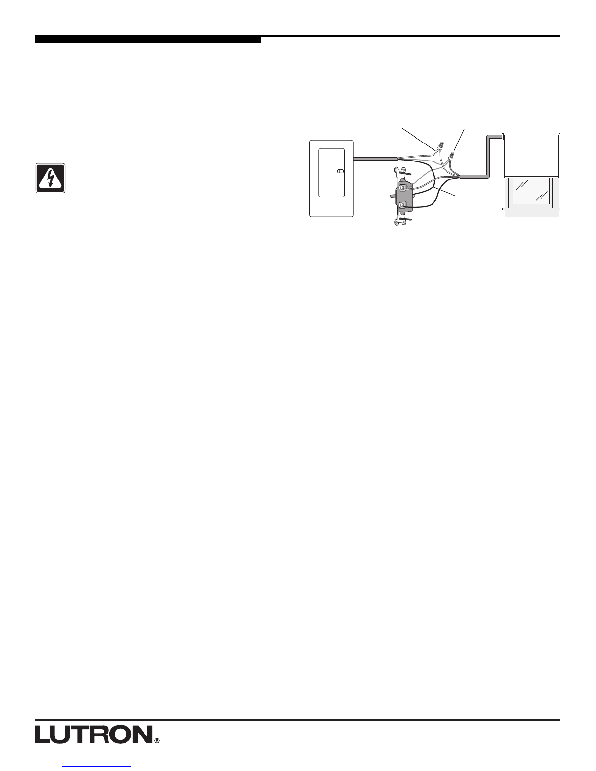
Pre-installation Motor Wiring Check
Test your wiring before connecting to the Group Controller.
Use either a momentary, Single Pole Double Throw
(SPDT) switch (as described below) or a motor wiring test
kit (available from Lutron). To order the motor wiring test
kit, contact Lutron at 1-888-SIVOIA1 (1-888-748-6481) and
ask for model 6020086.
Note: If using the motor wiring test kit, please refer to the
instructions provided with the kit.
Testing motor wiring using a SPDT switch:
1. Turn power OFF at circuit breaker (MCB) or remove
fuse.
2. Connect the motor ground wire to earth ground.
Connect earth ground to the ground terminal on the
switch.
3. Connect the motor neutral wire to supply neutral.
4. Using one momentary, Single Pole Double Throw
(SPDT) switch for each motor, connect hot/live to the
common terminal on the switch.
5. Connect one each of the motor power wires to the
output terminals on the switch. Never wire more than
one motor to a switch.
6. Mount switch in a wallbox. Be sure no bare wires or
terminals on the switch are exposed.
7. After verifying it is safe to restore power, turn power
ON.
8. Verify motor will raise/open and lower/close properly. If
necessary, remove power and correct wiring.
 Loading...