

Page 1
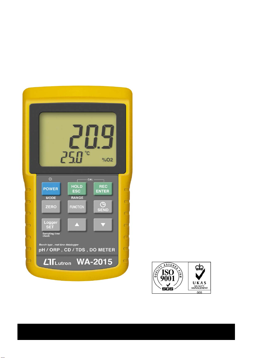
Bench type, RS232/USB computer interface
R
g
g
g
pH, ORP, CD, TDS, DO, SALT
METER
Model : WA-2015
Your purchase of this
pH, ORP, CD, TDS, DO,
SALT METER with SD
CARD DATALOGGE
marks a step forward for
you into the field of
precision measurement.
Althou
a complex and delicate
instrument, its durable
structure will allow
many years of use if
proper operatin
techniques are
developed. Please read
the followin
instructions carefully
and always keep this
manual within easy
reach.
h this METER is
OPERATION MANUAL
Page 2

TABLE OF CONTENTS
.
.
.
.
.
.
.
.
.
1. FEATURES................................................................1
2. SPECIFICATIONS......................................................3
2-1 General Specifications..........................................3
2-2 Electrical Specifications........................................5
3. FRONT PANEL DESCRIPTION....................................
4. MODE SELECTION ( pH/CD/DO selection ).................
5. pH/mV MEASURING and CALIBRATION
PROCEDURE............................................................
6. CONDUCTIVITY/TDS MEASURING and
CALIBRATION PROCEDURE.......................................19
7. DO (Dissolved Oxygen) MEASURING
and CALIBRATION PROCEDURE................................
8. DATA HOLD, DATA RECORD, DATA LOGGER
LCD BACKLIGHT ON/OFF..........................................31
9. ADVANCED ADJUSTMENT PROCEDURE......................34
9-1 Check memory space..........................................
9-2 Clear Memory.....................................................
9-3 Set Date/Time ....................................................36
9-4 Set sampling time ..............................................
9-5 Auto power OFF management..............................37
9-6 Select the Temp. unit to or ..........................℃℉ 37
9-7 Set pH manual Temp. compensation value............38
9-8 Set DO salt% compensation value........................38
9-9 Set DO height ( meter ) compensation value.........39
9-10 Set DO height ( feet ) compensation value..........39
9-11 Set CD temperature compensation factor............40
9-12 ESC.................................................................. 40
10. SEND THE DATA OUT FROM THE METER.................
11. RS232 PC SERIAL INTERFACE.................................
12. BATTERY REPLACEMENT.........................................45
13. SYSTEM RESET.......................................................45
14. OPTIONAL ACCESSORIES........................................46
9
11
12
24
35
35
36
41
43
Page 3

1. FEATURES
* Professional bench type meter with large size
LCD display with green color back light.
* One meter for multi purpose operation :
pH/ORP, CD/TDS ( Total dissolved solids ),
Dissolved Oxygen.
* pH : 0 to 14.00 pH, ORP : ± 1999 mV.
* Conductivity : 200 uS/2 mS/20 mS/200 mS.
* Dissolved oxygen : 0 to 20.0 mg/L.
* Real time data logger ( record year, month, date,
hour, minute, second ), 16,000 data logger.
* Auto data record, 16,000 Data logger no.
* Wide sampling time adjustment range from one
second to 8 hours 59 minutes 59 seconds.
* Auto data logger, manual data logger.
* RS232 computer interface.
* Max., Min., Data hold.
* Can default auto power off or manual power off.
* Optional pH, ORP, CD/TDS, Dissolved Oxygen and
ATC probe.
* DC 1.5V ( UM-3, AA ) x 8 PCs or DC 9V adapter in.
* pH meter function can select pH or ORP.
* pH measurement can select ATC or manual temperature
adjustment.
* pH measurement can make the auto calibration for
pH 7, pH 4 and pH 10 or other value.
* Conductivity measurement can select uS/mS or TDS
* Conductivity measurement can select Temp. Coefficient
of measurement solution.
* ATC for the conductivity measurement.
1
Page 4

* Dissolved oxygen meter use the polar graphic type
oxygen probe with temperature sensor, high precision
measurement for Dissolved Oxygen ( DO ) and
temperature measurement.
* Heavy duty dissolved oxygen probe, probe head can
connect with BOD bottle.
* DO use the automatic Temp. compensation.
* DO meter build in " % SALT " & " Mountain Height "
compensation value adjustment.
* Super large LCD display with LCD backlight ON/OFF.
* Separate probe, easy for operation of different
measurement environment.
* Wide applications: water conditioning, aquariums,
beverage, fish hatcheries, food processing,
photography, laboratory, paper industry, plating
industry, quality control, school & college, water
conditioning.
2
Page 5
2. SPECIFICATIONS
@
@
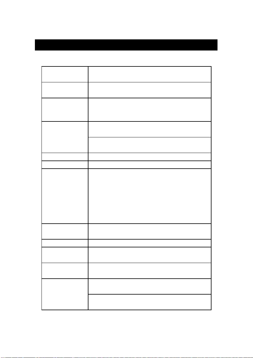
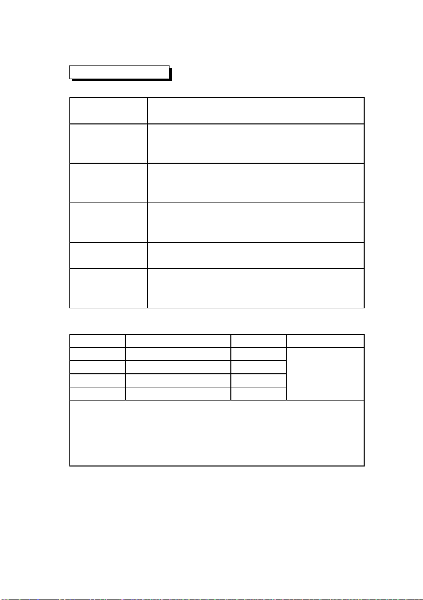
2-1 General Specifications
Circuit Custom one-chip of microprocessor LSI
circuit.
Display LCD size : 82 mm x 61 mm.
* with green color backlight.
Measurement pH/ORP
Conductivity/TDS(Total Dissolved Solids)
Dissolved Oxygen
Sampling Time
of Data Logger 1 sec to 8 hour 59 min. 59 sec.
Data Hold Freeze the display reading.
Memory Recall Maximum & Minimum value.
Power off Auto shut off saves battery life or
Sampling Time Approx. 1 second.
of display
Data Output RS 232 PC serial interface.
Operating 0 to 50 . - Main instrument.℃
Temperature
Operating Less than 80% R.H.
Humidity
Power Supply DC 1.5 V battery ( UM3 ) x 8 PCs,
Auto data logger :
Manual data logger :
Set sampling time to 0 second.
manual off by push Button.
Can default auto power or manual
power off.
When default auto power function,
power will off automatically after
10 MIN, if no Button be pressed.
( Heavy duty type ).
DC 9V adapter input.
@ AC/DC power adapter is optional.
3
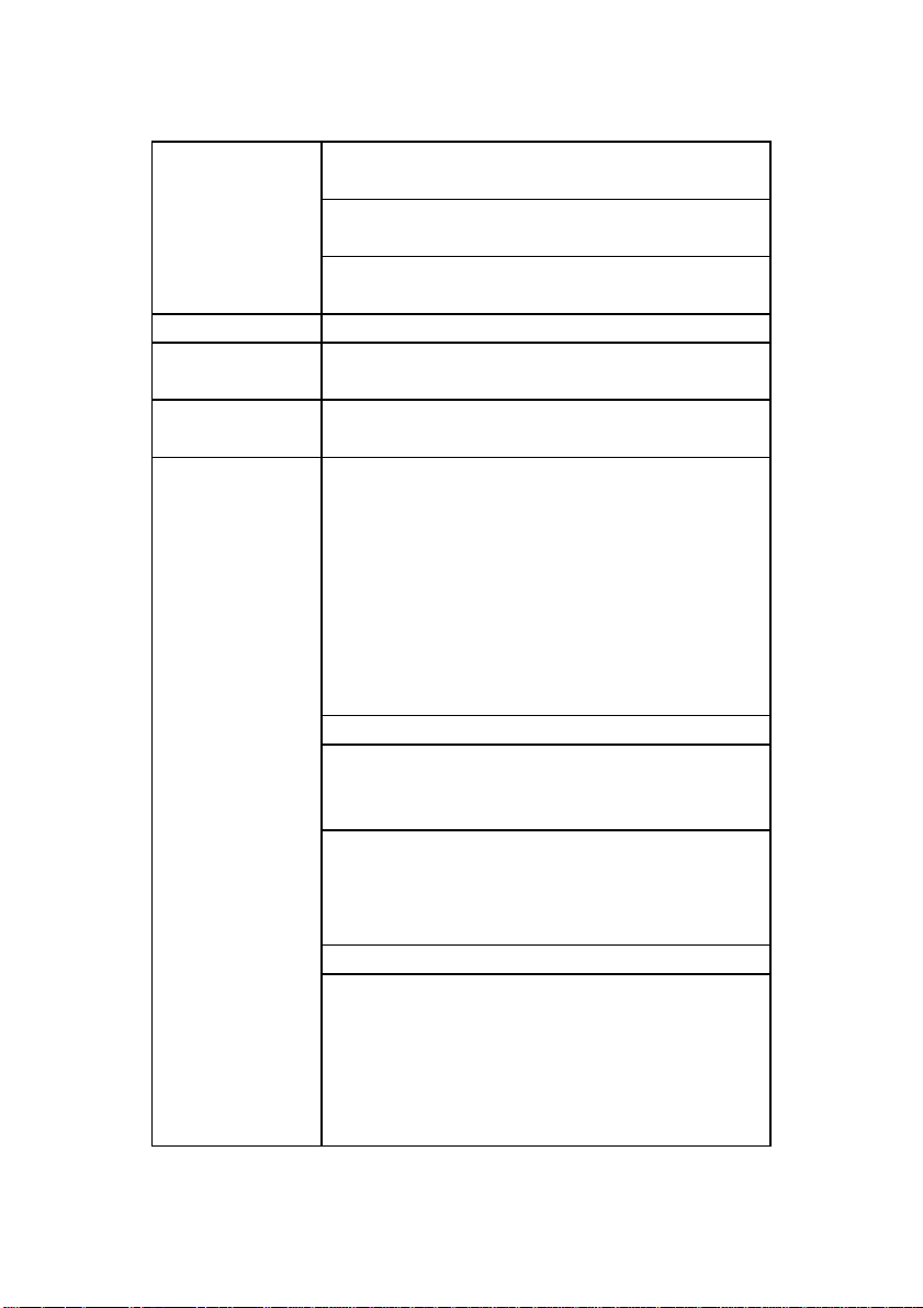
Page 6
Power Operation ( LCD backlight ON ) :
t
.
.
.
Consumption Approx. DC 32 mA
Operation ( LCD backlight OFF ) :
Approx. DC 8 mA
Power OFF ( only internal clock running ) :
Approx. DC 1.8 uA.
Weigh
* meter
1049 g/2.3 LB.
Dimension 225 X 125 X 64 mm
@ Meter
( 8.86 X 4.92 X 2.52 inch )
Accessories Instruction manual......................1 PC
Included
Optional * pH electrode.......................
Accessories PE-03, PE-11, PE-01, PE06HD
PE-04HD, PE-05T, PE-03K7
PE-02, PE-08, PE-21
* ATC ( Automatic Temperature
Probe )...............................
TP-07
* pH 7 buffer solution.............pH-07
* pH 4 buffer solution.............pH-04
* pH electrode hoder..............EH-20
* ORP electrode......................ORP-14
* Conductivity probe...............CDPB-03
* 1.413 mS Conductivity Standard
Solution..............................
CD-14
* Oxygen probe......................OXPB-11
* Spare Probe head with diaphragm set
..........................................OXHD-04
* Probe-filling Electrolyte........
OXEL-03
* Carrying case.......................CA-3K
* AC to DC 9V adapter.
* RS232 cable, UPCB-02.
*USB cable, USB-01
* Data Acquisition software,
SW-U801-WIN.
* Data Logger software, SW-DL2005.
4
Page 7
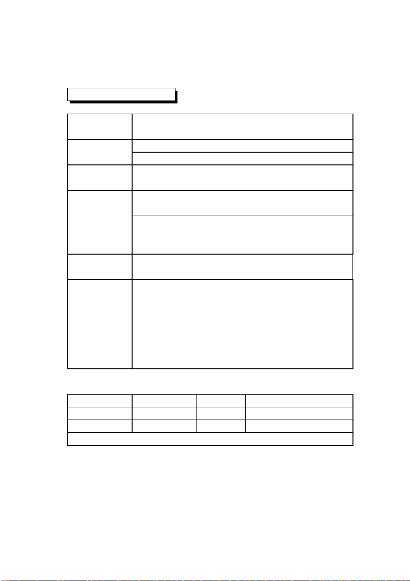
2-2 Electrical Specifications (23±5 )℃
A. pH/mV
pH Optional,
Electrode Any pH electrode with BNC connector.
Measurement pH 0 to 14 pH
mV -1999 mV to 1999 mV
Input 10^12 ohm
Impedance
Temperature Manual 0 to 100 , be adjusted by℃
Compensation push button on front panel.
for pH Automatic With the optional temperature
measurement ( ATC ) probe ( TP-07 )
0 to 65 .℃
pH pH7, pH4, and pH10, 3 points calibration
Calibration ensure the best linearity and accuracy.
Optional * pH electrode...........PE-03, PE-11, PE-01, PE06HD
probe and PE-04HD, PE-05T, PE-03K7
accessories * ATC ( automatic temperature
probe ).......................................TP-07
* pH 7 buffer solution....................pH-07
* pH 4 buffer solution....................pH-04
* ORP electrode.............................ORP-14
2-2 Electrical Specifications (23 ±5 )℃
Measurement Range Resolution Accuracy
pH 0 to 14 pH 0.01 pH ± (0.02 pH + 2 d)
mV 0 to 1999 mV 1 mV ± (0.5% + 2 d)
* pH accuracy is based on calibrated meter only.
5
Page 8
B. Conductivity
Conductivity Optional,
probe Carbon rod electrode for long life.
Function * Conductivity ( uS, mS )
* TDS ( Total Dissolved Solids, PPM )
* Temperature ( , )℃℉
Temperature Automatic from 0 to 60 (32 - 140 ),℃℉
Compensation with temperature compensation factor
variable between 0 to 5.0% per C.
Probe 0 to 60 .℃
Operating
Temperature
Probe Round, 22 mm Dia. x 120 mm length.
Dimension
Optional * Conductivity probe......................CDPB-03
probe and * 1.413 mS Conductivity Standard
accessories Solution......................................CD-14
1. Conductivity ( uS, mS )
Range Measurement Resolution Accuracy
200 uS 0 to 200.0 uS 0.1 uS
2 mS 0.2 to 2.000 mS 0.001 mS ± (2% F.S.+1d)
20 mS 2 to 20.00 mS 0.01 mS * F.S. - Full scale
200 mS 20 to 200.0 mS 0.1 mS
* Temperature Compensation :
Automatic from 0 to 60 ( 32 - 140 ), with temperature℃℉
compensation factor variable between 0 to 5.0% per C.
* The accuracy is specified under measurement value 100 mS.≦
* mS - milli Simens * @ 23± 5 ℃
6
Page 9
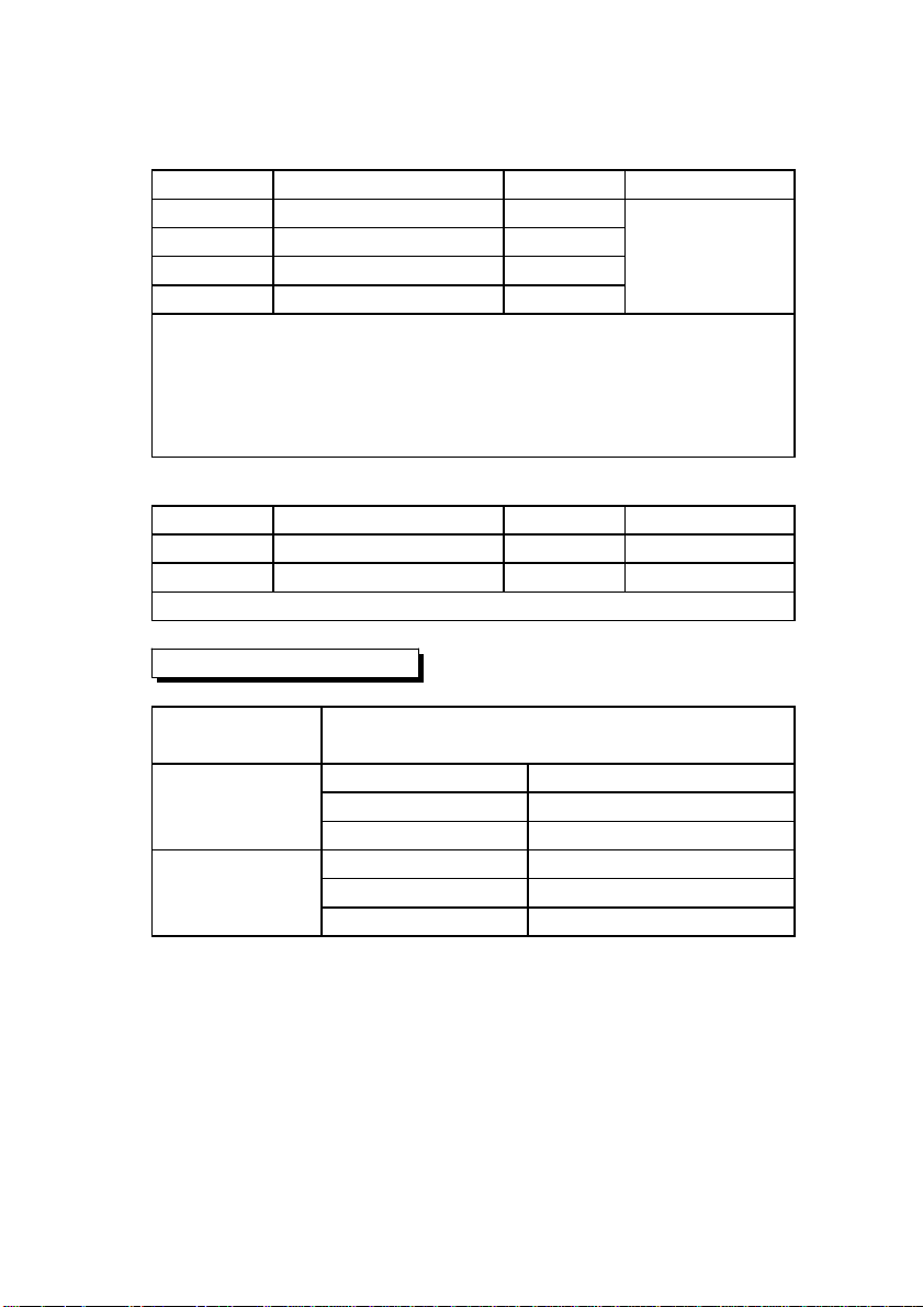
2. TDS ( Total Dissolved Solids )
Range Measurement Resolution Accuracy
200 PPM 0 to 132 PPM 0.1 PPM
2,000 PPM 132 to 1,320 PPM 1 PPM ± (2% F.S.+1d)
20,000 PPM 1,320 to 13,200 PPM 10 PPM * F.S. - Full scale
200,000 PPM 13,200 to 132,000 PPM 100 PPM
* Temperature Compensation :
Automatic from 0 to 60 ( 32 - 140 ), with temperature℃℉
compensation factor variable between 0 to 5.0% per .℃
* The accuracy is specified under measurement value 66,000 PPM.≦
* PPM - parts per million * @ 23± 5 ℃
3. Temperature
Function Measuring Range Resolution Accuracy
℃ 0 to 60 ℃℃ 0.1 ℃ ±0.8 ℃
℉ 32 to 140 ℉℉ 0.1 ℉ ±1.5 ℉
* @ 23± 5 ℃
C. Dissolved oxygen
Oxygen Optional,
Probe The polarograpHic type oxygen probe with
Measurement Dissolved Oxygen 0 to 20.0 mg/L ( liter ).
& Range Oxygen in Air 0 to 100.0 %.
Temperature 0 to 50 .℃
Resolution Dissolved Oxygen 0.1 mg/L.
Oxygen in Air 0.1 % O2 .
Temperature 0.1 .℃
7
Page 10
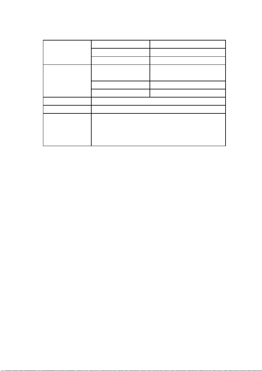
Accuracy Dissolved Oxygen ± 0.4 mg/L.
.
(23± 5 )℃ Oxygen in Air ± 0.7% O2.
Temperature ± 0.8 /1.5 .℃℉
Probe Temperature 0 to 50 ,℃
Compensation Automatic
& Adj. Salt 0 to 50 % Salt
Height ( M. T.) 0 to 8900 meter
Probe Weight 335 g/0.74 LB ( batteries & probe included )
Probe Size 190 mm x 28 mm Dia. ( 7.5" x 1.1" Dia. )
Optional * Oxygen probe.................................OXPB-11
Accessories * Spare Probe head with diaphragm set
.....................................................
* Probe-filling Electrolyte....................OXEL-03
OXHD-04
8
Page 11
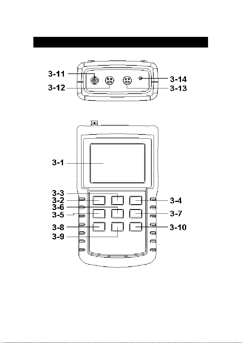
3. FRONT PANEL DESCRIPTION
Fig. 1-1
9
Page 12
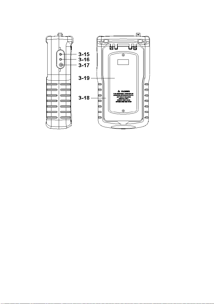
3-1 Display
3-2 Power Button ( LCD Backlight Button )
3-3 HOLD Button ( ESC Button )
3-4 REC Button ( Enter Button )
3-5 Mode Button ( Zero Button )
3-6 Function Button ( Range Button )
3-7 Send Button ( Clock Button )
3-8 SET Button ( Logger Button )
3-9 Up Button▲
3-10 Down Button ▼
3-11 PH Socket ( BNC Socket )
3-12 CD Socket
3-13 DO Socket
3-14 Temp. Socket ( pH ATC Socket )
3-15 RS232 socket
3-16 Reset button
3-17 DC 9V power adapter socket
3-18 Stand
3-19 Battery Cover/Battery compartment
Fig. 1-2
10
Page 13
4. MODE SELECTION
( pH/CD/DO selection )
1)Turn on the meter by pressing the " Power Button "
( 3-2, Fig. 1 ) momentarily.
*
Pressing the " Power Button " ( 3-2, Fig. 1 )
continuously and > 2 seconds again will turn off the
meter.
2)The meter can select 3 kind Mode as :
a. pH, mV ( ORP ) measurement
b. Dissolved Oxygen measurement
c. Conductivity, TDS measurement
Pressing the " Mode Button " ( 3-5, Fig. 1 ) once, the
Display will show the following text in sequence :
PH pH, mV ( ORP ) measurement
do Dissolved Oxygen measurement
Cd Conductivity, TDS measurement
Until the Display show the desired mode the meter will
execute this Mode with default.
11
Page 14
5. pH/mV MEASURING and
CALIBRATION PROCEDURE
The meter default function are following :
*The display unit is set to pH.
*The temperature unit is set to .℃
*Manual ATC ( without connect the ATC probe )
*Auto power off.
*The sampling time of data logger function is
2 seconds.
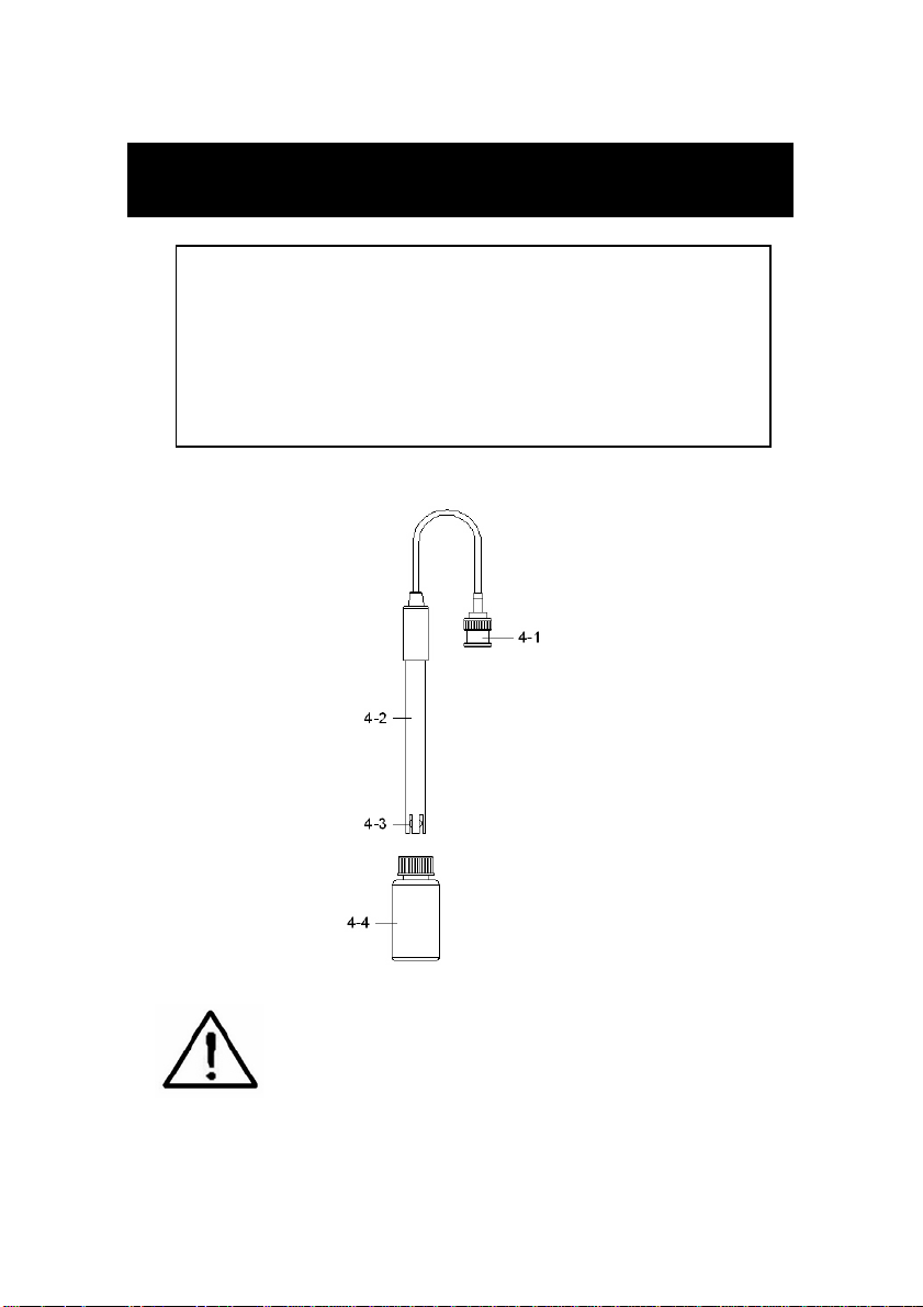
Fig. 2
If the meter is first time to connect
the pH electrode, it should make the
calibration before operation, the
calibration procedures refer chapter
5-4, page 14.
12
Page 15

5-1 pH measurement ( manual Temp compensation )
1)Prepare the pH Electrode ( optional ), install the
" Probe Plug " ( 4-1, Fig. 2 ) into the " pH Socket/BNC
Socket " ( 3-11, Fig. 1 ).
2)Power on the meter by pressing " Power Button "
( 3-2, Fig. 1 ) once.
Select the measurement mode to " pH, mV ( ORP )
measurement ". refer chapter 4, page 11.
The Display will show " pH " and " Temp. " indicator.
3)Adjust the manual Temp. value same as the
solution's temperature exactly, the procedures
refer chapter 9-7, page 38.
4)Hold the " Electrode Handle " ( 4-2, Fig. 2 ) by hand
and let the " Sensing head " ( 4-3, Fig. 2 ) immersed
wholly into the measured solution and little shake the
probe.
5)The up main display will show the pH value, the left
bottom display will show the setting manual Temp.
value.
5-2 pH measurement ( ATC , automatic Temperature )
1)All the procedures are same as
5-1 pH measurement ( manual ATC )
but should prepare one temperature probe ( optional,
TP-07 ), insert the TP-07's plug into the " Temp. Socket "
( 3-14, Fig. 1 ), immerse the sensing head of temperature
probe ( TP-07 ) into the measurement solution.
2)The up main display will show the pH value, the left
bottom display will show the sensing Temp. value of
the measured solution.
When not use the Electrode, it should immerse
the " Electrode sensing head " ( 4-3, Fig. 2 ) into
the " Protection bottle " ( 4-4, Fig. 2 )
13
Page 16

5-3 mV Measurement
The instrument build in mV ( millivolt ) measurement
function, which enable you to make ion-selective, ORP
(oxidation-reduction potential), and other precise mV
measurements.
1)Prepare the ORP Electrode ( optional, ORP-14 ), install
the " Probe Plug " of ORP electrode into the " pH
Socket/BNC Socket " ( 3-11, Fig. 1 ).
2)Power on the meter by pressing " Power Button "
( 3-2, Fig. 1 ) once.
Select the measurement mode to " pH, mV ( ORP )
measurement ". refer chapter 4, page 11 .
Pressing the " Function Button " ( 3-6, Fig. 1 )
once until the Display show " mV " indicator.
3)The up main display will show the mV value.
5-4 pH calibration
Calibration Consideration
The most ideal pH ELECTRODE generates 0 mV at pH
7.00 ( 177.4 mV at pH 4 ) and meter has been always
calibrated with signals which simulate the most ideal pH
ELECTRODE ( based on 25 ambient environment ).℃
However not every pH ELECTRODE is as accurate as the
most ideal one, so calibration procedures are necessary
to be done before the first time measurement.
In addition to the first time measurement, users are also
recommended to execute the calibration procedures to
ensure the high accuracy measurement.
14
Page 17

Required Equipment for Calibration
1)pH ELECTRODE ( optional ).
2)pH buffer solutions ( optional ).
Calibration Procedure
1)Prepare the pH Electrode ( optional ), install the
" Probe Plug " ( 4-1, Fig. 2 ) into the " pH Socket/BNC
Socket " ( 3-11, Fig. 1 ).
2)Power on the meter, set the mode to the pH
measurement, the right bottom display will show " pH ".
3)Adjust the " Temperature Compensation Value " to
make it same as the temperature value of the pH
buffer solution.
* Manual temperature compensation value
adjustment procedure, refer to 9-7, page 38.
* Automatic temperature compensation, refer
to 5-2, page 13.
.
4)Hold the " Electrode Handle " ( 4-2, Fig. 2 ) by hand
and let the " Sensing head " ( 4-3, Fig. 2 ) immersed
wholly into the measured solution and little shake the
probe.
Display will show the pH value.
* If use the ATC probe, should immerse the
ATC probe into the solution together.
15
Page 18

5)Use the two fingers to press the " REC Button " ( 3-4,
Fig 1 ) and " HOLD Button " ( 3-3, Fig. 1 ) at the
same time. Until Display will show the following screen
then release the both fingers.
PH
CAL
6)Press the " Button " ( 3-9, Fig. 1 ) or " Button " ▲▼
( 3-10, Fig. 1 ) once in sequence to select the following
screen.
a For pH 7.00 calibration
7.00
CAL
b For pH 4.00 calibration
4.00
CAL
c For pH 10.00 calibration
10.00
CAL
d Clear the existing calibration data
CLr
CAL
7)After the above a, b, c, d is selected, press the
" Enter Button " ( 3-4, Fig. 1 ) to execute the
calibration procedures.
16
Page 19

When select the
CLr
CAL
and press the " Enter Button " will clear the existing
calibration data.
7)Fine adjustment of calibration value
During the calibration when the main Display ( 7.00,
4.00 or 10.00 ) is flashed, it can use the " Button "▲
( 3-9, Fig. 1 ) or " Button " ( 3-10, Fig. 1 ) to make▼
the fine adjust of the calibration value, for example
the exact calibration value is 4.01, 4.02, 3.98....
7.01, 7.02. 6.98....10.01, 10.02, 9.98
After the fine calibration value is adjusted, release the
Button ( Button ), the main Display will be flashed▲▼
few second then execute the calibration according
the new calibration value.
7)The complete procedures should execute
the two calibration points :
pH7 calibration, pH4 calibration
pH7 calibration, pH10 calibration
* The calibration procedures should execute start from
pH7 calibration then follow pH4 ( or pH10 ) calibration.
* Rinse the electrode with distilled water again when
make each point calibration ( pH7, pH4 or pH10 ).
* Repeat above two points procedures two times at least.
17
Page 20

5-5 ORP calibration
1)Prepare the ORP electrode ( optional, ORP-14 ), connect
the ORP electrode to the meter.
2)Power on the meter, set the mode and the function
to " mV ", refer chapter 5-3, page 14.
3)Immerse the sensing head of ORP electrode into the
ORP standard buffer solution, the up display will
show the ORP value in mV.
4)Use the two fingers to press the " REC Button " ( 3-4,
Fig 1 ) and " HOLD Button " ( 3-3, Fig. 1 ) at the
same time. The display will show the following screen
as example, then release the both fingers.
OrP
CAL
5)Use " Button " ( 3-9, Fig. 1 ), " Button " ( 3-10,▲▼
Fig. 1 ) to adjust the up display value exact same as
the standard ORP buffer solution value. Press the
" Enter Button " will save the calibration the data
and finish the calibration procedures.
* The ORP calibration procedures are available
only the ORP buffer solution value is > 100 mV.
* If the ORP calibration procedures is less than
100 mV the calibration is not allow.
18
Page 21

6. CONDUCTIVITY/TDS MEASURING
and CALIBRATION PROCEDURE
The meter default function are following :
*The display unit is set to conductivity ( uS, mS ).
*The temperature unit is set to .℃
*Temp. compensation factor is set to 2.0% per C.
*Auto range.
*Auto power off.
*The sampling time of data logger function is
2 seconds.
Fig. 3
If the meter is first time to connect
the conductivity probe, it should
execute the calibration procedures
before operation, the calibration
procedures refer chapter 6-3, page 22.
19
Page 22

6-1 uS, mS measurement
1)Prepare the Conductivity Probe ( optional, CDPB-03 ),
install the " Probe Plug " ( 5-1, Fig. 3 ) into the
" CD Socket " ( 3-12, Fig. 1 ).
2)Power on the meter by pressing " Power Button "
( 3-2, Fig. 1 ) once.
Select the measurement mode to " Conductivity, TDS
measurement ". refer chapter 4, page 11.
The Display will show " uS " and " Temp. " indicator.
3)Hold the " Probe Handle " ( 5-2, Fig. 3 ) by hand
and let the " Sensing head " ( 5-3, Fig. 3 )
immersed wholly into the measured solution. Shake
the probe to let the probe's internal air bubble drift
out from the sensing head.
4)Display will show the conductivity mS ( uS ) values.
at the same time the left bottom display will show the
Temp. value of the measured solution.
Manual range operation
The meter is default to be used for the auto range
mode.
If intend to let the meter be used under the
manual range mode, the procedures are following :
*
Press the " Range Button " once a while, it can
change the range, the range name ( Auto, 200 uS, 2
mS, 20 mS, 200 mS ) will show under the
measurement value.
20
Page 23

* If the display shows " ", it indicates an
overload condition, select the next higher range.
* If the display shows " ", it indicates an
out-of-range, select the next lower range.
* If intend to change the operation mode from Manual
range back to Auto Range, press the " Range Button
" ( 3-6, Fig. 1 ) once in sequence until the Display
show the text " Auto ", release the " Range Button ",
the meter is ready for the Auto range mode again.
`
Change the Temp. unit to ℉
If intend to change the Temp. unit from to , please℃℉
refer page 37, chapter 9-6 ( Temp. Unit Default Setting )
Change the Temp. Coefficient Factor
The default Temp. compensation factor value of the
measurement solution is to 2.0% per . If intend to℃
change it, please refer page 39, chapter 9-11 ( Temp.
Compensation Factor Setting ).
Zero adjustment
If the probe not immerse the measurement solution
and display not show zero value, pressing the " Zero
Button " ( 3-5, Fig. 1 ) > 10 seconds continuously will
let display show zero. The zero function only valid when
the no zero value less than 1.0 uS.
21
Page 24

6-2 TDS ( PPM ) measurement
The measuring procedures are same as above
5-1 Conductivity ( uS, mS ) measurement,
except to change the display unit from uS, mS to PPM.
The procedures are :
* Press the " Function Button " ( 3-6, Fig. 1 ) > 2
seconds continuously until the Display show the text "
tdS ", then release the " Function Button " will enter the
the TDS measurement function.
* Under the TDS measurement, press the " Function
Button " ( 3-6, Fig. 1 ) > 2 seconds continuously until
the Display show the text " Cd ", then release the
" Function Button " will enter the Conductivity
measurement function again.
6-3 Calibration
1)Prepare the standard conductivity solution ( optional )
For example :
2 mS range calibration solution :
1.413 mS Conductivity Standard Solution, CD-14
200 uS range calibration solution :
80 uS Conductivity Standard Solution
20 mS range calibration solution :
12.88 mS Conductivity Standard Solution
or other Conductivity Standard Solution
2)Install the " Probe Plug " ( 5-1, Fig. 3 ) into the
" CD Socket " ( 3-12, Fig. 1 ).
3)Power on the meter, set the mode to the conductivity
measurement ( uS, mS ).
4)Hold the " Probe Handle " ( 5-2, Fig. 3 ) by hand
and let the " Sensing head " ( 5-3, Fig. 3 )
immersed wholly into the measured solution. Shake
the probe to let the probe's internal air bubble drift
out from the sensing head.
Display will show the conductivity mS ( uS ) values.
22
Page 25

5)Use the two fingers to press the " REC Button " ( 3-4,
*
*
Fig 1 ) and " HOLD Button " ( 3-3, Fig. 1 ) at the same
time. the display will show the following screen as
example, release the both fingers.
Cd
CAL
6)Use " Button " ( 3-9, Fig. 1 ), " Button " ( 3-10,▲▼
Fig. 1 ) to adjust the up display value exact same as
the standard conductivity value. Press the " Enter
Button " will save the calibration data and finish
the calibration procedures.
If only intend to make the one point calibration,
just execute the 2 mS range ( 1.413 mS Cal. )
is enough.
Multi-points calibration procedures should
execute the 2 mS range ( 1.413 mS Cal. )
calibration at first, then make other ranges
(20 uS range, 20 mS range or 200 mS range )
calibration procedures following if necessary.
23
Page 26

7. DO (Dissolved Oxygen)
MEASURING and CALIBRATION
PROCEDURE
1)Prepare the Oxygen Probe ( optional, OXPB-11 )
ATTENTION :
Fill the Probe's Electrolyte at first.
Intend to keep the DO probe under the
best condition, it should fill the
Probe's Electrolyte at first.
Probe-filling Electrolyte
Probe head with diaphragm set
The procedures that to fill the Probe's
Electrolyte, refer the chapter 7-3
" Probe maintenance ", page 29 .
24
Page 27

The meter default function are following :
*The display unit is set to mg/L.
*The temperature unit is set to .℃
*Auto power off.
*The sampling time of data logger function is
2 seconds.
7-1 Dissolved Oxygen measurement
Fig. 4
25
Page 28

1)Prepare the Oxygen Probe ( optional, DOPB-11 ),
install the " Probe Plug " ( 6-1, Fig. 4 ) into the
" DO Socket " ( 3-13, Fig. 1 ).
2)Power on the meter by pressing " Power Button "
( 3-2, Fig. 1 ) once.
Select the measurement mode to " Dissolved Oxygen
measurement ". refer chapter 4, page 11.
The Display will show " mg/L " and " Temp. " indicator.
Calibration at first !
Press the " Function Button " ( 3-6, Fig. 1 ) once,
the Display will show the " % O2 " indicator.
Wait approx. 2 minute until the reading value
reach stable, if the reading value not within
20.7 to 21.1 ( 20.9 ±0.2 ), then should be
processed the calibration procedures first.
The calibration procedures, please refer
chapter 7-2, page 28.
After execute the calibration procedures, the
display should show the value near 20.9
( 20.8 to 21.0 ).
3)Press the " Function Button " ( 3-6, Fig. 7 ) once,
the right low display will show the " mg/L " unit,
the meter is ready for the Dissolved Oxygen
measurement.
4)a. Immersed the probe to a depth at least 10 cm of
the measured liquid in order for the probe to be
influenced by the temperature & automatic
temperature compensation to take place.
26
Page 29

b.As for the thermal equilibrium to occur between the
probe & the measurement sample must be allowed
to pass, which usually amounts to a few minutes if
the Temp. difference between the two is only
several Celsius degrees.
5)a. In order to measure the dissolved oxygen content in
any given liquid, it is sufficient to immerse the tip of
the probe in the solution, making sure that velocity
of the liquid coming into contact with the probe is at
least 0.2 - 0.3 m/s or to shake the probe.
b.During laboratory measurements, the use of a
magnetic agitator to ensure a certain velocity in the
fluid is recommended. In this way, errors due to the
diffusion of the oxygen present in the air in the
solution are reduced to a minimum.
6)Display will show the Dissolved Oxygen values ( mg/L )
at the same time the left bottom display will show the
Temp. value of the measured solution.
7)Rinsed the probe accurately with normal tap water after
each series of measurement.
Oxygen in the air
When the display unit show " %O2 ", it show the
air Oxygen value approximately.
Change the Temp. unit to ℉
If intend to change the Temp. unit from to ,℃℉
please refer page 37, chapter 9-6 ( Temp. Unit
Default Setting )
27
Page 30

"% Salt" compensation value adjustment
If intend to change the % Salt compensation value,
refer page 38, chapter 9-8 ( % Salt Compensation
value Setting ).
"Height" compensation value adjustment
If intend to change the Height compensation value,
refer page 39, chapter 9-9, 9-10 ( Height Compensation
value Setting ).
7-2 Calibration
1)Install the " Probe Plug " ( 6-1, Fig. 4 ) into the
" DO Socket " ( 3-13, Fig. 1 ).
2)Power on the meter by pressing " Power Button "
( 3-2, Fig. 1 ) once.
Select the measurement mode to " Dissolved Oxygen
measurement ", the Display will show " mg/L " indicator.
Pressing the " Function Button " ( 3-6, Fig. 1 ) once
until the right bottom display show " %O2 ".
3)Wait for approx. 5 minutes at least until the
display reading values become stable & no
fluctuation.
4)Use the two fingers to press the " REC Button " ( 3-4,
Fig 1 ) and HOLD Button " ( 3-3, Fig. 1 ) at the same
time, the display will show the following screen as
example, release the both fingers.
20.9
CAL %O2
28
Page 31

5)Press the " Enter Button " ( 3-4, Fig. 1 ), the Display
.
value will count down from 30 to 0, then return to
normal measuring screen and finish the calibration
procedures. The complete calibration procedures will
take 30 seconds approximately.
After finish the calibration, press the " Function
Button " ( 3-6, Fig. 1 ) once, to let Display unit to
return " mg/L ".
Calibration Consideration :
a.As the oxygen in air is 20.9 % typically, so use
the environment air oxygen value for quick &
precise calibration.
Please process calibration procedures under
b
wide and ventilating environment for best effect.
7-3. Probe maintenance
User first time to use the meter :
Intend to let the DO probe keep the best
condition, when user receive the Oxygen Probe,
it should fill the Probe's Electrolyte at first.
User already use the probe for a certain
period :
Whenever user can not calibrate the meter
properly or the meter's reading value is not stable,
please check the oxygen probe to see if the
electrolyte in the probe head container is run out
or the diaphragm ( probe head with diaphragm
set) exist problem ( dirty ). If yes, please fill the
electrolyte or change the " Probe head with
diaphragm set " and make the new calibration.
29
Page 32

The consideration of diaphragm ( probe head
with diaphragm set ) :
The oxygen probe component is the thin Teflon
diaphragm housed in the tip of the probe. The
diaphragm is permeable by the oxygen molecules but
not by the considerably larger molecules contained in
the electrolyte. Due to this characteristic, the oxygen
may diffuse throughout the electrolyte solution
contained in the probe, and its concentration may be
quantified by the measurement circuit.
This sensitive diaphragm is rather delicate & is easily
damaged if it comes into contact with solid objects or is
subjected to blows. If the diaphragm is damaged or the
electrolyte is run out, it must be replaced in the following
way :
Probe-filling Electrolyte,
OXEL-03
Probe head with diaphragm set
1)Unscrew the " Probe head " ( 7-3, Fig 5 ).
2)Pour out the old Electrolyte from the
container of the " Probe head ".
3)Fill the new Electrolyte ( OXEL-03 )
into the container of the " Probe
head " .
30
Page 33

4)Screw the " Probe head " ( 7-3, Fig 5 )
)
into the probe body.
When not use the
5
probe, should insert
the " Probe head "
into the " Probe 7-1 Probe handle
protection cover " 7-2 Temp. sensing metal
( 6-5, Fig. 4 ) 7-3 Probe head
Fig. 5
8. DATA HOLD, DATA RECORD,
DATA LOGGER,
LCD BACKLIGHT
8-1 Data Hold
During the measurement, press the " Hold Button " ( 3-3,
Fig. 1 ) once will hold the measured value & the LCD will
display a " HOLD " symbol.
Press the " Hold Button " once again will release the data
hold function.
8-2 Data Record ( MAX, MIN reading )
* The data record function records the maximum and
minimum readings. Press the " REC Button " ( 3-4, Fig.
1 ) once to start the Data Record function and there
will be a " REC " symbol on the display.
* With the " REC " symbol on the display :
a)Press the " REC Button " ( 3-4, Fig. 1 ) once, the
" REC MAX " symbol along with the maximum value
will appear on the display.
If intend to delete the maximum value, just press
the " Hold Button " ( 3-3, Fig. 1 ) once, then the
display will show the " REC " symbol only & execute
the memory function continuously.
31
Page 34

b)Press the " REC Button " ( 3-4, Fig. 1 ) again, the
" REC MIN " symbol along with the minimum value
will appear on the display.
If intend to delete the minimum value, just press
the " Hold Button " ( 3-3, Fig. 1 ) once, then
the display will show the " REC " symbol only &
execute the memory function continuously.
c)To exit the memory record function, just press the
" REC " Button > 2 seconds at least. The display will
revert to the current reading.
8-3 Data Logger
The data logger function can save 16,000 measuring
data with the clock time ( Real time data logger, build
in clock ( hour-min.-sec., year-month-date ).
The data logger procedures are as following :
a)If push the " Logger Button " ( 3-8, Fig. 1 ) once will
show the sampling time value on the bottom left
display then disappeared.
b)Press the " REC Button " ( 3-4, Fig. 1 ) once to
start the Data Record function and there will be a
" REC " symbol on the display.
Auto Data Logger ( Sampling time set from
1 second to 8 hours 59 minutes 59 seconds )
Press the " Logger Button " ( 3-8, Fig. 1 ) once to start
the Auto Data Logger function, The upper display will
show " DATALOGGER " indicator along with " REC "
marker.
* Pause the data logger function :
Press the " Logger Button " ( 3-8, Fig. 1 ) once.
* Exit the data logger function :
Press the " REC Button " ( 3-4, Fig. 1 ) > 2 seconds.
32
Page 35

Manual Data Logger ( Sampling time set to 0
)
second )
Press the " Logger Button " ( 3-8, Fig. 1 ) once will
save the data one time into the memory.
Beeper will sound and the upper display will show
" DATALOGGER " indicator along with " REC " marker.
* Exit the data logger function :
Press the " REC Button " ( 3-4, Fig. 1 ) > 2 seconds.
d
Memory full
Under execute the data logger, if the bottom right
display show the " Full ", it indicate the memory data
already over 16,000 no. and the memory is full.
e)During execute the Auto Data Logger function, press the
Logger Button " ( 3-8, Fig. 1 ) once will stop to execute
" the data logger function, the " DATALOGGER " indicator
will be disappeared.
If press the " Logger Button " ( 3-8, Fig. 1 ) once again
will continuous the Auto Data Logger function.
Remark :
1)
If intend to change the data logger sampling time,
please refer chapter 9-4, page 36.
2)
If intend to know the space of balance data numbers
into the memory IC, please refer chapter 9-1, page 35.
3)
If intend to clear the saving data from the memory
please refer chapter 9-2, page 35.
8-4 LCD Bcklight ON/OFF
After power ON, the " LCD Backlight " will light
automatically. During the measurement, press the
" Backlight Button " ( 3-2, Fig. 1 ) once will turn OFF the
" LCD Backlight ".
Press the " Backlight Button " once again will turn ON the
" LCD Backlight " again.
33
Page 36

9. ADVANCED ADJUSTMENT
.
.
.
.
.
.
.
PROCEDURES
Under do not execute the Datalogger function,
press the " SET Button " ( 3-8, Fig. 1 ) continuously at
least two seconds will enter the " Advanced Setting " mode,
press the " SET Button " ( 3-8, Fig. 1 ) once a while
in sequence to select the 13 main function, the
display will show :
SPACE..
Clr........
dAtE.....
SP-t......Set sampling time ( Hour/Minute/Second )
PoFF.....Auto power OFF management
t-CF......Select the Temp. unit to or ℃℉
Check memory space
Clear Memory
Set clock time ( Year/Month/Date, Hour/Minute/
Second )
t-SEt.....Set pH manual Temp. compensation value, pH only
SALt.....
High-...
Set DO salt% compensation, DO only
Set DO height (meter) compensation, DO only
Highf....Set DO height (feet) compensation, DO only
PEr C....
tdS.......
ESC...... Escape from the advanced setting
Set CD temperature compensation factor, CD only
Set CD to TDS or TDS to CD, CD only
Remark :
a.DO - Dissolved oxygen Mode
CD - Conductivity/TDS Mode
pH - pH/mV Mode
34
Page 37

b.During execute the " Advanced Setting " function,
if press " ESC Button " ( 3-3, Fig. 1 ) will exit the
" Advanced Setting " function, the LCD will return
to normal screen.
9-1 Check memory space
When the display show " SPACE "
To check the balance data numbers that exist into the
memory ( allow the balance memorize data no. ).
@The bottom value XXXXX is the balance data numbers,
for example XXXXX=15417.
9-2 Clear Memory
When the display show " CLr "
1)To delete the existing save data numbers from the
memory.
2)Push ENTER Button to enter " Memory clear " function.
Use the " Button " ( 3-9, Fig. 1 ) or " Button " (▲▼
3-10, Fig. 1 ) to select the upper value to " yES " or
" no ".
yES - Intend to clear the Memory.
no - Not to clear the Memory.
3)If select the upper to " yES ", press the " Enter Button
" ( 3-4, Fig. 1 ) once will clear the Memory, the bottom
value will show " 0 ".
Press the ESC Button once to quite and return to
the main measurement screen.
35
Page 38

9-3 Set Date/Time ( Year/Month/Date,
Hour/Minute/ Second )
When the upper display show " dAtE "
1)Use the " Button " ( 3-9, Fig. 1 ) or " Button " ▲▼
( 3-10, Fig. 1 ) to adjust the value ( Setting start from
Year value ). After the desired value is set, press the
" Enter Button " ( 3-4, Fig. 1 ) once will going to
next value adjustment ( for example, first setting
value is Year then next to adjust Month, Date, Hour,
Minute, Second value ).
Remark :
The adjusted value will be flashed.
2)After set all the time value ( Year, Month, Date, Hour,
Minute, Second ), press the " SET Button " ( 3-8, Fig.
1 ) once will save the time value, then the screen will
jump to Sampling time " setting screen ( Chapter 9-4 ).
Remark :
After the time value is setting, the internal clock will
run precisely even Power off if the battery is under
normal condition ( No low battery power ).
9-4 Set sampling time ( Hour/Minute/Second )
When the upper display show " SP-t "
1)Use the " Button " ( 3-9, Fig. 1 ) or " Button " ▲▼
( 3-10, Fig. 1 ) to adjust the value ( Setting start from
Hour value ). After the desired value is set, press the
" Enter Button " ( 3-4, Fig. 1 ) once will going to next
value adjustment ( for example, first setting value is
Hour then next to adjust Minute, Second value ).
36
Page 39

Remark :
The adjusted value will be flashed.
2)After set all the sampling time value ( Hour, Minute,
Second ), press the " SET Button " ( 3-8, Fig. 1 ) once
will save the sampling value with default then the
screen will jump to " Auto power OFF " setting
screen ( Chapter 9-5 ).
9-5 Auto power OFF management
When the lower display show " PoFF "
1)Use the " Button " ( 3-9, Fig. 1 ) or " Button " ▲▼
( 3-10, Fig. 1 ) to select the upper value to " yES " or
" no ".
yES - Auto Power Off management will enable.
no - Auto Power Off management will disable.
2)After select the upper text to " yES " or " no ", press the
" Enter Button " ( 3-4, Fig. 1 ) will save the setting
function with default.
9-6 Select the Temp. unit to or ℃℉
When the lower display show " t-CF "
1)Use the " Button " ( 3-9, Fig. 1 ) or " Button " ▲▼
( 3-10, Fig. 1 ) to select the upper Display text to " C " or
" F ".
C - Temperature unit is ℃
F - Temperature unit is ℉
37
Page 40

2)After Display unit is selected to " C " or " F ", press the
" Enter Button " ( 3-4, Fig. 1 ) will save the setting
function with default.
9-7 Set pH manual Temp. compensation value
When the lower display show " t-SEt "
1)This function only for the pH measurement of
adjusting the pH electrode's manual Temp.compensation
value. The default value is 25 ( 77 ).℃℉
2)Use the " Button " ( 3-9, Fig. 1 ) or " Button " ▲▼
( 3-10, Fig. 1 ) to select the upper value to the desired
Temp. compensation value ( or ), then press the ℃℉
" Enter Button " ( 3-4, Fig. 1 ) will save the setting
value with default.
9-8 Set DO salt% compensation value
When the lower display show " SALt "
1)This function only for the DO ( Dissolved oxygen ) mode
of adjusting the probe's salt% compensation value.
The default value is 0% salt.
2)Use the " Button " ( 3-9, Fig. 1 ) or " Button " ▲▼
( 3-10, Fig. 1 ) to select the upper value to the desired
salt% compensation value, then press the " Enter
" Enter Button " ( 3-4, Fig. 1 ) will save the setting
value temporally.
38
Page 41

9-9 Set DO height ( meter ) compensation value
When the lower display show " High- "
1)This function only for the DO ( Disolved oxygen ) mode
of adjusting the probe's height compensation value in
meter unit. The default value is 0 meter.
2)Use the " Button " ( 3-9, Fig. 1 ) or " Button " ▲▼
( 3-10, Fig. 1 ) to select the upper value to the desired
height compensation value ( meter ), then press the
" Enter Button " ( 3-4, Fig. 1 ) will save the setting
value temporally.
9-10 Set DO height ( feet ) compensation value
When the lower display show " Highf "
1)This function only for the DO ( Dissolved oxygen ) mode of
adjusting the probe's height compensation value in
feet unit. The default value is 0 FEET.
2)Use the " Button " ( 3-9, Fig. 1 ) or " Button " ▲▼
( 3-10, Fig. 1 ) to select the upper value to the desired
height compensation value ( feet ), then press the
" Enter Button " ( 3-4, Fig. 1 ) will save the setting
value temporally.
39
Page 42

9-11 Set CD temperature compensation factor
When the lower display show " PEr C "
1)This function only for the Conductivity ( TDS ) mode of
adjusting the probe's Temp. compensation value in
%/per unit. The default value is 2 %/ per .℃℃
2)Use the " Button " ( 3-9, Fig. 1 ) or " Button " ▲▼
( 3-10, Fig. 1 ) to select the upper value to the desired
Temp. compensation value ( %/per ), then press the ℃
" Enter Button " ( 3-4, Fig. 1 ) will save the setting
value temporally.
9-12 ESC
When the display show " ESC "
When the Display show the text " ESC ", then press the
" Enter Button " ( 3-4, Fig. 1 ) will finish the Advanced
Setting procedures and return to the normal measuring
screen.
40
Page 43

10. SEND THE DATA OUT FROM
THE METER
1)If intend to send the data out from the meter, it
should exit the " Hold function " and the " Record
function " first. The display should be not show the
" HOLD " and the " REC " marker.
2)Press the " SEND Button " ( 3-7, Fig. 1 ) at least 2
seconds until the Display show " SEnd ", then release
the Button.
LCD display will show the following screen :
188 Data no. that saved into the block.
3Block no.
Use " Up Button", " Down Button " to select▲▼
the different data memory block no. ( 1 to 250 ).
The meter can save 16,000 data Max. , those
data will saved into 250 memory blocks max..
*" One " Memory Block " means :
Execute the Data logger function ( Push " REC "
Button, following push the " Logger " Button to save
the data..... . ) will generate the first Memory block
* Exit the Data logger function and execute
the Data logger function again will generate the
second Memory " Block " again.
41
Page 44

Block 1 Data 1
@
@
to
Data X
↓
Block 2 Data X+1
to
Data Y
↓
..................
..................
↓
Block 250 Data Z
to
Data 16,000
3)Until the desired Memory Block no. be selected.
Push the " Send Button " ( 3-7, Fig. 1 ) once, the
data in the Memory Block will send out.
During the data send out, the bottom display will show
the " SEend " indicator, the upper value ( Data no. that
saved into the Block ) will count down until zero.
4)Push the " ESC Button " ( 3-3, Fig. 1 ) will exist
the data sending function and return to the normal
display.
Remarks :
If intend to load the data to the computer,
should connect the RS232 cable
( optional, model : UPCB-02) or the USB cable
( optional, model : USB-01 ) and apply the
Data Logger software ( optional, Model :
SW-DL2005 ).
When sending the data, each time just can
send one Memory Block data out. for example
block 1 data, block 2 data... or block 250 data.
42
Page 45

11. RS232 PC SERIAL INTERFACE
The instrument has RS232 PC serial interface via the
RS-232 Out Terminal " ( 3-15, Fig. 1 ).
The data output is a 16 digit stream which can be
utilized for user's specific application.
A RS232 lead with the following connection will be
required to link the instrument with the PC serial port.
Meter PC
(3.5 mm jack plug) (9W 'D" Connector)
Center Pin........................Pin 4
Ground/shield.....................Pin 2
2.2 K
resister
Pin 5
The 16 digits data stream will be displayed in the
following format :
D15 D14 D13 D12 D11 D10 D9 D8 D7 D6 D5 D4 D3 D2 D1 D0
43
Page 46

Each digit indicates the following status :
D15 Start Word = 02
D14 4
D13 When send the upper display data = 1
When send the lower display data = 2
D12, D11 Annunciator for Display
uS = 13 mS = 14 PPM = 19
pH = 05 mV = 18
mg/L = 07 % O2 = 06
D10 Polarity
0 = Positive 1 = Negative
D9 Decimal Point(DP), position from right to the
left
0 = No DP, 1= 1 DP, 2 = 2 DP, 3 = 3 DP
D8 to D1 Display reading, D1 = LSD, D8 = MSD
For example :
If the display reading is 1234, then D8 to
D1 is : 00001234
D0 End Word = 0D
RS232 setting
Baud rate 9600
Parity No parity
Data bit no. 8 Data bits
Stop bit 1 Stop bit
44
Page 47

12. BATTERY REPLACEMENT
1)When the left corner of LCD display show " ", it
is necessary to replace the batteries ( UM3/1.5 V x 8 PCs ).
2)Slide the " Battery Cover " ( 3-19, Fig. 1 ) away from the
instrument and remove the batteries.
3)Replace with batteries ( UM3/1.5 V x 8 PCs )
and reinstate the cover.
4)Make sure the battery cover is secured after changing
the battery.
13. SYSTEM RESET
If the meter happen the troubles such as :
CPU system is garbled ( for example, the key Button can
not be operated..... ).
Then make the system RESET will fix the problem.
The system RESET procedures are as following.
Used a pin tool to push the " System Reset
Switch " ( 3-16, Fig. 1 ) once a while then
power on again will fix the problem.
45
Page 48

14. OPTIONAL ACCESSORIES
RS232 cable * Computer interface cable.
UPCB-02 * Used to connect the meter to
the computer ( COM port ).
USB cable * Computer interface cable.
USB-01 * Used to connect the meter to
the computer ( USB port ).
Data Logger * Software the used to download
software the data logger ( data recorder )
SW-DL2005 from the meter to computer.
Data Acquisition * The SW-U801-WIN is a multi
software displays ( 1/2/4/6/8 displays )
SW-U801-WIN powerful application software,
provides the functions of data
logging system, text display,
angular display, chart display,
data recorder high/low limit, data
query, text report, chart report..
.xxx.mdb data file can be
retrieved for EXCEL, ACESS..,
wide intelligent applications.
Power adapter AC 110V to DC 9V
USA plug
Power adapter AC 220V/230V to DC 9V
Germany plug
Carrying case Soft carrying case
Model : CA-3K
Electrode holder Electrode holder for all pH
electrodes and the ATC Temp. probe.
Model : EH-20
46
Page 49

pH *pH Electrode, 1 to 13 pH.
optional Model : PE-11
accessories *pH Electrode, 1 to 13 pH.
Model : PE-03
*pH Electrode, 0 to 14 pH.
Model : PE-01
*Glass body heavy duty pH Electrode,
0 to 14 pH.
Model : PE-02
*Glass body plane pH Electrode,
0 to 14 pH.
Model : PE-08
*Industrial in line pH Electrode,
0 to 14 pH.
Model : PE-21
*SPEAR pH Electrode
Model : pH-06HD, pH-04HD
*pH Electrode + Temp. probe, 2 in 1
Model : PE-03K7
*pH Electrode + Temp. probe, 2 in 1
Model : PE-05HT
*pH 7 BUFFER SOLUTION
Model : pH-07
*pH 4 BUFFER SOLUTION
Model : pH-04
*Temperature probe ( ATC probe )
Model : TP-07
Conductivity *Conductivity probe
optional Model : CDPB-03
accessories *1.413 mS standard solution.
Model : CD-14
Dissolved *Oxygen probe
Oxygen Model : OXPB-11
optional *Spare Probe head with DiapHragm set
accessories Model : OXHD-04
*Probe-filling Electrolyte
Model : OXEL-03
47
0907-WA2015
 Loading...