

Page 1
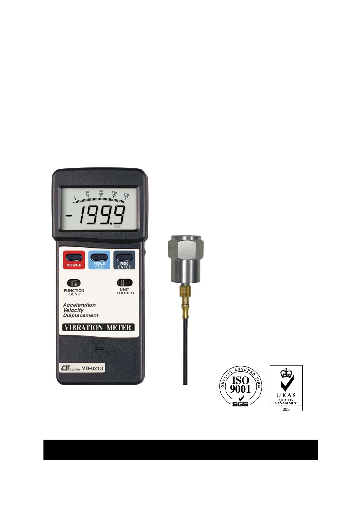
Acceleration/Velocity/Displacement
V
Y
f
A
f
RMS/Peak/Max. Hold, Metric & Imperial unit
IBRATION METER
Model : VB-8213
our purchase of this
VIBRATION METER
marks a step forward for
you into the field o
precision measurement.
lthough this METER is
a complex and delicate
instrument, its durable
structure will allow
many years of use i
proper operating
techniques are
developed. Please read
the following
instructions carefully
and always keep this
manual within easy
reach.
OPERATION MANUAL
Page 2

TABLE OF CONTENTS
.
.
.
.
.
.
.
.
1 FEATURES.................................................................1
2 SPECIFICATIONS......................................................
2-1 General Specifications..........................................2
2-2 Electrical Specifications........................................ 4
3 FRONT PANEL DESCRIPTION..................................... 7
3-1 Display...............................................................
3-2 Power Button...................................................... 8
3-3 Hold/ESC Button ................................................
3-4 REC/ENTER Button .............................................8
3-5 FUNCTION/SEND Button......................................8
3-6 UNIT/LOGGER Button..........................................8
3-7 Battery Cover/Compartment.................................8
3-8 RS232 Output terminal........................................
3-9 BNC socket of meter............................................8
3-10 BNC plug of cable.............................................. 8
3-11 Mini plug of cable..............................................
3-12 Input socket of vibration sensor..........................8
3-13 Vibration sensor................................................
3-14 Magnetic base................................................... 8
2
8
8
8
8
8
4.MEASURING PROCEDURE.......................................... 9
5.ZERO ADJUSTMENT PROCEDURE............................... 11
6.POWER MANAGEMENT..............................................
7.DATA LOGGER..........................................................
8.HOW TO SEND THE DATA OUT FROM THE METER......14
9.RS232 PC SERIAL INTERFACE....................................15
10. BATTERY REPLACEMENT.........................................19
11. OPTIONAL ACCESSORIES........................................19
12. CLASSIFICATION RANGES.......................................20
13. SENSITIVITY RELATIVE TABLE ACCORDING
ISO 2954...............................................................21
12
12
Page 3

1. FEATURES
*Applications for industrial vibration monitoring :
All industrial machinery vibrates. The level of vibration is
a useful guide to machine condition. Poor balance,
misalignment & looseness of the structure will cause the
vibration level increase, it is a sure sign that the
maintenance is needed.
*Frequency range 10 Hz - 1 kHz, sensitivity relative meet
ISO 2954.
*Professional vibration meter supply with vibration sensor
& magnetic base, full set.
*Metric & Imperial display unit
*Acceleration, Velocity, Displacement measurement.
*RMS, Peak value, Max. hold measurement.
*Wide frequency range.
*Data hold button to freeze the desired reading.
*Memory function to record maximum and minimum
reading with recall.
*Separate vibration probe with magnetic base,
easy operation.
*RS 232 computer interface.
*Data Logger.
*Optional data acquisition software.
*Optional data logger ( data collection ) software.
*Super large LCD display with bar graph indicator.
*Microcomputer circuit, high performance.
*Auto shut off saves battery life.
*Built-in low battery indicator.
*Heavy duty & compact housing case.
*Complete set with the hard carrying case.
1
Page 4
2. SPECIFICATIONS
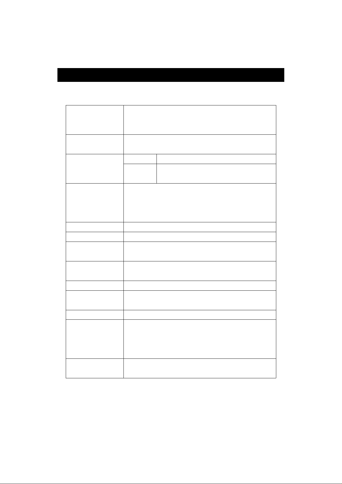
2-1 General Specifications
Display 52 mm x 38 mm, LCD display.
16 mm ( 0.63" ) digit size.
With bar graph indicator.
Measurement Velocity, Acceleration, Displacement
Function
Frequency 10 Hz to 1 KHz
range
Main
Others
RMS, Peak, Max. Hold.
Data hold, Max. & Min. value,
Data logger.
* Sensitivity relative during the
the frequency range meet ISO 2954
Refer to table 1, page 21.
Circuit Exclusive microcomputer circuit.
Data hold Freeze the desired reading.
Peak To measure the peak value.
measurement
Max. hold To measure and update the max. peak
measurement value.
Memory Maximum & Minimum value.
Power off Auto shut off, saves battery life,
or manual off by push button.
Sampling time Approx. 1 second.
Sampling Time 0, 1, 2, 10, 30, 60, 600, 1800, 3600 sec.
of Data Logger
* 0 second : Manual data logger.
* Other sampling time beyond 0
second : Auto data logger.
Data Logger 500 no. max.
No.
2
Page 5
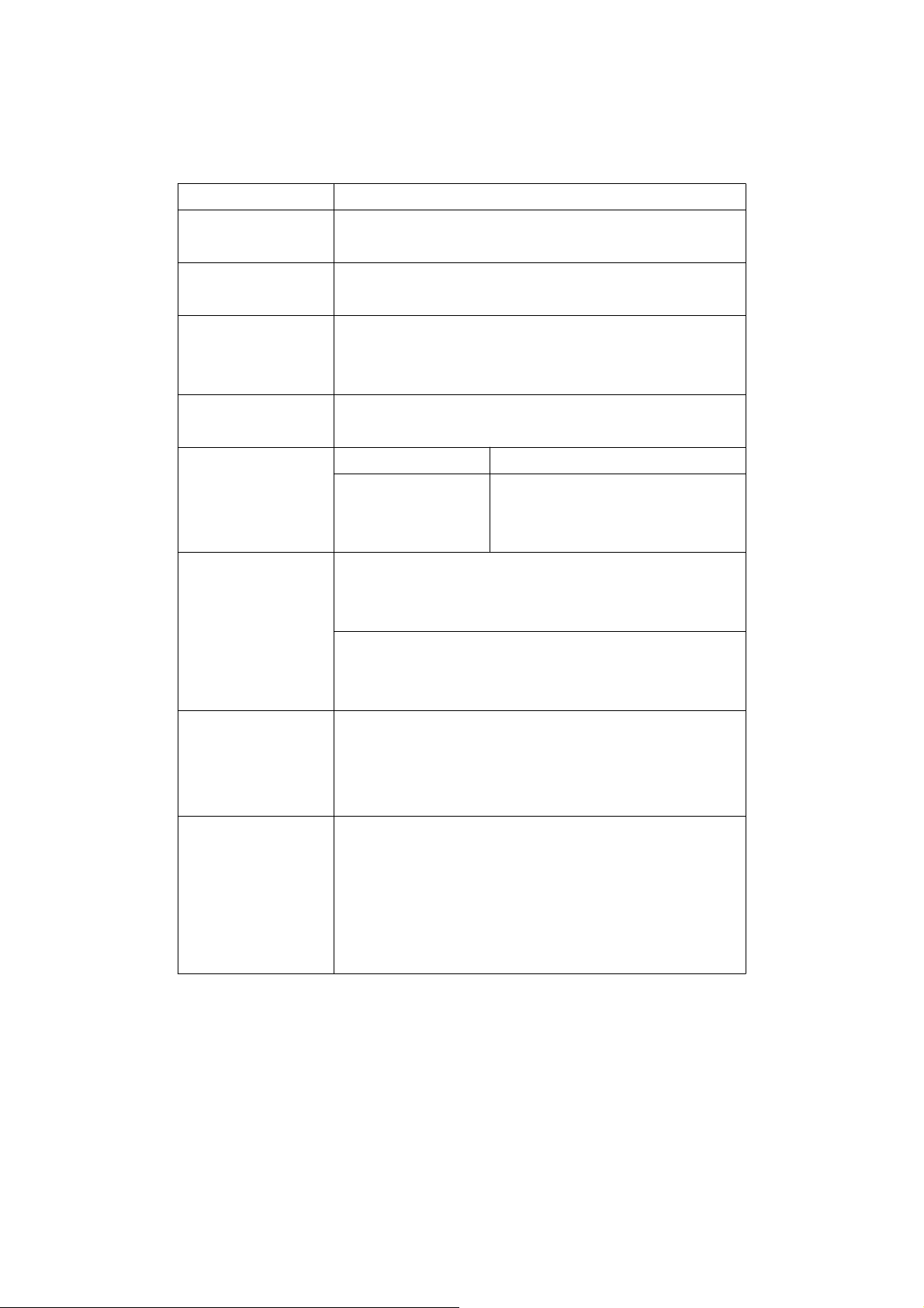
Data output RS 232 serial output, isolate.
.
Operating 0 to 50 ( 32 to 122 ).℃℉
temperature
Operating Less than 80% RH.
humidity
Power supply Alkaline or heavy duty type,
DC 9V battery, 006P,
MN1604 (PP3) or equivalent.
Power Approx. DC 13 mA.
consumption
Weight Meter 230 g/0.50 LB
Probe with 38 g/0.09 LB
cable and
magnetic base
Dimension Meter :
180 x 72 x 32 mm
( 7.1 x 2.8 x1.3 inch ).
Vibration sensor probe:
Round 19 mm Dia. x 21 mm.
Accessories Instruction manual.................. 1 PC.
included Vibration sensor with cable...... 1 PC.
Magnetic base......................... 1 PC.
Carrying Case.........................
Optional *RS232 cable, UPCB-01
accessories *USB cable, USB-01
*Data Acquisition software,
SW-801-WIN
*Data Logger ( data collection )
software, DL-2005.
3
1 PC.
Page 6
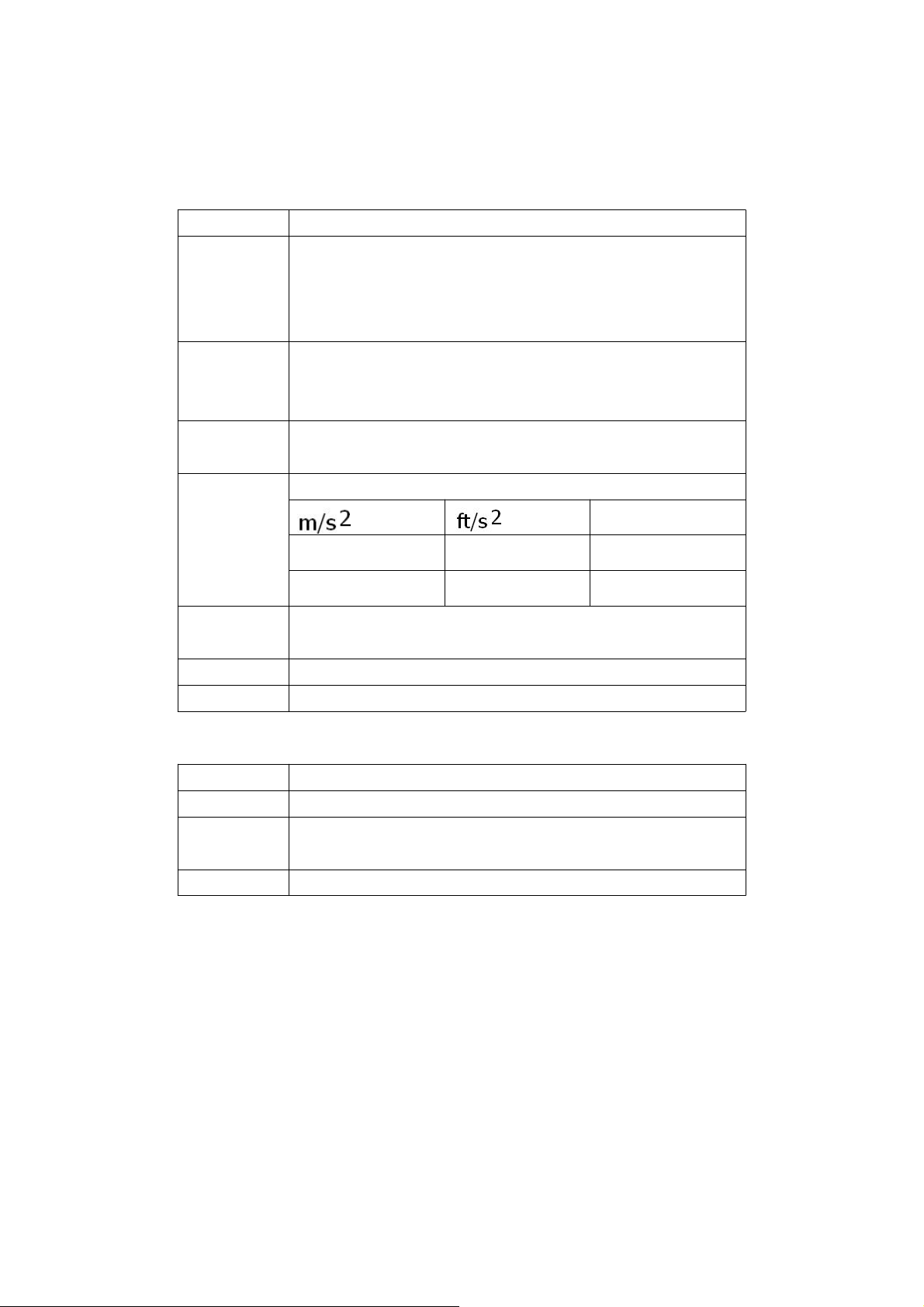
2-2 Electrical Specifications
50 ( 160 Hz )
50 ( 160 Hz )
50 ( 160 Hz )
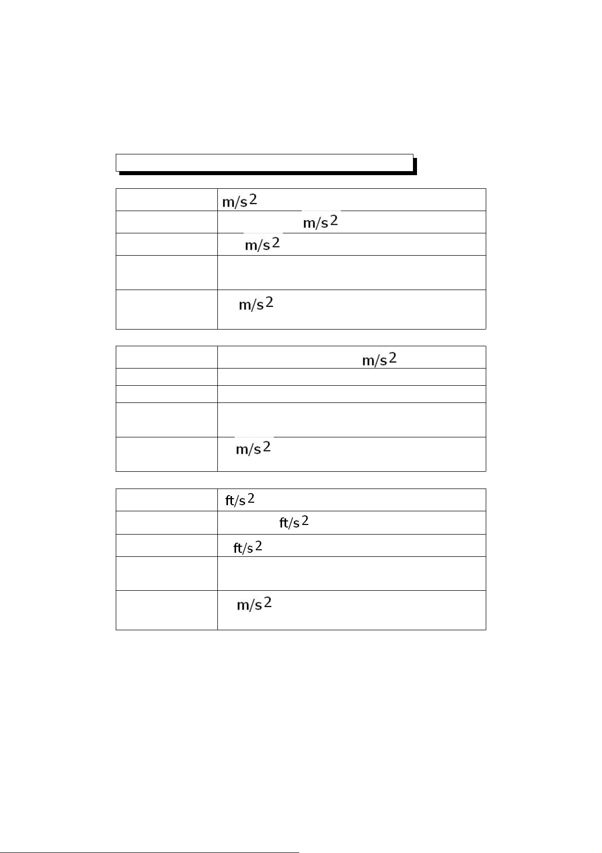
Acceleration ( RMS, Peak, Max Hold )
Unit
Range 0.5 to 199.9
Resolution 0.1
Accuracy ± ( 5 % + 2 d ) reading
@ 160 Hz, 80 Hz, 23 ± 5 ℃
Calibration
Point
Unit G
Range 0.05 to 20.39 G
Resolution 0.01 G
Accuracy ± ( 5 % + 2 d ) reading
@ 1 G = 9.8
@ 160 Hz, 80 Hz, 23 ± 5 ℃
Calibration
Point
Unit
Range 2 to 656
Resolution 1
Accuracy ± ( 5 % + 2 d ) reading
@ 160 Hz, 80 Hz, 23 ± 5 ℃
Calibration
Point
4
Page 7
Velocity ( RMS, Peak, Max Hold )
Unit mm/s
Range 0.5 to 199.9 mm/s
Resolution 0. 1 mm/s
Accuracy ± ( 5 % + 2 d ) reading
@ 160 Hz, 80 Hz, 23 ± 5 ℃
Calibration 50 mm/s ( 160 Hz )
Point
Unit cm/s
Range 0.05 to 19.99 cm/s
Resolution 0. 01 cm/s
Accuracy ± ( 5 % + 2 d ) reading
@ 160 Hz, 80 Hz, 23 ± 5 ℃
Calibration 50 mm/s ( 160 Hz )
Point
Unit inch/s
Range 0.02 to 7.87 inch/s
Resolution 0.01 inch/s
Accuracy ± ( 5 % + 2 d ) reading
@ 160 Hz, 80 Hz, 23 ± 5 ℃
Calibration 50 mm/s ( 160 Hz )
Point
5
Page 8

Displacement p-p ( RMS, Max Hold )
Unit mm
Range 1.999 mm
Resolution 0.001 mm
Accuracy ± ( 5 % + 2 d ) reading
@ 160 Hz, 80 Hz, 23 ± 5 ℃
Calibration 0.141 mm ( 160 Hz )
Point
Unit inch
Range 0.078 inch
Resolution 0.001 inch
Accuracy ± ( 5 % + 2 d ) reading
@ 160 Hz, 80 Hz, 23 ± 5 ℃
Calibration 0.141 mm ( 160 Hz )
Point
* Remark :
p-p = Peak to Peak
6
Page 9
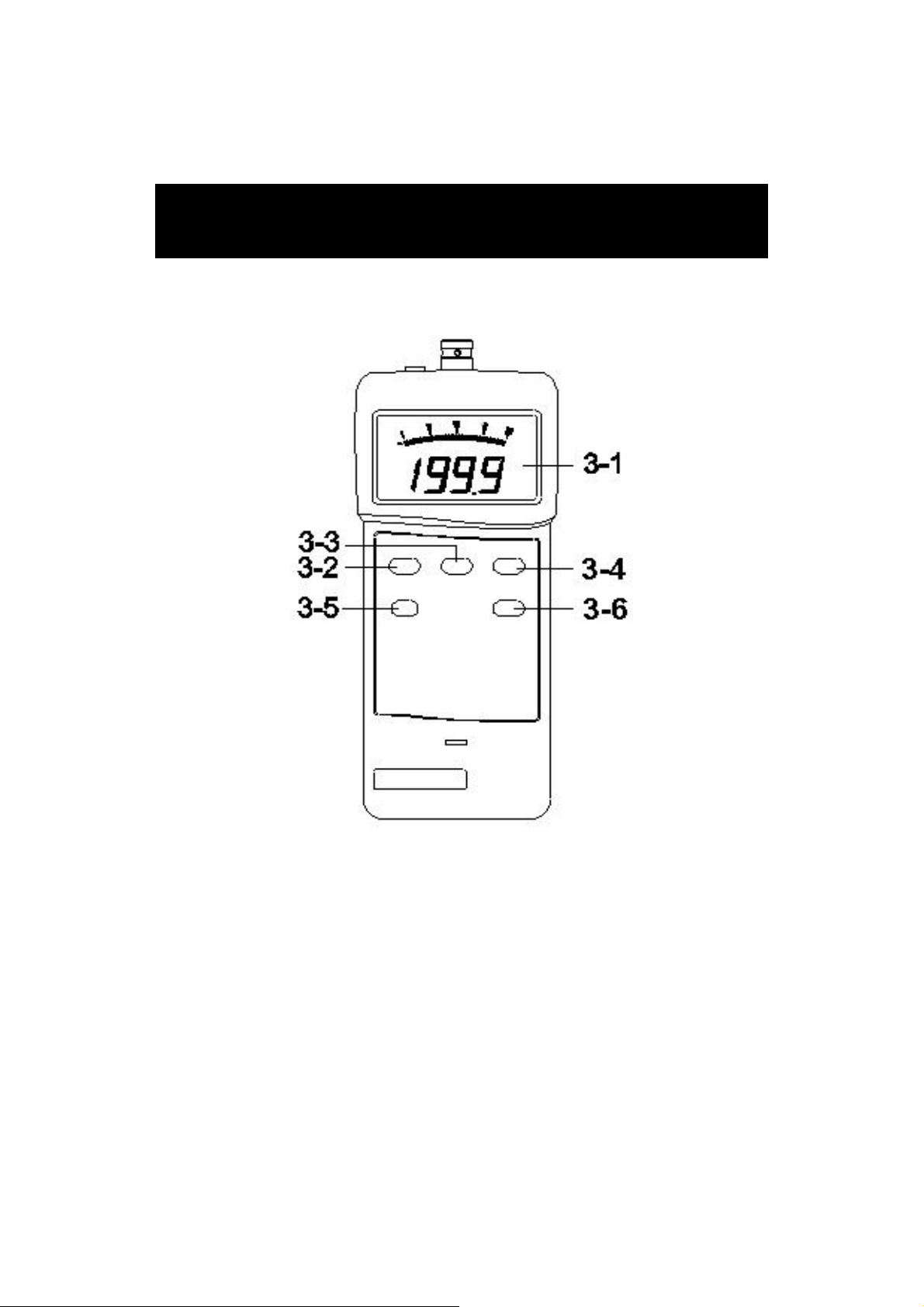
3. FRONT PANEL & LAYOUT
DESCRIPTION
Fig. 1
7
Page 10

3-1 Display
3-2 Power Button
3-3 Hold/ESC Button
3-4 REC/ENTER Button
3-5 FUNCTION/SEND Button
3-6 UNIT/LOGGER Button
3-7 Battery Cover/Compartment
3-8 RS232 Output terminal
3-9 BNC socket of meter
3-10 BNC plug of cable
3-11 Mini plug of cable
3-12 Input socket of vibration sensor
3-13 Vibration sensor
3-14 Magnetic base
Fig. 2
8
Page 11

4. MEASURING PROCEDURE
.
1)Plug in the " BNC plug of cable " ( 3-10, Fig. 2 ) to the
" BNC socket of meter " ( 3-9, Fig. 1 ).
2)Plug in the " Mini plug of cable " ( 3-11, Fig. 2 )
to the " Input socket of vibration sensor " ( 3-12, Fig. 2 ).
3)Power on the meter by press the " Power Button "
( 3-2, Fig. 1 ) once a while.
4) *If the surface material of measuring article is not
the ferrous material, hold the vibration sensor by
hand & touch the sensor to the surface of the
measuring article,
*If the surface material of measuring article is the ferrous
material, connect " Vibration sensor " ( 3-13, Fig. 2 )
with the " Magnetic base " ( 3-14, Fig. 2 ).
Put the whole unit ( Vibration sensor & Magnetic
base ) to the surface of measuring article.
5)FUNCTION SELECTION :
Select the desired function ( RMS, PEAK, MAX-HOLD )
by pressing the " FUNCTION Button " ( 3-5, Fig. 1 ).
Remarks :
a
For general applications of industrial vibration
monitoring, select " RMS " typically.
b. PEAK measurement is intend to measure the
peak vibration value.
c. MAX HOLD measurement is intend to measure and
update the max. peak value.
d. For the " Displacement " measurement only can
select the ' RMS " and " MAX HOLD " function only.
9
Page 12

5)UNIT SELECTION :
change the Metric unit ( , G, mm/s, cm/s, mm ) to
Imperial unit ( , inch/s, inch ) each other.
the LCD will indicate " " symbol.
Push the " Data hold button " again to release the
Select the desired display unit by pressing the " UNIT
Button " ( 3-6, Fig. 1 ).
The unit can be selected as :
Measurement Metric unit Imperial unit
Acceleration , G
Velocity mm/s, cm/s inch/s
Displacement mm inch
Remarks :
For general applications of industrial vibration
monitoring, select " Velocity " or " Acceleration "
typically.
How to change the Metric unit to Imperial
unit each other
If press the " UNIT Button" ( 3-6, Fig. 1 )
continuously at least 5 seconds, then will
6)Data Hold :
During the measurement, push the " Hold button "
( 3-3, Fig. 1 ) will hold the measured value &
data hold function.
10
Page 13

7)Data Record ( Max., Min. reading )
The DATA RECORD function displays the maximum,
and minimum readings.
a.Get into RECORD mode by momentarily pressing
" REC Button " ( 3-4, Fig. 1 ) once. REC icon will be ON.
b.Get out RECORD mode by pressing and hold " REC
Button " ( 3-4, Fig. 1 ) for 2 seconds. REC icon will
be OFF.
c. During RECORD mode ( REC icon ON ), momentarily
pressing " REC Button " to get into Max/Min mode, MAX
( both MAX and REC icons ON ) and MIN ( both MIN
and REC icons ON) cycling. Momentarily pressing
" HOLD Button " ( 3-3, Fig, 1 ) to leave Max/Min mode
and execute the RECORD function continuously.
5. ZERO ADJUSTMENT PROCEDURE
Due to drift of environment temperature value, battery
power change or, meter used for a long time or other
reasons. The display value may exist not zero value ( few
digits ) in case of no signal into the " Vibration Sensor ".
General speaking those not zero value will not effect the
measurement typically. However if intend to make the
precision measurement, the following zero adjustment
procedures should be executed as :
1)Plug in the " BNC plug of cable " ( 3-10, Fig. 2 ) to the
" BNC socket of meter " ( 3-9, Fig. 2 ).
2)Plug in the " Mini plug of cable " ( 3-11, Fig. 1 )
to the " Input socket of vibration sensor " ( 3-12, Fig. 2 ).
3)Power on the meter by press the " Power Button "
( 3-2, Fig. 1 ) once a while.
11
Page 14

4)Set the function and the unit to " ACC, RMS " .
T
5)Keep the vibration sensor motionless, no signal into
the vibration sensor.
6)Press the " HOLD Button " ( 3-3, Fig. 1 ) continuously
at least 2 seconds will let the display reach
zero value.
7)The zero adjustment can be execute only
the display value show the no. less than 10 digits.
6. POWER MANAGEMEN
The meter is built the " Auto power shut off " to saves
battery life. If not any function button be pushed within
approx. 10 minutes, the power will be off automatically.
If the user intend to disable the " Auto Power off "
function, it should take the following procedures :
During the measurement, push the " Record
Button " ( 3-4, Fig. 1 ) to execute the memory
record function.
7. Data Logger
The data logger function can save max. 500 measuring
data.
The data logger procedures are as following :
12
Page 15

Auto data logger
If the data sampling time already set to
1, 2, 10, 30, 60, 600, 1800 or 3600 second,
then the meter can be executed the auto data logger
function. The procedures that to set the data logger
sampling time, please refer page 14.
1.Press the " REC Button " ( 3-4, Fig. 1 ) once to
start the Data Record function and there will be a
" REC " symbol on the display.
2.Press the " LOGGER Button " ( 3-6, Fig. 1 ) once to start
the Auto Data Logger function. The upper display will
show the sampling time in seconds ( For example, 1, 2,
10, 30, 60, 600, 1800, 3600 ) once a while then revert
to the normal display screen. In the same the " REC "
indicator will be flash per the sampling time, in the
same time, the beeper will sound a while.
Now the data Logger function is executed and the
measuring data will save into the memory per
the sampling time.
3.During the Data Logger function is executed, press the
" LOGGER Button " ( 3-6, Fig. 1 ) once will stop to
execute the data logger function, then the " REC "
indicator will stop to flash.
Pressing the " REC Button " ( 3-4, Fig. 1 ) at least
two seconds, then the " REC " indicator will be
disaapeared.
13
Page 16

Manual data logger
If the data sampling time already set to 0 second,
then the meter can be executed the manual data logger
function. The procedures that to set the data logger
sampling time, please refer page 14.
1.Press the " REC Button " ( 3-4, Fig. 1 ) once to
start the Data Record function and there will be a
" REC " symbol on the display.
2.Press the " LOGGER Button " ( 3-6, Fig. 1 ) once to start the
Manual Data Logger function. The upper display will
show " 0 " ( 0 second sampling time ) once a while then
revert to the normal display screen.
Press the " LOGGER Button " ( 3-6, Fig. 1 ) once again
will save one measuring data into the memory,
indicator will be flash per the sampling time, in the
same time, the beeper will sound a while.
3.If intend exit the Manual Data Logger function, just
pressing the " REC Button " ( 3-4, Fig. 1 ) at least
two seconds, then the " REC " indicator will be
disaapeared.
Change the data logger sampling time
1.Power off the meter.
2.Use the two fingers to press the " HOLD Button " ( 3-3,
Fig, 1 ) and the " REC Button " ( 3-4, Fig. 1 ) at the same
time and not release those fingers, use another finger
to push the " POWER Button " ( 3-2, Fig, 1 ) once, then
until the display show the existing sampling time ( for
example 1, 2...), then release the two fingers at the
same time.
14
Page 17

3.Press the " UNIT Button " ( 3-6, Fig. 1 ) once a while
will change the sampling time ( 1, 2, 5, 10, 30, 60,
600, 1800, 3600 seconds ). After the desired sampling
be selected, then press the " REC Button " ( 3-4, Fig. 1 )
to save.
4 Press the " ESC Button " ( 3-3, Fig. 1 ) once will return
the normal measuring screen.
Clear the memory ( clear the existing save data )
1.Power off the meter.
2.Use the two fingers to press the " HOLD Button " ( 3-3,
Fig, 1 ) and the " REC Button " ( 3-4, Fig. 1 ) at the same
time and not release those fingers, use another finger
to push the " POWER Button " ( 3-2, Fig, 1 ) once, then
until the display show the existing sampling time ( for
example 1, 2...), then release the two fingers at the
same time.
3.Press the " REC Button " ( 3-4, Fig. 1 ) continuously
at least 5 seconds, then display will show " 0 ".
Now the memory already be cleared.
Check the existing data that save into the memory
1.Power off the meter.
2.Use the two fingers to press the " HOLD Button " ( 3-3,
Fig, 1 ) and the " REC Button " ( 3-4, Fig. 1 ) at the same
time and not release those fingers, use another finger
to push the " POWER Button " ( 3-2, Fig, 1 ) once, then
until the display show the existing sampling time ( for
example 1, 2...), then release the two fingers at the
same time.
15
Page 18

3.Press the " HOLD Button " ( 3-3, Fig, 1 ) or the
FUNCTION Button " ( 3-5, Fig. 1 ) will search the
the data that already save into the memory.
* " HOLD Button " - Increase the data no.
* " FUNCTION Button " - Decrease the data no.
Memory full
During execute the data logger function, if the meter's
Beeper generate the " Long beeper sound along a short
stop " continuously. It means that the Memory is full.
8. HOW TO SEND THE DATA OUT
FROM the METER
If intend to send the data out from the meter, it should
cancel the " Hold function " and the " Record function "
first. The display will not show the " HOLD " and the "
REC " marker.
1)Press the " Send Button " ( 3-5, Fig. 1 ) at least 2
seconds until the display show " 232 " ( flashing ),
release the button.
2)Push the " Send Button " ( 3-5, Fig. 1 ) once again,
the display will show the saved data no, then decrease
to " 1 " and the display will present " 232 " again, now
all the memory data already send out from the meter
via the " RS-232 Output Terminal " ( 3-8, Fig. 2 ).
3)If intend up load the data to the computer, then should
connect the RS232 cable ( optional, model : UPCB-02)
or USB cabke ( optional, model : USB-01 ) and apply
the Data Logger software ( optional, Model : DL-2005 ).
16
Page 19
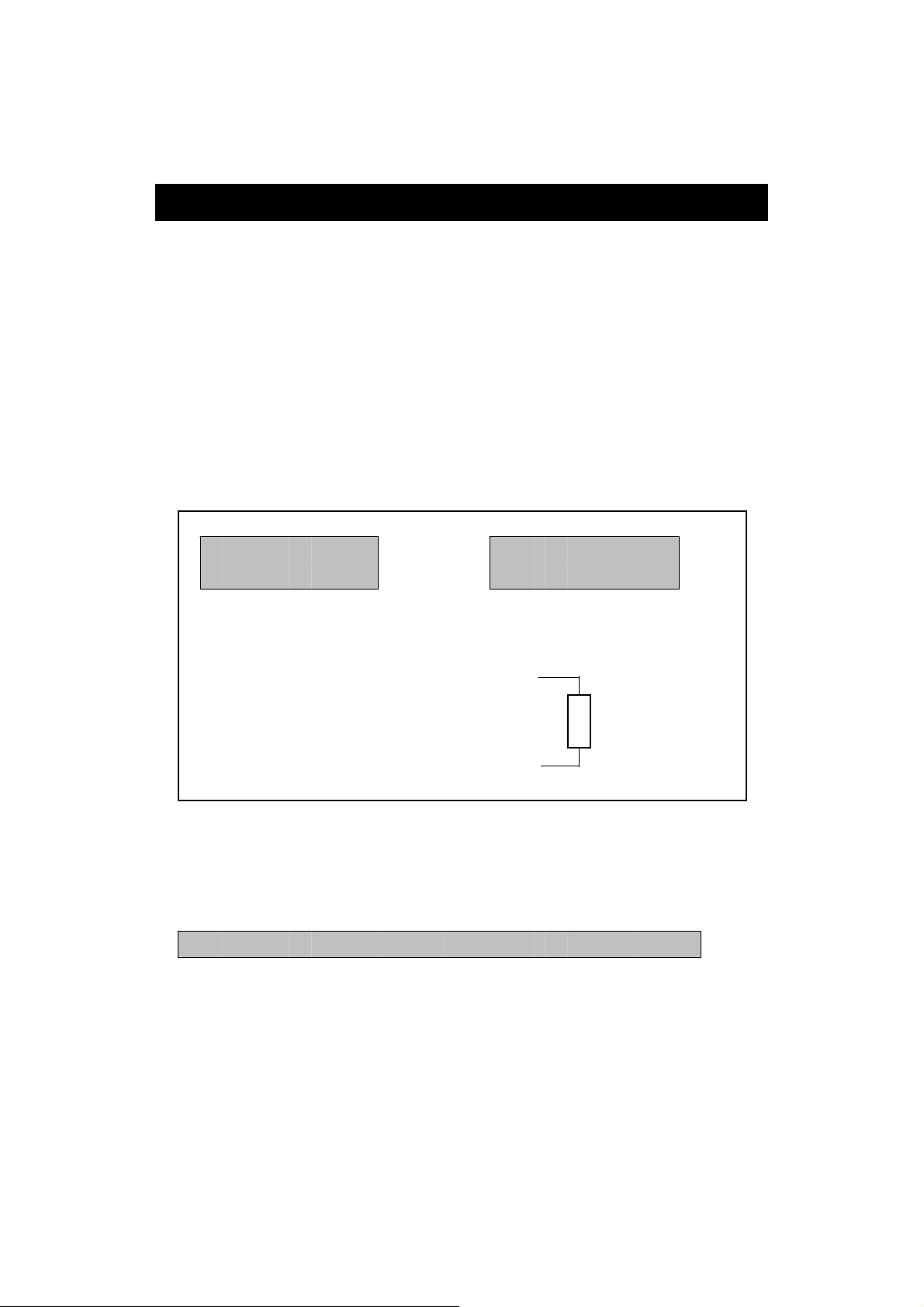
9. RS232 PC SERIAL INTERFACE
.
The instrument has RS232 PC serial interface via a 3.5
mm terminal ( 3-8, Fig. 2 ).
The data output is a 16 digit stream which can be
utilized for user's specific application.
A RS232 lead with the following connection will be
required to link the instrument with the PC serial port.
PC
Meter (9W 'D" Connector)
Center Pin............................................
Pin 4
(3.5 mm jack plug)
Ground/shield......................
Pin 2
2.2 K
resister
Pin 5
The 16 digits data stream will be displayed in the
following format :
D15 D14 D13 D12 D11 D10 D9 D8 D7 D6 D5 D4 D3 D2 D1 D0
17
Page 20
Each digit indicates the following status :
D0 End Word
D1 & D8 Display reading, D1 = LSD, D8 = MSD
For example :
If the display reading is 1234, then D8 to
D1 is : 00001234
D9 Decimal Point(DP), position from right to the
left
0 = No DP, 1= 1 DP, 2 = 2 DP, 3 = 3 DP
D10 Polarity
0 = Positive 1 = Negative
D11 & D12 Annunciator for Display
= 92 = 97
mm/s = 93 cm/s = 95 inch/s = 98
mm = 94 inch = 96 g = 57
D13 When send the upper display data = 1
When send the lower display data = 2
D14 4
D15 Start Word
RS232 setting
Baud rate 9600
Parity No parity
Data bit 8 Data bits
no.
Stop bit 1 Stop bit
18
Page 21

10. BATTERY REPLACEMENT
When the left up corner of LCD show " " indicator,
it is necessary to replace the battery. However,
1)
in-spec measurement may still be made for several
hours after low battery indicator appears before the
instrument become inaccurate.
2)Open the " Battery Cover " ( 3-7, Fig. 2 ) away from
the instrument and remove the battery.
3)Install a 9 V battery ( Alkaline or heavy duty ) and
replace the cover.
11. OPTIONAL ACCESSORIES
RS-232 cable, Interface cable used for connecting the
Model : UPCB-01 vibration meter & the computer ( COM port ).
USB cable, Interface cable used for connecting the
Model : USB-01 vibration meter & the computer ( USB port ).
Data Acquisition After setup whole hardware
software,
SW-801-WIN Vibration meter + RS-232 cable +
Computer + software ( SW-U801-WIN )
whole system can execute as a data logger,
data recorder.... record data can be retrieved
for EXCEL, LOTUS-123.....
Data Logger Vibration meter + RS-232 cable ( or USB cable
( data collection ) ) + Computer + software ( DL-2005 ) It can
software, down load the MEMORY data out from the
DL-2005 meter to the computer.
19
Page 22
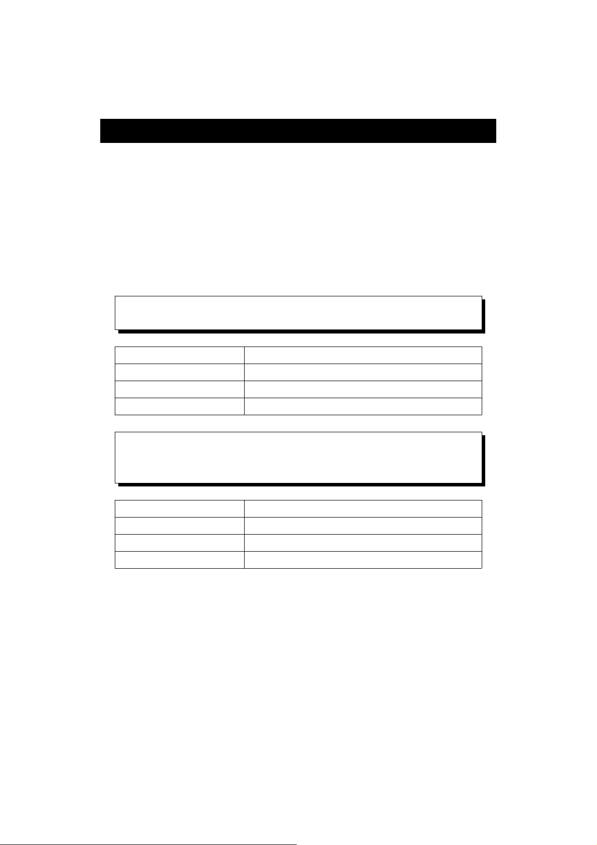
12. CLASSIFICATION RANGES
For the valuation of machines and equipment in the ISO
2372 and VDI 2056, four different kinds of machine groups
with four classification ranges and their limits for vibration
severity ( mm/s ) are determined.
The classifications for each machine group are specified as
follows :
Small machines, especially production electrical
motors of up to 15 KW ( Group K )
Good 0 to 0.71 mm/s
Acceptable 0.72 to 1.80 mm/s
Still permissible 1.81 to 4.5 mm/s
Dangerous > 4.5 mm/s
Medium sized machines, especially electrical
motors with 15 up to 75 KW output, without
special foundations ( Group M )
Good 0 to 1.12 mm/s
Acceptable 1.13 to 2.80 mm/s
Still permissible 2.81 to 7.1 mm/s
Dangerous > 7.1 mm/s
20
Page 23
Large machines on heavy foundations ( Group G )
Good 0 to 1.80 mm/s
Acceptable 1.81 to 4.50 mm/s
Still permissible 4.51 to 11.2 mm/s
Dangerous > 11.2 mm/s
Largest machines and turbo machines with a
special foundations ( Group T ).
Good 0 to 2.80 mm/s
Acceptable 2.81 to 7.10 mm/s
Still permissible 7.11 to 18.0 mm/s
Dangerous > 18 mm/s
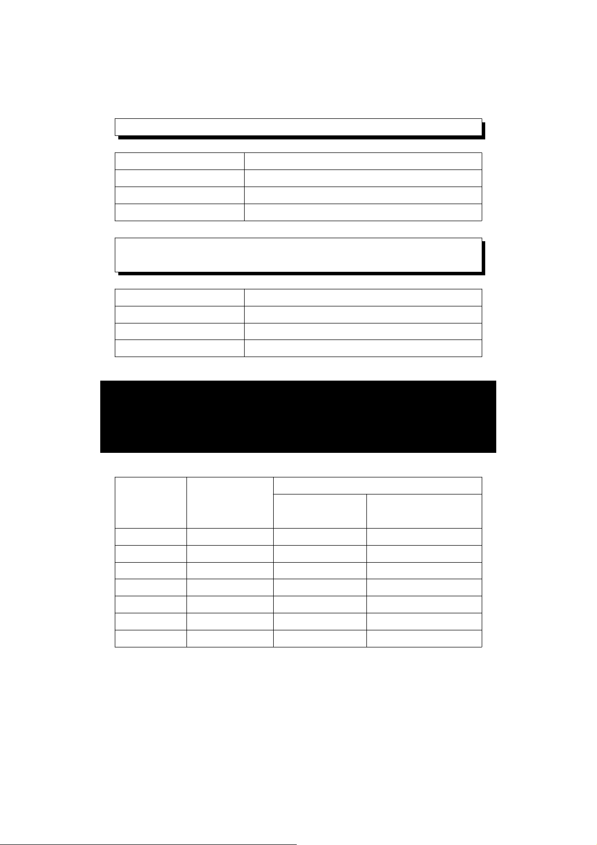
13. SENSITIVITY RELATIVE to the
reference sensitivity at 80 Hz ,
according ISO 2954
Frequency Normal Relative sensitivity
value Minimum Maximum
value value
10 Hz 1.0 0.8 1.1
20Hz Hz 1.0 0.9 1.1
40 Hz 1.0 0.9 1.1
80 Hz 1.0 1.0 1.0
160 Hz 1.0 0.9 1.1
500 Hz 1.0 0.9 1.1
1000 Hz 1.0 0.8 1.1
Table 1
21
0702-VB8213
 Loading...