

Page 1
0.00 to 50.00 NTU, 50 to 1,000 NTU
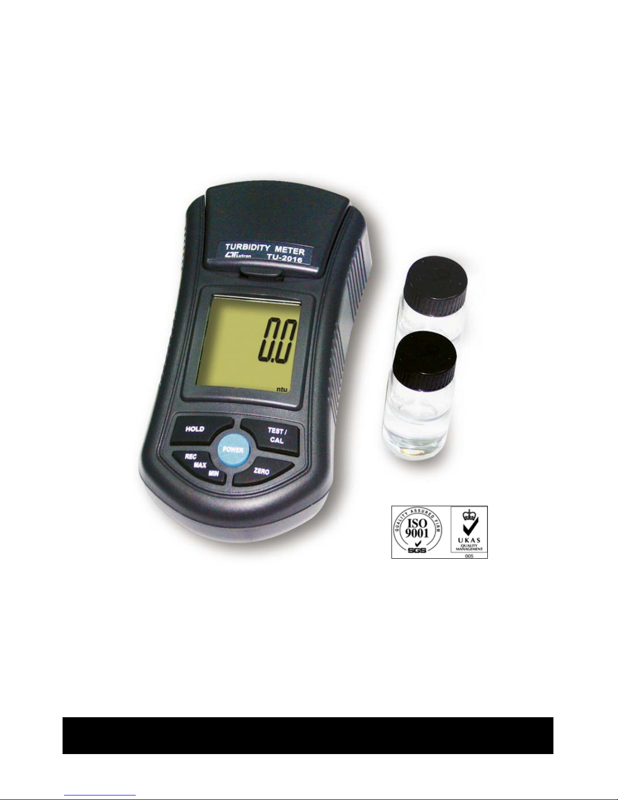
TURBIDITY METER
Model : TU-2016
Your purchase of this TURBIDITY METER marks a step
forward for you into the field of precision measurement.
Although this CHLORINE METER is a complex and delicate
instrument, its durable structure developed. Please read the
following instructions carefully and always keep this manual
within easy reach.
OPERATION MANUAL
Page 2

TABLE OF CONTENTS
1. FEATURES................................................................1
2. SPECIFICATIONS......................................................1
3. FRONT PANEL DESCRIPTION....................................
.
3
3-1 Cover of Testin
g
bottle.........................................3
3-2 Container of Testin
g
bottle...................................3
3-3 Display...............................................................
.
3
3-4 Hold Button ( Esc Button )...................................
.
3
3-5 TEST/CAL Button ( Enter Button )........................
.
3
3-6 Power Button...................................................... 3
3-7 ZERO Button.......................................................3
3-8 REC Button ( MAX, MIN Button )..........................
.
3
3-9 Testing bottle with 0 NTU standard solution........ 3
3-10 Testin
g
bottle with 100 NTU standard solution.....3
3-11 Empty testin
g
bottle 1........................................3
3-12 Empty testin
g
bottle 2........................................3
3-13 Battery Compartment/Cover...............................3
3-14 Clean Cloth.......................................................
.
3
3-15 Clean Solution ( Distill Water )............................3
4. MEASURING PROCEDURE..........................................4
4-1 Measurement Consideration.................................4
4-2 Measurement......................................................5
4-3 Zero...................................................................
.
6
4-4 Data Hold...........................................................
.
6
4-5 Data Record ( Max., Min. readin
g
).......................6
5. CALIBRATION PROCEDURE....................................... 7
6. CALIBRATION CLEAR................................................11
7. BATTERY REPLACEMENT...........................................13
Page 3

1. FEATURES
* Designed to meet ISO 7027.
* NTU ( Nephelometric TURBIDITY Unit ) measuring unit.
* Wide and auto measurement range : 0 to 1,000 NTU.
* High resolution : 0.01 NTU/1 NTU.
* The unique optics structure, enables the instrument to
read low value of TURBIDITY to the high level up to
1,000 NTU.
* Four operation buttons and two calibration points, easy
operation and giarantee the spec. accuracy.
* Jumbo LCD, easy readout.
* Microprocessor circuit assures maximum possible
accuracy, provides special functions and features.
* Battery operated for field and on-site testing convenience.
* Data hold function for freezing the desired value on
display.
* Records Maximum and Minimum readings with Recall.
* Heavy duty & compact housing with hard carrying case,
designed for easy carry out & operation.
* Auto shut off is available to save battery life.
* Application : Test municipal water, food and beverage
water, or other aqueous solution where fluid clarity is
important.
2. SPECIFICATIONS
Circuit Custom one-chip of microprocessor LSI
circuit.
Display LCD size : 41 mm x 34 mm.
Range 0.00 to 50.00 NTU, 50 to 1,000 NTU
* NTU : Nephelometric Turbidity Unit
* Auto range
1
Page 4
Accuracy ± 5 % F.S. or ± 0.5 NTU, which ever is
greater.
Light source LED, 850 nm.
Detector Photo diode
Standard Meet ISO 7027.
Response time Less than 10 seconds.
Sample volume 10 mL.
needed
Data hold Freeze the display reading.
Memory recall Maximum & Minimum value.
Display Approx. 1 second.
sampling time
Power off Auto shut off saves battery life or manual
off by push button.
Calibration 0 NTU, 100 NTU.
points
Operating 0 to 50 .℃
temperature Less than 85% R.H.
and humidity
Power supply DC 1.5 V battery ( UM4, AAA ) x 6 PCs,
or equivalent.
Power current Stand by Approx. DC 3.5 mA.
Testing Approx. DC 36 mA.
Weight 320 g/0.70 LB.
@ Battery is included.
Dimension 155 x 76 x 62 mm ( 6.1 x 3.0 x 2.4 inch)
Accessories Instruction manaual 1 PC.
Included Testin
g
bottle with 0 NTU standard, TU-0NTU.....1 PC.
T
esting bottle with 100 NTU standard, TU-100NTU....
.
1 PC.
Empty testin
g
bottle ( Bottle-061 ).....................2 PCs
Clean cloth.......................................................1 PC.
Clean solution ( Distill water ).......................
.
1 bottle
Hard carryin
g
case, CA-08.................................1 PC.
Optional Testing bottle with 100 NTU standard solution, TU-100NTU
Accessories Testing bottle with 0 NTU standard solution, TU-0NTU
Empty testing bottle, 0601
2
Page 5
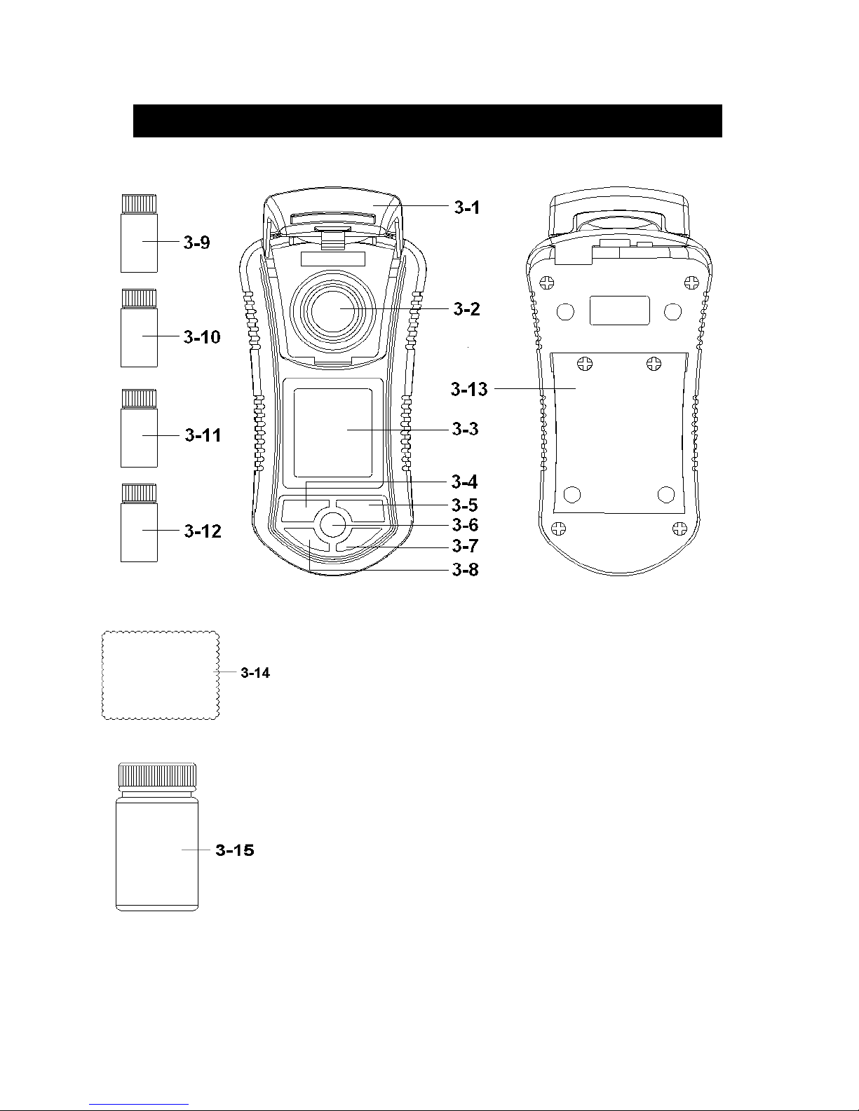
3. FRONT PANEL DESCRIPTION
3-1 Cover of Testing bottle
3-2 Container of Testing bottle
3-3 Display
3-4 Hold Button ( Esc Button )
3-5 TEST/CAL Button
3-6 Power Button
3-7 ZERO Button
3-8 REC Button ( MAX, MIN Button )
3-9 Testing bottle with 0 NTU standard solution
3-10 Testing bottle with 100 NTU standard solution
3-11 Empty testing bottle 1
3-12 Empty testing bottle 2
3-13 Battery Compartment/Cover
3-14 Clean Cloth
3-15 Clean Solution ( Distill Water )
3
Page 6

4. MEASURING PROCEDURE
4-1 Measurement Consideration
White mark
on the up
position of
" Testing
Bottle "
White mark
on the edge of the " Container "
Fig. 2
1)There is a " White mark " on the edge of the
" Container " ( 3-2, Fig. 1 ) and also on the up
position of " Testing Bottle " ( 3-9, 3-10, 3-11,
3-12, Fig. 1 ), refer Fig. 2.
2)
When make the
measurement ( or
calibration ), it should
keep the " Container
white mark " face to face
together with the
" Testing bottle white mark "
4
Page 7

3)Insert the " Testing bottle " to the bottom of
" Container " ( 3-2, Fi
g
. 1 ) completely.
4)Before the measurement, it should envelop in the
" Cover " ( 3-1, Fig. 1 ) completely.
Remark : Before the measurement, it should
keep the outside of Testing Bottle
under the dry condition and withou
t
existing any dust.
4-2 Measurement
1)Fill the measurement liquid into the " Testing bottle "
( 3-11, 3-12, Fig. 1 ) .
Attention :
Model 0601
It should fill th
e
10 mL
measuremen
t
liquid capacit
y
until its leve
l
up to the " leve
l
marker " of the
" Testing bottle
"
2)Insert the " Testing bottle " to the bottom of
" Container " ( 3-2, Fig. 1 ) completely.
3)Before the measurement, it should envelop in the
" Cover " ( 3-1, Fig. 1 ) completely.
4)Power ON the meter by pressing the " Power Button "
( 3-6, Fig. 1 ) once.
5)Press " TEST Button " ( 3-5, Fig. 1 ) once, the display
will show the text " tESt " ( TEST )", following the "
tESt " will flash approx. 10 seconds , then the TURBIDITY
value will present on the display along with the " ntu "
unit.
5
Page 8

Remark :
* Under power OFF, if press the TEST Button " ( 3-5,
Fig. 1 ) will power ON and going on to make the test
automatically.
* After the testing, within ten minutes approx., the
meter will auto power OFF automatically.
Wash ( Reinse ) the Testing bottle
* After the testing, it should wash ( reinse )
the Testing Bottle by the Clean Solution
( Distill Water ) " ( 3-17, Fig. 1 ).
4-3 Zero
When measure the " 0 NTU " liquid, if the display not show
the zero value, it can deduct ( offset ) those " not zero
value " with default, the zero procedures are :
Press the " ZERO Button " ( 3-7, Fig, 1 ) continuously
until the display show zero value then release the
finger from the button
* Remark :
The zero function can be executed within
the zero dift value < 2.0 NTU only.
4-4 Data Hold
During the measurement, press the " Hold Button " ( 3-4,
Fig. 1 ) once will hold the measured value & the LCD will
display a " HOLD " symbol.
* Press the " Hold Button " once again will release the data
hold function.
4-5 Data Record ( Max., Min. reading )
* The data record function records the maximum and
minimum readings. Press the " REC Button " ( 3-8, Fig.
1 ) once to start the Data Record function and there
will be a " REC. " symbol on the display.
6
Page 9

* With the " REC. " symbol on the display :
a)Press the " REC Button " ( 3-8, Fig. 1 ) once, the "
REC. MAX. " symbol along with the maximum value
will appear on the display.
If intend to delete the maximum value, just press
the " Hold Button " ( 3-4, Fig. 1 ) once, then the
display will show the " REC. " symbol only & execute
the memory function continuously.
b)Press the " REC Button " ( 3-8, Fig. 1 ) again, the
" REC. MIN. " symbol along with the minimum value
will appear on the display.
If intend to delete the minimum value, just press
the " Hold Button " ( 3-4, Fig. 1 ) once, then
the display will show the " REC. " symbol only &
execute the memory function continuously.
5. CALIBRATION PROCEDURE
1)The meter can be calibrated under two kinds standard
solution :
0 NTU standard solution
100 NTU standard solution
2)The meter ship along with
a. Testing bottle with 0 NTU standard solution x 1 PC
b. Testing bottle with 100 NTU standard solution x 1 PC
as the standard accessories.
3)The complete calibration should be executed by
following two solution :
0 NTU standard solution
100 NTU standard solution
7
Page 10

4) Shaking the calibration bottle lightly
Before execute the calibration, it should shake
lightly ( not strongly ) the
Standard solution ( TU-0NTU, TU-100NTU )
one to two seconds to let the calibration
solution under the uniform condition.
Remark :
Do not shake the Standard solution strongly due to it may
generate the " Air bubble " and let the solution existing not
accurate value.
5) The buttons that will be used during
the Calibration procedures
Escape button, select button :
Fig. 1, 3-4 Hold Button ( Esc Button )
Calibration button, Enter button :
Fig. 1, 3-5 TEST/CAL Button ( Enter Button )
6) 0 NTU calibration
a.Insert the " 0 NTU standard solution into the
" Container " ( 3-2 , Fig. 1) and envelope in the " Cover "
( 3-1, Fig. 1 ) completely, other procedures please
refer to above section 4-1, 4-2.
8
Page 11

b.Press " CAL Button " ( 3-5, Fig. 1 ) continuously
(at least 3 seconds ) until the Display show the text
" CAL " then release the button.
CAL Fig. 5-1
ntu
c. After the LCD show above Fig. 5-1, wait a while
the display will show
0.00
CAL ntu
Now the meter is ready for the " 0 NTU " calibration
d.Press " CAL Button " ( 3-5, Fig. 1 ) once, the
Display will show following text with flashing ( approx.
10 seconds ).
flashing
CAL
0.0 ntu
9
Page 12

Then the Display will show :
100
CAL ntu
Now the meter is finished the " 0 NTU " calibration
procedures and ready for " 100 NTU " calibration
procedures.
7) 100 NTU calibration
When finish the " 0 NTU " calibration procedures and
the Display show :
100
CAL ntu
The meter is ready for " 100 NTU " calibration.
* Insert the " 100 NTU standard solution into the
" Container " ( 3-2 , Fig. 1) and envelope in the " Cover "
( 3-1, Fig. 1 ) completely.
Press " CAL Button " ( 3-5, Fig. 1 ) once, the
Display will show following text with flashing ( approx.
10 seconds ).
flashing
CAL
100 ntu
10
Page 13

Then the LCD display will return to normal
measurement screen, now the meter is finished the
calibration procedures ( 0 NTU, 100 NTU calibration )
completely and ready for the measurement.
8)
During the calibration, if exit something wrong
( Error, can not be calibrated....... ), please check
if the " Standard solution " value is wrong, if
still can not fix the problem , then execute the
execute the " Calibration clear " procedures
( Section 6 ) may can fix the problem.
6. CALIBRATION CLEAR
Execute the calibration procedures will clear all the
calibration value ( Section 5 ) , the system will
return to the Default value.
a.Power On ( no matter if the " Testing bottle " insert
into the " Container " or not ) press the " CAL Button "
( 3-5, Fig. 1 ) continuously (at least 3 seconds ) until
the Display show the text " CAL " then release the
button, the display will show :
CAL Fig. 6-1
ntu
b.After the LCD show above Fig. 6-1, wait a while
the display will show :
0.00
CAL ntu
11
Page 14

Press " Hold Button " ( 3-4, Fig. 1 ) once the display
will show :
100
CAL ntu
Press " Hold Button " ( 3-4, Fig. 1 ) once again
the display will show :
CLr Now the meter is ready for
CAL ntu the " Calibration clear "
Press " CAL Button " ( 3-5, Fig. 1 ) once, the
Display will show following text with flashing ( approx.
10 seconds ).
flashing
CAL
CLr
Then the LCD display will return to normal
measurement screen, now the meter is finished the
calibration clear procedures and clear all the existing
calibration data.
12
Page 15

7. BATTERY REPLACEMENT
1)When the left corner of LCD display show " ", it
is necessary to replace the battery. However, in-spec.
measurement may still be made for several hours after
low battery indicator appears before the instrument
become inaccurate.
2)Loss the " Battery Cover Screws " and slide the
" Battery Cover " ( 3-13, Fig. 1 ) away from the
instrument and remove the battery.
3)Replace with DC 1.5 V battery ( UM4, AAA,
Alkaline/heavy duty ) x 6 PCs, and reinstate the cover.
4)Make sure the battery cover is secured after changing
the battery.
13
0812-TU2016
 Loading...