

Page 1
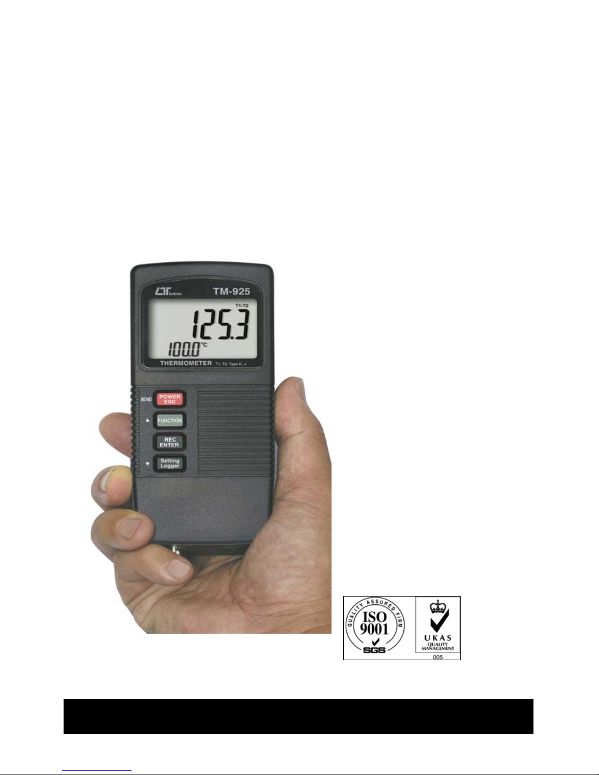
T1, T2, T1-T2, Type K/J
TWO CHANNEL
THERMOMETE
R
Model : TM-925
Your purchase of this
T
HERMOMETER marks a
step forward for you
into the field of
precision measurement.
Althou
g
h this
T
HERMOMETER is a
complex and delicate
instrument, its durable
structure will allow
many years of use if
proper operatin
g
techniques are
developed. Please read
the followin
g
instructions carefully
and always keep this
manual within easy
reach.
OPERATION MANUAL
Page 2

TABLE OF CONTENTS
1. FEATURES..............................................................1
2. SPECIFICATIONS.................................................... 1
3. FRONT PANEL DESCRIPTION..................................
.
5
3-1 Display...........................................................................5
3-2 Power/ESC/Send button.................................................. 5
3-3 Function/Hold button ( Send quit/ button )..................
.
▲ 5
3-4 REC/Enter button...........................................................
.
5
3-5 Settin
g
/Logger button ( button ).................................
.
▼ 5
3-6 T1 probe socket.............................................................
.
5
3-7 T2 probe socket.............................................................
.
5
3-8 DC 9V adapter socket.....................................................
.
5
3-9 RS-232 output terminal................................................... 5
3-10 Battery compartment/Cover............................................5
4. GENERAL MEASURING PROCEDURE...........................6
4-1 One probe ( sin
g
le channel ) measurement.........................6
4-2 Two probes ( dual channels ) measurement.......................
.
7
4-3 Data Hold.........................................................................8
4-4 Data Record (Max, Min readin
g
).........................................8
4-5 Data Lo
gg
er......................................................................9
5. ADVANCED MEASURING PROCEDURE........................11
5-1 Chan
g
e the type K. J.........................................................12
5-2 Chan
g
e the Temp , unit.............................................℃℉ 12
5-3 Auto power ON/OFF..........................................................12
5-4 Chan
g
e the data logger sampling time................................12
5-5 To show the balance data numbers in the memory.............
.
13
5-6 Clear the existin
g
saving data from the memory..................13
6. HOW TO SEND THE DATA OUT FROM THE METER.....
.
14
7. RS232 PC SERIAL INTERFACE...................................
.
15
8. BATTERY REPLACEMENT...........................................17
9. OPTIONAL ACCESSORIES..........................................17
Page 3
1. FEATURES
* Two channels thermometer, T1, T2, T1-T2, T1 only.
* Both type K/J temp. measurement, wide range.
* / , 0.1 degree.℃℉
* Microcomputer circuit provides intelligent function
and high accuracy.
* LCD with two display, easy readout.
* Manual and auto data logger, with flexible sampling
time selection, can save max. 1,600 reading data.
* Records Maximum and Minimum readings with recall.
* Data hold function for freezing the desired value.
* Meter can default to accept type K or type J Temp. probe.
* Meter can default auto power off or manual power off.
* Meter can default the measuring unit to or .℃℉
* Build in the input socket for DC 9V power adapter.
* RS232 PC serial interface.
* Few panel buttons, easy operation.
* Built-in low battery indicator.
* Heavy duty & compact housing case.
2. SPECIFICATIONS
2-1 General Specifications
Circuit Custom one-chip of microprocessor LSI
circuit.
Display LCD size : 44 mm x 29 mm
dual function LCD display.
1
Page 4
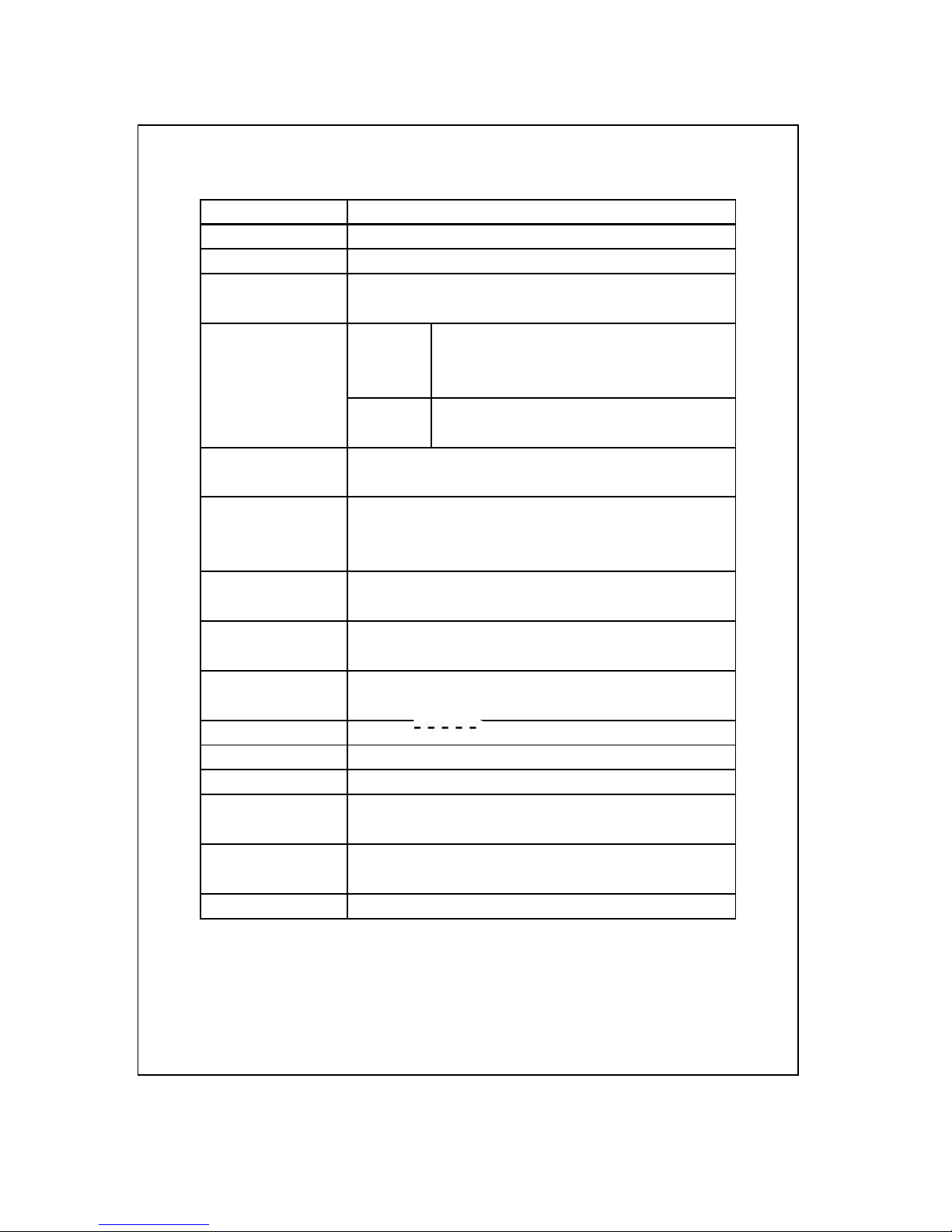
Display Unit , .℃℉
Resolution 0.1 , 0.1 .℃℉
Channels T1, T2, T1-T2, T1 only.
Thermocouple Type K or Type J.
type
Sampling Time Manual Push the data logger button
of Data Logger once will save data one time.
* Se the sampling to 0 second.
Auto 1, 2, 5, 10, 30, 60, 600, 1800,
3600 seconds.
Data Logger Max. 1,600-point Data logger
number
Temperature Automatic temp. compensation for the
Compensation cold junction both type K/J thermometer
Linear Linear Compensation for the full range.
Compensation
Offset, Span Available for advanced calibration
Adjustment procedure.
Probe Input Standard 2 pin thermocouple socket.
Socket
Over Indication
Show " ".
Data Hold Freeze the display reading.
Memory Recall Maximum & Minimum value.
Sampling Time Approx. 1 second.
of display
Power off Auto shut off saves battery life or
manual off by push button.
Data Output RS 232 PC serial interface.
2
Page 5

Operating 0 to 50 .℃
Temperature
Operating Less than 80% R.H.
Humidity
Power Supply 006P DC 9V battery
( Alkaline or Heavy duty type ).
DC 9V adapter input.
* AC/DC power adapter is optional.
Power Current Approx. DC 5.5 mA
Weight 196 g/0.43 LB.
Dimension 135x60x33 mm, ( 5.3x2.4x1.3 inch ).
Accessories Instruction manual..................1 PC
Included
Optional * Type K thermocouple probe.
Accessories TP-01, TP-02A. TP-03, TP-04
* AC to DC 9V adapter.
* RS232 cable, UPCB-02.
*USB cable, USB-01
* Data Acquisition software,
SW-U801-WIN.
* Data Logger software, SW-DL2005.
* Carrying case, CA-52A.
3
Page 6
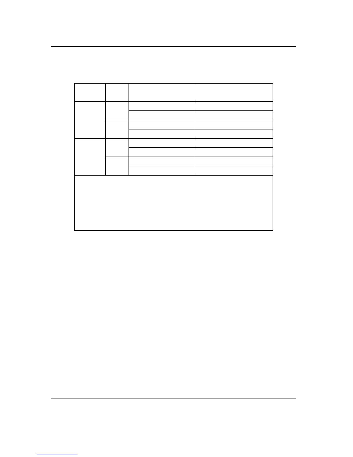
2-2 Electrical Specifications (23±5 )℃
Sensor Reso- Range Accuracy
Type lution
Type K 0.1 ℃ -50.0 to 1300.0 ℃ ± ( 0.4 % + 0.8 )℃
-50.1 to -199.9 ℃ ± ( 0.4 % + 1 )℃
0.1 ℉ -58.0 to 2372.0 ℉ ± ( 0.4 % + 1.5 )℉
-58.1 to -327.8 ℉ ± ( 0.4 % + 1.8 )℉
Type J 0.1 ℃ -100.0 to 1100.0 ℃ ± ( 0.4 % + 0.8 )℃
-50.1 to -199.9 ℃ ± ( 0.4 % + 1 )℃
0.1 ℉ -58.0 to 2012.0 ℉ ± ( 0.4 % + 1.5 )℉
-58.1 to -327.8 ℉ ± ( 0.4 % + 1.8 )℉
*
Accuracy value is specified for the meter only.
*
Type K probe TP-01 TP-02A, TP-03. TP-04 is the
optional accessory, refer page
*
Above specification tests under the environment RF
Field Strength less than 3 V/M & frequency less than
30 MHz only.
4
Page 7

3. FRONT PANEL DESCRIPTION
Fig. 1
3-1 Display
3-2 Power/ESC/Send button
3-3 Function/Hold button ( Send quit/ button )▲
3-4 REC/Enter button
3-5 Setting/Logger button ( button )▼
3-6 T1 probe socket
3-7 T2 probe socket
3-8 DC 9V adapter socket
3-9 RS-232 output terminal
3-10 Battery compartment/Cover
5
Page 8

4. GENERAL MEASURING
PROCEDURE
Meter defaults :
*The temperature reading unit is .℃
*Type K measurement
*Auto power off.
*The sampling time of data logger function is
2 seconds.
4-1 one probe ( single channel ) measurement
1)Insert the " Temp. probe plug " into the " T1 probe
socket " 3-6, Fig. 1 ).
2)Power on the meter by pressing the " Power button "
( 3-2, Fig. 1 ) once a while.
3)Press the " Function button " ( 3-3, Fig. 1 ) continuously
until the LCD show the " T1- " symbol, release the
finger from the button the display will show the
temperature reading that sensing from the probe's head.
T1-
K
26.3
℃
6
Page 9

4-2 two probes ( dual channels ) measurement
1)For two probes ( dual channels ) measurement, insert
the first " Temp. probe plug " into the " T1 probe socket "
( 3-6, Fig. 1 ) and insert the second " Temp. probe
plug " into the " T2 probe socket " ( 3-7, Fig. 1 ).
2)Power on the meter by pressing the " Power Button "
( 3-2, Fig. 1 ) once a while.
3)Press the " Function button " ( 3-3, Fig. 1 )
continuously until the LCD show the " T1 " symbol
then release the finger from the button, the upper
display will show the T1 temperature reading, the
lower display will show the T2 temperature reading.
T1
K
28.6 T1 temperature
℃
27.4 T2 temperature
4)Press the " Function button " ( 3-3, Fig. 1 )
continuously until the LCD show the " T2 " symbol
then release the finger from the button, the upper
display will show the T2 temperature reading, the
lower display will show the T1 temperature reading.
T2
K
27.4 T2 temperature
℃
28.6 T1 temperature
7
Page 10

4)Press the " Function button " ( 3-3, Fig. 1 )
continuously until the LCD show the " T1-T2 " symbol
then release the finger from the button, the upper
display will show the T1-T2 temperature reading, the
lower display will show the T1 temperature reading.
T1-T2
K
1.2 T1-T2 temperature
℃
28.6 T1 temperature
Note :
1) If intend to change the measuring unit from to , ℃℉
refer section 5-2, page 12.
2) If intend to change the measuring function from type K to type J,
refer section 5-1, page 12.
4-3 Data Hold
During the measurement, press the " Hold Button " ( 3-3,
Fig. 1 ) once will hold the measured value & the LCD will
display a " HOLD " symbol.
* Press the " Hold Button " once again will release the data
hold function.
4-4 Data Record ( Max., Min. reading )
* The data record function records the maximum and
minimum readings. Press the " REC Button " ( 3-4, Fig.
1 ) once to start the Data Record function and there
will be a " REC " symbol on the display.
8
Page 11

* With the " REC " symbol on the display :
a)Press the " REC Button " ( 3-4, Fig. 1 ) once, the
" REC MAX " symbol along with the maximum value
will appear on the display.
If intend to delete the maximum value, just press
the " Hold button " ( 3-3, Fig. 1 ) once, the display
will show the " REC " symbol only & execute the
memory function continuously.
b)Press the " REC button " ( 3-4, Fig. 1 ) again, the
" REC. MIN. " symbol along with the minimum value
will appear on the display.
If intend to delete the minimum value, just press
the " Hold button " ( 3-3, Fig. 1 ) once, then
the display will show the " REC " symbol only &
execute the memory function continuously.
c)To exit the memory record function, just press the
" REC " button for 2 seconds at least. The display will
revert to the current reading.
4-5 Data Logger
The data logger function can save 1,600 measuring
data.
The data logger procedures are as following :
a)Press the " REC Button " ( 3-4, Fig. 1 ) once to
start the Data Record function and there will be a
" REC " symbol on the display.
9
Page 12

b)Auto Data Logger ( Sampling time should select
to 1, 2, 5, 10, 30, 60, 600, 1800 or 3600 seconds )
Press the " Logger button " ( 3-5, Fig. 1 ) once to start
the Data Logger function. The REC symbol will flash
per sample time period and save the data into the
memory. Now the Date Logger function is executed.
Manual Data Logger ( Sampling time should set
to 0 second )
Press the " Logger Button " ( 3-6, Fig. 1 ) once will
save the data one time into the memory, at the
same time the symbol " REC " will flash once a while.
Memory full
When execute the data logger function, if the upper
display show " FULL " with flashing, it indicate the
memory data already over 1,600 no. and the
memory is full.
c)During the Data Logger function is executed, press the
" Logger Button " ( 3-5, Fig. 1 ) once will stop the
data logger function, the " REC " symbol will stop to
flash.
If press the " Logger Button " ( 3-5, Fig. 1 ) once again
will continuous the Data Logger function.
10
Page 13

Note :
1) If intend to change the data logger sampling time, please
refer section 5-4, page 12.
2) If intend to know the space of balance data numbers into the
memory IC, please refer section 5-5, page 13.
3) If intend to clear the saving data from the memory please
refer section 5-6, page 13.
5. ADVANCED SETTING
PROCEDURE
Before executing advanced adjustment
procedures, exit the " Hold function " and the
Record " function.
a.Hold the " Setting Button " ( 3-5, Fig. 1 ) at least five
seconds will enter the Advanced Setting
Procedures.
b.One by one to press the " Setting Button " ( 3-5, Fig. 1 )
once a while to select the seven main function and show
the text the lower display as :
K..........
.
Change thermocouple type to type K or type J
.........
.
℃ Change the Temp , unit℃℉
OFF......
.
Auto power ON/OFF management
SP-t......Change the data logger sampling time
SPACE..
.
To show the balance data numbers in the memory
CLr.......
.
Clear the existing saving data from the memory
Code....
.
Code entering for the further calibration usage
11
Page 14

5-1 Change thermocouple type to type K or type J
a.Use " button " ( 3-3, Fig. 1 ) to select " K " or " J ".▲
b.After select the desiring value ( K or J ), press the
" Enter button " ( 3-4, Fig. 1 ) to save the data with
default.
5-2 Change the Temp , unit℃℉
a.Use " button " ( 3-3, Fig. 1 ) to select " " or " ".▲℃℉
b.After select the desiring value ( or ), press the ℃℉
" Enter button " ( 3-4, Fig. 1 ) to save the data with
default.
5-3 Auto power On/Off
( Lower display show " OFF " )
a.Use " button " ( 3-3, Fig. 1 ) to select " YES " or " no ".▲
* YES : Auto power off.
* no : Auto power disable,
b.After select the desiring function ( YES or no ), press the
" Enter button " ( 3-4, Fig. 1 ) to save the function with
default.
5-4 Change the data logger sampling time
( Lower display show " SP-t " )
a.Use " button " ( 3-3, Fig. 1 ) to select ▲
data logger sampling time to
0, 1, 2, 5, 10, 30, 60, 600, 1800, 3600 seconds
b.After the sampling time value is determined, press the
Enter button " ( 3-4, Fig. 1 ) to save the sampling
time with default.
Note :
Set the sampling time to 0 second is used
for the manual Data Logger function.
12
Page 15

5-5 To show the balance data numbers in the memory
( Lower display show " SPACE " )
The display will show the balance data no. that exist
into the memory ( allow memorize data no. ).
5-6 Clear the existing saving data from the memory
( Lower display show " CLr " )
a.Use " button " ( 3-3, Fig. 1 ) to select " YES " or " no ".▲
* YES : It will execute the memory clear function..
* no : It will be not to clear the memory.
b.If select " YES ", press the " Enter button " ( 3-4, Fig. 1 )
again will clear the memory exactly.
5-7 Code entering for the further calibration usage
( Lower display show " CodE" )
The upper display will show 100.
The code setting is used for the further calibration usage.
It do not enter any new code, just press the " Enter button
" ( 3-4, Fig. 1 ) will finish the Advanced Setting Procedure.
13
Page 16

6. HOW TO SEND THE DATA OUT
1)To send the data out from the meter, cancel the
" Hold function " and the " Record function " first.
2)Press the " Send Button " ( 3-2, Fig. 1 ) at least 5
seconds until the lower display show " r232 ", then
release the button.
108 The total data logger
no. that saved into
r232 the memory.
3)Push the " Send Button " ( 3-2, Fig. 1 ) once, the lower
display will show " SEnd ", the upper no. will count up
until reach the data logger storage no., at the same
the storage data logger data will send out the meter
from the " RS-232 output terminal " ( 3-9, Fig. 1 ).
0 Count up from 0 to
the data logger
SEnd storage no.
4)If intend up load the data to the computer, then
should connect the optional RS232 cable/UPCB-01 or
USB cable/USB-01 and cooperate the Data Logger
software ( optional, Model : SW-DL2005 ).
5)Press the " Send quit button " ( 3-3, Fig. 1 ) will
escape the data sending function.
14
Page 17

7. RS232 PC SERIAL INTERFACE
The instrument has RS232 PC serial interface via a 3.5
mm terminal ( 3-9, Fig. 1 ).
The data output is a 16 digit stream which can be
utilized for user's specific application.
A RS232 lead with the following connection will be
required to link the instrument with the PC serial port.
Meter PC
(3.5 mm jack plug) (9W 'D" Connector)
Center Pin...............................Pin 4
Ground/shield........................Pin 2
Pin 5
The 16 digits data stream will be displayed in the
following format :
D15 D14 D13 D12 D11 D10 D9 D8 D7 D6 D5 D4 D3 D2 D1 D0
15
Page 18

Each digit indicates the following status :
D15 Start Word
D14 4
D13 When send the upper display data = 1
When send the lower display data = 2
D12 & D11 Annunciator for Display
= 01 ℃ = 02℉
D10 Polarity
0 = Positive 1 = Negative
D9 Decimal Point(DP), position from right to the
left
0 = No DP, 1= 1 DP, 2 = 2 DP, 3 = 3 DP
D8 to D1 Display reading, D8 = MSD, D1 = LSD.
For example :
If the display reading is 1234, then D8 to
D1 is : 00001234
D0 End Word
RS232 setting
Baud rate 9600
Parity No parity
Data bit no. 8 Data bits
Stop bit 1 Stop bit
16
Page 19

8. BATTERY REPLACEMENT
1)When the left corner of LCD display show " ", it
is necessary to replace the battery. However, in-spec.
measurement may still be made for several hours after
low battery indicator appears before the instrument
become inaccurate.
2)Slide the " Battery Cover " ( 3-10, Fig. 1 ) away from the
instrument and remove the battery.
3)Replace with 9V battery ( Alkaline or Heavy duty type )
and reinstate the cover.
4)Make sure the battery cover is secured after changing
the battery.
9. OPTIONAL ACCESSORIES
RS232 cable * Isolated RS232 cable.
UPCB-02 * Used to connect the meter to
the computer
RS232 cable * USB Computer interface cable.
USB-01 * Isolated USB cable.
Data Logger * Software the used to download
software the data logger ( data recorder )
SW-DL2005 from the meter to computer.
17
Page 20

Data Acquisition * The SW-U801-WIN is a multi
software displays ( 1/2/4/6/8 displays )
SW-U801-WIN powerful application software,
provides the functions of data
logging system, text display,
angular display, chart display,
data recorder high/low limit, data
query, text report, chart report..
.xxx.mdb data file can be
retrieved for EXCEL, ACESS..,
wide intelligent applications.
(Type K) TP-01 * Max. short-tern operating
Temperature: 300 (572 ).℃℉
* It is an ultra fast response
naked-bead thermocouple
suitable for many general purpose
application.
Thermocouple * Measure Range: -50 to 900 ,℃℃
Probe -50 to 1650 .℉℉
(Type K), TP-02A * Dimension:10cm tube, 3.2mm Dia.
Thermocouple * Measure Range: -50 to 1200 ,℃℃
Probe -50 to 2200 .℉℉
(Type K), TP-03 * Dimension: 10cm tube, 8mm Dia.
Surface Probe * Measure Range: -50 to 400 ,℃℃
(Type K), TP-04 -50 to 752 .℉℉
* Size :
Temp. sensing head - 15 mm Dia.
Probe length - 120 mm.
18
0602-TM925
 Loading...