

Page 1
RS-232
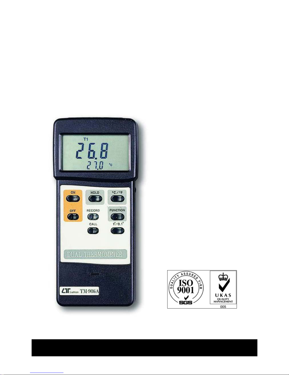
DUAL
THERMOMETE
R
Model : TM-906A
Your purchase of this
DUAL THERMOMETER
marks a step forward for
you into the field of
precision measurement.
Although this
T
HERMOMETER is a
complex and delicate
instrument, its durable
structure will allow many
years of use if proper
operating techniques are
developed. Please read
the following instructions
carefully and always keep
this manual within easy
reach.
OPERATION MANUAL
Page 2

TABLE OF CONTENTS
1. FEATURES.................................................................... 1
2. SPECIFICATIONS.........................................................
.
2
2-1 General Specifications.............................................2
2-2 Electrical Specifications........................................... 3
3. FRONT PANEL DESCRIPTION........................................ 4
3-1 Display...............................................................
.
4
3-2 Power On button.................................................4
3-3 Data Hold Button................................................
.
4
3-4 蚓/ 蚌 button...................................................... 4
3-5 Power Off button................................................
.
4
3-6 Memory "Record" Button.....................................
.
4
3-7 Memory "Call" Button..........................................
.
4
3-8 Function Button(T1, T2, T1-T2)...........................
.
4
3-9 10.1Button..........................................................4
3-10 Battery Compartment/Cover.................................4
3-11 T1 Input Socket..................................................
.
4
3-12 T2 Input Socket..................................................
.
4
3-13 RS-232 Output Terminal......................................
.
4
4. MEASURING PROCEDURE............................................. 5
5. MEASURING CONSIDERATION...................................... 7
6. RS232 PC INTERFACE..................................................
.
8
7. BATTERY REPLACEMENT.............................................. 9
8. OPTIONAL TEMPERATURE PROBE &
& OTHER ACCESSORIES..............................................
.
10
Page 3

1. FEATURES
* Microprocessor circuit assures high accuracy and provides
special functions and features.
* Super large LCD display, easy reading.
* Dual function meter's display.
* Heavy duty & compact housing case.
* Records Maximum, Minimum readings with RECALL.
* Data hold.
* Operates from OO6P DC 9V battery.
* RS 232 PC serial interface.
* Multi functions, dual channel temp. input, differential
temp. measurement, 蚓/蚌, 0.11degree, data hold.
* Meet any standard type K(NiCr-NiAl) probe.
* Fitted with standard type K input measuring socket.
* Build in temperature linearity compensation circuit,
high accuracy and wide measurement.
* Build in precision cold junction compensation circuit.
* Thermocouple sensor for Temp. measurement, fast
response time.
* Used the durable, long-lasting components, including a
strong, light weight ABS-plastic housing case.
* Wide applications: use this anemometer to check air
conditioning & heating systems, measure air velocities,
wind speeds, temperature...etc.
1
Page 4

2. SPECIFICATIONS
2-1 General Specifications
Circuit Custom one-chip of microprocessor LSI
with thermocouple linearity correction
circuit.
Display Dual function meter's display, 13 mm(0.5"),
Super large LCD display with annuciator.
Measurement Two channel temp. input (T1, T2),
differential temp. measurement(T1 -T2),
蚓/蚌, 0.11degree.
Measurement - 50蚓 to 1230蚓/ - 58蚌 to 1999蚌.
Range
Polarity Automatic switching,
'-' indicates negative polarity.
Sensor Thermocouple K(NiCr-NiAl).
Type
Input 10 Meg ohm.
Impedance
Sampling Time Approx. 3 seconds.
Memory Records Maximum, Minimum readings
Recall with RECALL.
Data Output RS 232 PC serial interface.
Over input Indication of "- - - -".
indication
Operating 0 蚓 to 50 蚓(32 蚌 to 122 蚌).
Temperature
Operating Max. 80% RH.
Humidity
2
Page 5

Power Supply 006P DC 9V battery(Heavy duty type).
Power Current Approx. DC 6.2 mA.
Weight 275 g/0.61 LB (included batteries & probe)
Size Main instrument:
180 x 72 x 32 mm(7.1 x 2.8 x1.3 inch).
Accessories Instruction Manual .............. 1 PC.
Included
Optional Temperature probe, carrying case.
Accessories (not included, please see ref. page 9)
2-2 Electrical Specifications (23 5 蚓)
T
EMP. RANGE RESOLUTION ACCURACY
蚓
-50 蚓to 0.1 蚓-50 蚓to 199.9
蚓
1230 蚓 1 蚓-50 蚓to 1000
蚓
(0.75% + 1 蚓)
1001 蚓to 1230
蚓
蚌
-58 蚌to 0.1 蚌-50 蚌to 199.9
蚌
(0.75% + 2 蚌)
1999 蚌 1 蚌-50 蚌to 1999
蚌
蚓
T
1 - T2 (0.75% + 1 蚓)
蚌
T
1 - T2 (0.75% + 2 蚌)
* The above accuracy specification applies only to the
instrument itself and allowance must be made for limits of
error permitted in thermocouple.
3
Page 6

3. FRONT PANEL DESCRIPTION
Fig. 1
3-1 Display 3-8 Function Button
3-2 Power On button (T1, T2, T1-T2)
3-3 Data Hold Button 3-9 10.1Button
3-4 蚓/ 蚌 button 3-10 Battery Compartment
3-5 Power Off button /Cover
3-6 Memory "Record" 3-11 T1 Input Socket
Button 3-12 T2 Input Socket
3-7 Memory "Call" Button 3-13 RS-232 Output
Terminal
4
Page 7

4. MEASURING PROCEDURE
4-1 Temperature Measurement
(1) Push the "Power Off Button"(3-2, Fig. 1) to let the
instrument power "ON".
The instrument has built-in "Auto Power Shut-off" in order to
prolong battery life. To eliminate the " Auto power off "
function, select the memory record function during
measurement, by pressing the " RECORD " button (3-6, fig.1).
(2) Determine temperature unit to 蚓 or 蚌 by push the
"蚓/ 蚌 push button"(3-4, Fig. 1) Then the display
will show the temperature unit of "蚓" or "蚌".
(3) Determine the display resolution to 0.1or 1by push
10.1Button(3-9, Fig. 1)
(4) One probe measurement:
Insert one temp. probe plug into the socket T1(3-11),
then push the "Function Button"(3-8, Fig. 1) until the
display show the marker "T1" Display will show the
temperature reading that measured from the probe.
(5) Two probe(dual channel) & differential measurement:
a. Insert first temp. probe plug into the "T1 Socket"
(3-11, Fig. 1).
b. Insert second temp. probe plug into the "T2 Socket"
(3-12, Fig. 1).
c. The main display(upper display) will show the
temperature reading of first probe(T1) & the lower
display will show the temperature reading of second
probe(T2), if push the "Function Button"(3-8, Fig.
1) until the display show the marker "T1".
d. The main display(upper display) will show the
temperature reading of second probe(T2) & the
lower display will show the temperature reading of
first probe(T1), if push the "Function Button"(3-8,
Fig. 1) until the display show the marker "T2".
5
Page 8

e. The main display(upper display) will show the
differential temperature reading of the first &
second probe(T1 - T2) & the lower display will
show the temperature reading of first probe(T1), if
push the "Function Button"(3-8, Fig. 1) until the
display show the marker "T1 - T2".
4-2 Data Hold
(1) During the measurement, Push the "Data Hold
Button"(3-3, Fig. 1) will hold the display values &
LCD will show the "D.H" marker.
(2) Push the "Data Hold Button" again will release the
data hold function.
4-3 Data Record( Max., Min. reading)
(1) The DATA RECORD function displays the
maximum, and minimum readings. To start the
DATA RECORD function, press the "Record
Button"(3-6, Fig. 1) once. "REC" marker will
appear on the LCD display.
(2) With the "REC" marker on the display.
(a) Push the "CALL Button"(3-7, Fig. 1) once, then
the "Max" marker along the maximum values
will appear on the LCD display.
(b) Push the "CALL Button" once, then the "Min"
marker along the minimum values will appear
on the LCD display.
(c) When running the "Record" function
Then push the "Record Button" once again will
stop the "Record" function.
After stop the "Record" function, the marker
of "REC", "Max", "Min" will disappear.
6
Page 9

4-4 Following are the block diagrams for quick
measuring procedures
Main procedures
Power ON
Determine 蚓 / 蚌 or 10.1
Select the function switch to T1, T2, or T1 - T2.
Optional measuring procedures
DATA HOLD MEMORY RECORD RS232 OUTPUT
Max., Min.
5. MEASURING CONSIDERATION
* When insert the probe plug into the temp. input socket
T1(3-11) or T2(3-12), please taking care to observe the
correct polarity.
* When the probe plug is first inserted into the
thermometer socket(T1,T2), or if the probe is
changed, the plug must be allowed to stabilize at
temperature of the socket, which is in thermal contact
with cold junction compensation device, for greatest
accuracy is to be achieved. This will take a couple of
minutes and only applies if the probe plug has
previously been exposed to an ambient temperature
different to that thermometer.
7
Page 10

6. RS232 PC INTERFACE
The instrument features an RS232 output via 3.5 mm
Terminal ( 3-13, Fig. 1).
The connector output is a 16 digit data stream which
can be utilized to the user's specific application.
An RS232 lead with the following connection will be
required to link the instrument with the PC serial
input.
Meter PC
(3.5 mm jack plug) (9W 'D" Connector)
Center Pin..................................
.
Pin 2
Ground/shield................................Pin 5
The 16 digit data stream will be displayed in the
following format :
D15 D14 D13 D12 D11 D10 D9 D8 D7 D6 D5 D4 D3 D2 D1 D0
Each digit indicate the following status :
D0 End Word
D1 to D4 Upper Display reading, D1=LSD, D4=MSD
D5 to D8 Lower Display reading, D5=LSD, D8=MSD
D9 Decimal Point(DP) for Upper display.
0 = No DP, 1= 1 DP, 2 = 2 DP, 3 = 3 DP
D10 Decimal Point (DP) for lower display
0 = No DP, 1= 1 DP, 2 = 2 DP, 3 = 3 DP
8
Page 11

D11 & D12 Anunuciator for Upper Display
00 =No Symbol 07 = mg/L 14 =mS
01 =C 08 = m/s 15 =Lux
02 =F 09 = Knots 16 =Ft-cd
03 = % 10 = Km/h 17 =dB
04 = % RH 11 = Ft/min 18 =mV
05 = % PH 12 = mile/h
06 = % O 2 13 = uS
D13 Anunuciator for Lower Display
0 =No Symbol 1 =C 2 =F
D14 Reading Polarity for the Display
0 = Both upper & lower display value are "+".
1 = Upper "-", Lower "+".
2 = Upper "+", Lower "-".
3 = Both upper & lower display value are "-".
D15 Start Word
7. BATTERY REPLACEMENT
(1) When the left corner of LCD display show "LBT",
it is necessary to replace the battery. However,
in-spec measurement may still be made for several
hours after low battery indicator appears before the
instrument become inaccurate.
(2) Slide the Battery Cover(3-10, Fi
g
. 1) away from the
instrument and remove the battery.
(3) Replace with 9V battery (heavy duty type) and
reinstate the cover.
(4) Make sure the battery cover is secured after chan
g
e
the battery.
9
Page 12

8. OPTIONAL TEMPERATURE PROBE &
& OTHER ACCESSORIES
Thermocouple Probe * Measure Rage: -40 蚓 to 250 蚓,
(Type K) TP-01 -40 蚌 to 482 蚌.
* Max. short-tern operating
Temperature: 300 蚓 (572 蚌).
* It is an ultra fast response
naked-bead thermocouple
suitable for many general purpose
application.
Thermocouple Probe * Measure Range: -50 蚓 to 900 蚓,
(Type K), TP-02A -50 蚌 to 1650 蚌.
* Dimension: 10cm tube, 3.2mm Dia.
Thermocouple Probe * Measure Range: -50 蚓 to 1200 蚓,
(Type K), TP-03 -50 蚌 to 2200 蚌.
* Dimension: 10cm tube, 8mm Dia.
Surface Probe * Measure Range: -50 蚓 to 400 蚓,
(Type K), TP-04 -50 蚌 to 752 蚌.
* Size :
Temp. sensing head - 15 mm Dia.
Probe length - 120 mm.
10
0506-TM-906A
 Loading...