

Page 1

Contents
Installation and Operating Instructions Drapery Installation Kit
A Typical Sivoia Motorized Drapery System
1 Carton Contents pg. 2, 3
2 Tools Required pg. 3
3 Mounting pg. 4, 5
4 Carrier Installation pg. 6, 7
5 Hanging Drapery Fabric pg. 8
6 System Wiring pg. 9, 10
7 Configuring the MDU pg. 11, 12
8 Infrared Control pg. 13
9 Troubleshooting pg. 14
10 Warranty pg. 15, 16
1
(Wallstation Control, Transformer, SV-IR Infrared Receiver Module, and Infrared Handheld Transmitter not included)
Wallstation
Control
Transformer
SV-IR Infrared
Receiver
Module
Infrared
Handheld
Transmitter
Drapery
System
Sivoia®
Page 2
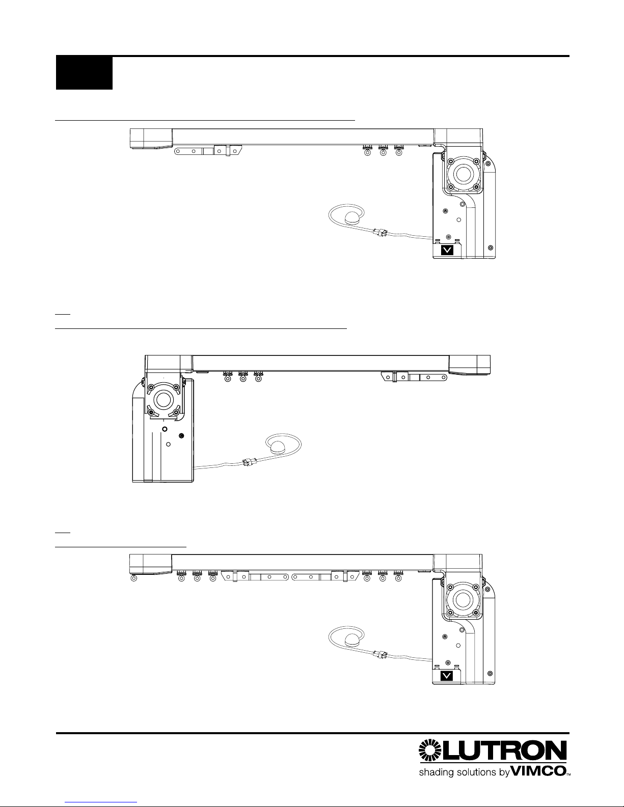
ONE WAY DRAW SYSTEM – RIGHT DRAW SHOWN
OR
ONE WA
Y DRAW SYSTEM – LEFT DRAW SHOWN
2
OR
SPLIT DRA
W SYSTEM
Carton Contents
1
Sivoia® Drapery
Page 3
• #2 Phillips Screwdriver
• 1/8 in. Straight Blade Screwdriver
• Power Drill: Drill Bits, Screwdriver Attachments
• Level
• Pliers
• Tape Measure
• Wire Cutter
• Wire Stripper
3
Carton Contents
1
Tools Required
2
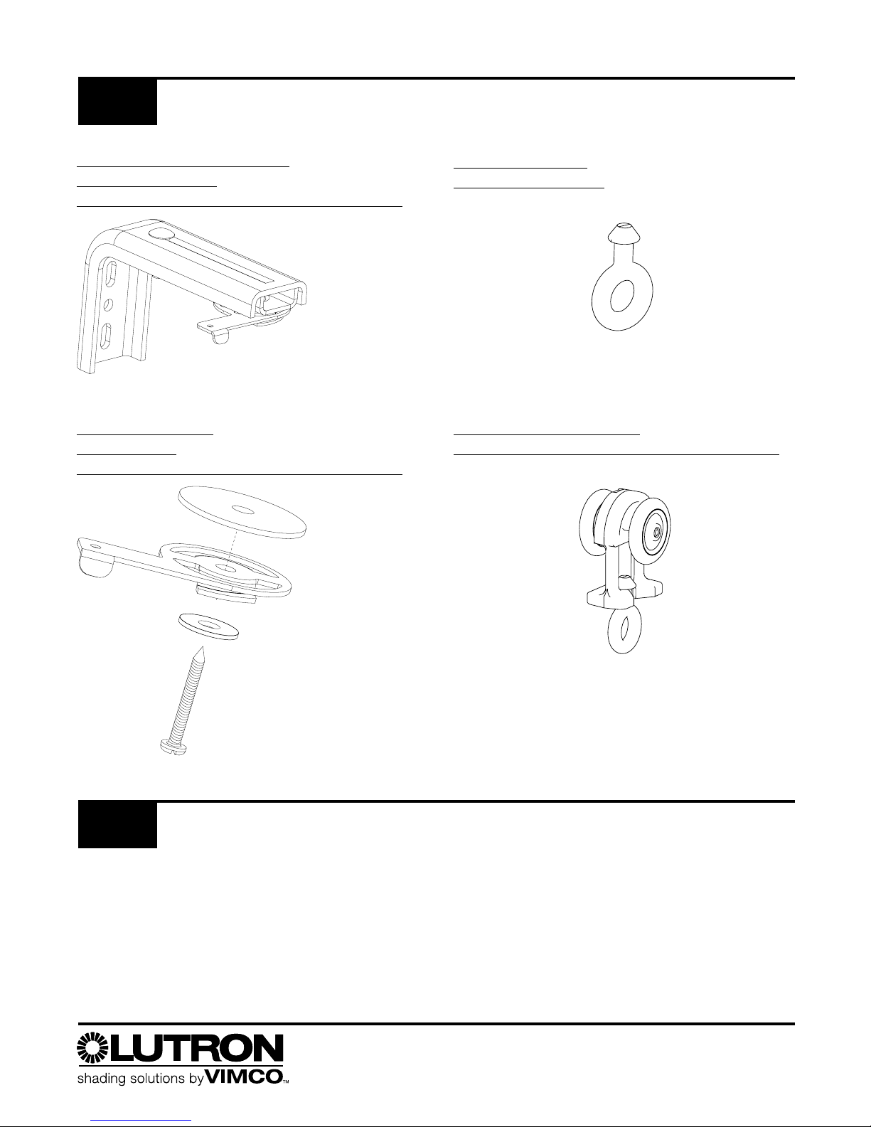
W ALL MOUNT BRACKETS
WITH CAM LOCK
( quantity depends on system width)
ONE HOOK EYE
(split draw only)
AUXILIARY CARRIERS
(
quantity depends on system width)
CEILING MOUNT
C AM LOCKS
(
quantity depends on system width)
Sivoia® Drapery
Page 4

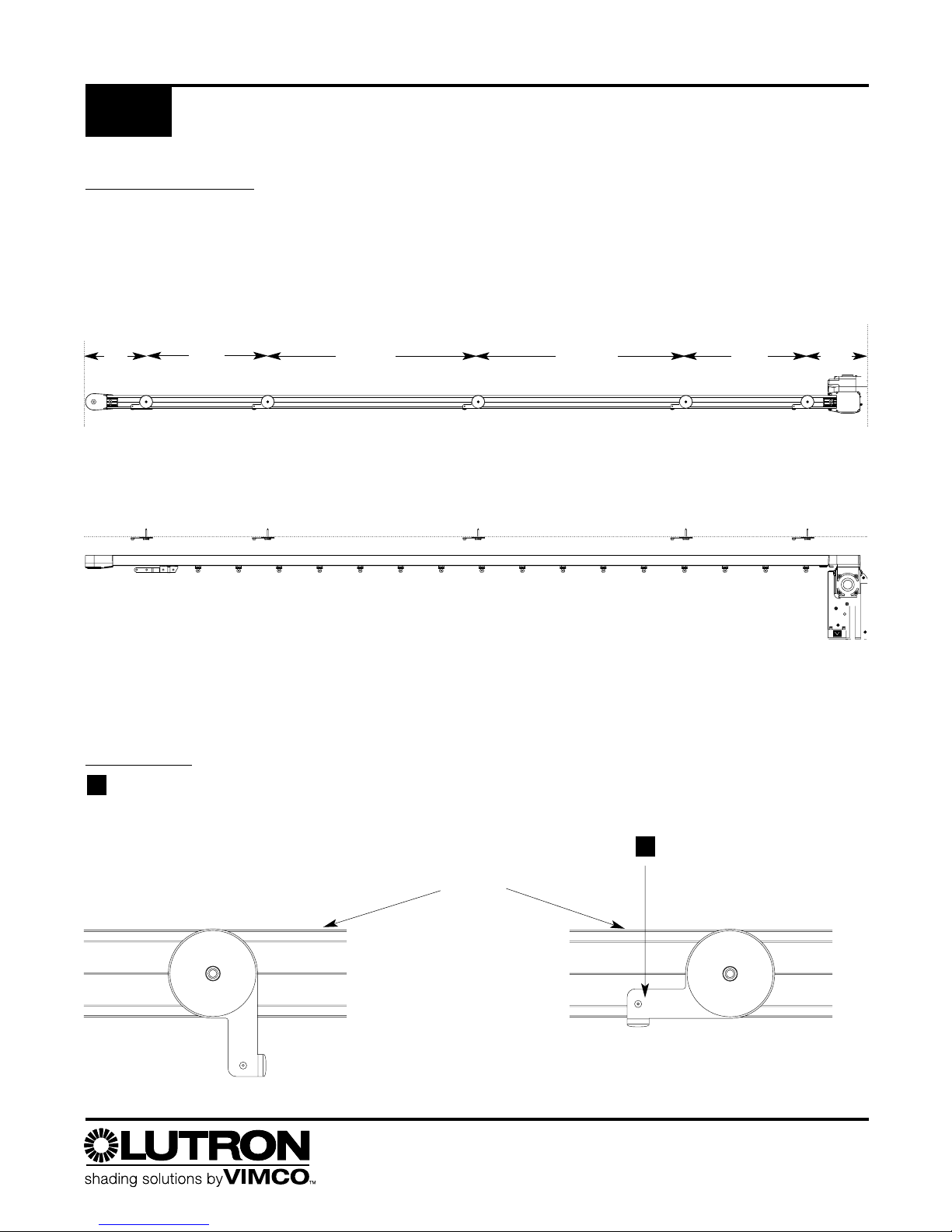
Mount the drapery track to the wall using the wall mount “L” brackets. Mount the brackets using the spacing illustrated
below. Mount each end bracket at a maximum dimension of between five (5) and six (6) inches from each end of the
track. Space the next bracket on both sides 16 in from the end brackets. Space the remaining brackets 16-24 in apart.
Note: All screws must be securely fastened to stud or structural member.
Top View
BRACKETS MUST BE MOUNTED STRAIGHT AND LEVEL
Each bracket must be mounted along a straight and level line. The drapery track must be straight and level to
operate properly. When the wall brackets are securely mounted, install the track to the brackets using the cam locks.
(SEE ILLUSTRATIONS BELOW FOR CAM LOCK OPERATION)
Side Elevation View
C
AM LEVER
4
Wall Mounting the Drapery Track
3
Window/Wall Side
Level
Line
track
Top View
bracket
3.5-6 in
Adjustability
Push in cam lever
until the tab is
against the track
2
Cam is fully
engaged
when the tab
on the cam
is against
the track.
Orient the cam lever in this
position to engage the track
with the cam lock.
1
16 in 16-24 in
5-6
in
16-24 in 16 in
5-6
in
Sivoia® Drapery
Page 5
TRACK MOUNTING
Mount the drapery track to the ceiling using ceiling mount cam locks. Mount the cam locks using the spacing guidelines shown below. Mount each end cam lock at a maximum dimension of between five (5) and six (6) inches and
minimum dimension of five (5) inches from each end of system. Space the next bracket on both sides 16 in from the
end brackets. Space the remaining brackets 16-24 in apart.
Note: All screws must be securely fastened to stud or
structural member.
Top View
The brackets should be mounted on a straight and level line. If the contour of the ceiling is not straight and level,
use shims between the cam lock bracket and the ceiling to compensate for the irregularities.
To mount the track to the brackets, position all the cam lock lever arms to the unlocked position
(see “unlocked” diagram below). Position the track up against the cam lock brackets and rotate
the cam lock arm to the locked position.
C
AM LEVER
Orient each cam lever in the position shown below.
This unlocked position allows the track to engage
the cam.
1
5
Ceiling Mounting the Drapery Track
3
Top View
16 in 16-24 in
5-6
in
Level
Line
Window/Wall Side
Swing cam lock arm to lock
track to cam lock bracket. Cam
is fully engaged when the tab
on the cam is against the track.
2
Track
Unlocked
Locked
16-24 in 16 in
5-6 in
Sivoia® Drapery
Page 6

LOADING THE CARRIERS
The drapery carriers are installed at the factory, however, the required number of carriers must be verified. Draperies require
one carrier per hook. The first two drapery hooks should hook on the master carrier for left, right and split draw systems (see
respective diagrams on the next two pages). The number of carriers required is equal to the number of drapery hooks in
fabric minus four (4).
LEFT AND RIGHT SINGLE DRAW SY
STEMS
Idle End
TO ADD OR REMOVE CARRIERS:
Single Draw: Left or Right
Pry out square plug on the motor side of the track.
Insert or remove auxiliary carriers through the
square hole in the track until the proper number of
carriers are installed.
Replace plastic square plug by pushing it up into
the square home until it snaps into place.
3
2
1
Motor
Housing
hooks for
last two (2)
drapery
hooks
Master Carrier
6
Carrier Installation – Left and Right Draw Systems
4
First two (2)
drapery hooks
should hook here
3
Pry out here using
flat blade screw driver
1
Auxiliary Carriers Motor End
The number of carriers required is
four less than the total number of
hooks on the drapery. The first two
drapery hooks should hook to the
master carrier and the last two
drapery hooks should hook to the
motor housing.
Sivoia® Drapery
Page 7

SPLIT DRAW SYSTEMS
The motor side of the drapery track requires four less carriers than the total number of hooks on the drapery track.
The first two drapery hooks should hook to the master carrier and the last two drapery hooks should hook to the motor
housing. The number of carriers required is different for the idle side. The idle side of the drapery requires three less
carriers than the total number of hooks on the drapery. The first two drapery hooks should hook to the master carrier,
and the last drapery hooks should hook onto the hook eye on the idle endcap. See diagram below.
Idle end hook eye
Remove idle end cover
2
Carrier Installation – Split Draw Systems
4
7
TO ADD OR REMOVE C
ARRIERS:
Split Drive Systems
Follow the directions on page 6 for motor side plug
removal, and installation of the auxiliary carriers.
Remove screw that retains the idle end cover.
Remove idle and hook eye.
Insert or remove auxiliary carriers through the
square hole in the idler end cap until the proper
number of carriers are installed.
Install idle end hook eye and replace the idle end
cover using the screw removed in step 2.
4
3
2
1
Remove track plug on the
motor side. Follow the directions
given on page 6.
1
3
Idle end cover
retaining screw
4 2
Number of drapery
hooks minus three (3)
Number of drapery
hooks minus four (4)
Sivoia® Drapery
Page 8

DRAPERY HOOK SETTING
For the best system performance, a drapery hook setting of 1/2 in should be used. This allows the system to
operate with minimal noise.
DRAPER
Y FABRIC RETURN
Hanging Drapery Fabric
5
8
4.0-6.5 in (depends on wall
mount bracket extension)
.50
in
Sivoia® Drapery
Page 9

Description
2 conductors / #22-24 AWG
3 conductors (2 shielded, 1 common)
#24 AWG Belden
® wire model #1883A
3 conductors:
2 / #18-22 AWG (24 VAC power supply)
1 / #18-22 AWG (earth ground)
6 conductors:
2 / #16 AWG (24 VAC power supply)
1 / #18 AWG (earth ground)
3 #22 AWG shielded + 1 #24 AWG
common (comm link)
(
Lutron wire part no. SV-CBL-MDU-250)
3 conductors #22 AWG
Lutron model # SV-IR-EXT-10
Maximum Length
Control to MDU: 250 ft.(76 m)
4000 ft. (1333 m) per system
1000 ft. (333 m) from MDU to MDU
Transformer to MDU:
#18 AWG - 150 ft. (46 m)
#20 AWG - 100 ft. (31 m)
#22 AWG - 60 ft. (18 m)
MDU to
Sivoia power panel:
200 ft. (61 m)
50 ft. (15 m) per system total of 5 SV-IR-EXT-10, 10 ft.
(3 m) each
Do not connect if there is only one MDU in the system. If there are
multiple MDU's in the system,the MDU's must be wired together. Connect the
MUX, Common, and MUX terminals of each MDU together in a daisy chain or
homerun configuration.
To a Sivoia wall mounted keypad, or a Sivoia interface such as the SV-CCI-GRP
or the SV-GRXI. The CNTRL1 and CNTRL2 wires are
polarity sensitive.
Wire to a Sivoia 100VA plug-in transformer, junction box mount transformer,
or a
Sivoia power panel. Each MDU must be EARTH grounded. One Sivoia
transformer can power ONLY ONE MDU regardless of drapery size.
Control
Comm
Link
Power
Supply
IR Connector
System Wiring – Single MDU
6
9
CONNECTING WIRES TO THE MDU TERMINAL BLOCK
The terminal block located at the bottom of the MDU is the wire
connection point for: power, communication, keypads, and interfaces.
1. Remove terminal block cover by pressing in on the cover and then
pulling downward.
2. Grasp terminal block and pull down to separate from connecting block.
3. Connect wires to the terminal block according to the diagram below.
4. Replace the terminal block and the terminal block cover.
Wire Type
Control
A
Comm Link
B
Power Wires
C
Comm & Power
D
B &
C combined
in one cable
SV-IR
E
Extension Cable
A
E
B
C
Sivoia® Drapery
B
1234567
Cntrl 1
Cntrl
2
MUX
Common
MUX
AC
Ground
8
AC
Page 10

Common
MUX
MUX
1234567
8
Cntrl
1
Cntrl
2
Ground
AC
AC
Common
M
UX
M
UX
1234567
8
Cntrl
1
Cntrl
2
Ground
AC
AC
Common
M
UX
M
UX
AC
G
N
D
AC
Wire to a Sivoia plug-in transformer, junction box mount transformer, or
a Sivoia power panel. Each MDU must be EARTH grounded. One Sivoia
transformer can power ONLY ONE MDU regardless of system width.
To a Sivoia wall
mounted keypad,
or a
Sivoia interface
A maximum of 64 MDUs can
be wired together per system
MDU Terminal Blocks
Control
Comm Link
Comm Link
Power Supply
Control
Next
MDU
Next
MDU
Comm Link
Power Supply
6
System Wiring – Multiple MDUs
10
Description
2 conductors / #22-24 AWG
3 conductors (2 shielded, 1 common) /
#24 AWG Belden
® wire model #1883A
3 conductors:
2 / #18-22 AWG (24 VAC power supply)
1 / #18-22 AWG (earth ground)
6 conductors:
2 / #16 AWG (24 VAC power supply)
1 / #18 AWG (earth ground)
3 #22 AWG shielded + 1 #24 AWG
common (comm link)
(
Lutron wire part no. SV-CBL-MDU-250)
3 conductors #22 AWG
Lutron model # SV-IR-EXT-10
Maximum Length
Control to MDU: 250 ft.(76 m)
4000 ft. (1333 m) per system
1000 ft. (333 m) from MDU to MDU
Transformer to MDU:
#18 AWG - 150 ft. (46 m)
#20 AWG - 100 ft. (31 m)
#22 AWG - 60 ft. (18 m)
MDU to
Sivoia power panel:
200 ft. (61 m)
50 ft. (15 m) per system total of 5 SV-IR-EXT-10, 10 ft.
(3 m) each
Wire Type
Control
A
Comm Link
B
Power Wires
C
Comm & Power
D
B &
C combined
in one cable
SV-IR
E
Extension Cable
B
B
A
C
B
A
E E
C
Sivoia® Drapery
Page 11

Open Limit: The position the shade moves to
when it opens.
Close Limit: The position the shade moves to
when it closes.
Mode Button
Open and
Close Buttons
Set Button
Display on bottom of MDU
SINGLE MDU
The motor drive unit should come from the factory with open and close limits set. In order to change the factory limits,
follow the steps below. If there is only one MDU in the system, open limit and close limit are the only setups required.
Follow the programming steps outlined in the programming table below. If the system has multiple MDU's, follow the
single MDU setup directions for each MDU and then continue with the setup codes for multiple MDU systems on the
next page.
11
7
Configuring the Motor Drive Unit (MDU)
Steps
Step 1
Step 2
Set
Press the Set button to save the
current position as the “Open Limit.”
The display will read and blink
for 4 seconds, then go blank.
Press the
Set Button to save the
current position as the “Close Limit.”
The display will read and blink
for 4 seconds, then go blank.
Mode
Open Limit: Press the
Mode button on the
MDU until the display
reads
Close Limit: Press the
Mode button on the
MDU until the display
reads
Adjust
Use the Open and Close buttons on the MDU
to adjust the drapery to the Open position
desired. When open the auxiliary carriers
should not be tightly stacked together.
Use the
Open and Close buttons on the MDU
to adjust the drapery to the Closed position
desired.
Sivoia® Drapery
MODE
OPEN
CLOSE
SET
Page 12

All MDU’s with the same room
address and the
same address
MUL
TIPLE MDU SET-UP CODES
Program each MDU per instructions on page 11.
Link Address:
Each MDU must be set to a unique Link Address number to allow the MDU's to communicate on the communication
link. There are 64 link addresses available, meaning the maximum number of MDU's in a single system is 64.
Room Address: The room address groups MDU's on the communication link. A group is defined as all MDU's with the same room
address number. There are 32 room addresses available in a single system, therefore, a system can have up to 32 groups.
Typically, all MDU's in a room will be set to the same room address. Use the room address to help determine how keypads will
control the MDU's in the system. Refer to the control station setting table below for information on how the room address setting
affects how the system is controlled by keypads or interfaces.
IR Address: Used to set the IR address a MDU will respond to. Some IR hand controls have the ability to control subgroups of
draperies within a group, as defined by the room address described above. There are 8 subgroups available. Each IR address (subgroup) is made up of two parts, the IR address number (1,2,3 or 4) and its drapery location (F or r), the FRONT drapery or the REAR
drapery. Any number of MDU's can have the same IR address. The IR address can also be used to determine subgroups
of the MDU's when a keypad or interface is used to control the system. Refer to the control station setting table below for information on how the IR address affects how the system is controlled by keypads or interfaces.
Control Station: Determines which MDU's in the system will respond to a "Group" keypad or "Group" interface control that is
wired to the MDU being setup. It is not necessary to change the control station setting of an MDU that does not have any keypads
or interfaces wired to it.
There are two types of Sivoia keypads and
interfaces,
group and individual types. The
table to the left describes how a group type
controls a system depending on the
setting of the MDU it is wired to. An individual
type only controls the MDU it is wired to,
regardless of the setting of the MDU it
is wired to.
Group keypads/interfaces and individual
keypads/interfaces can be wired to the same
MDU. A maximum of 9 keypads/interfaces
can be wired to one MDU.
Any keypad or interface
CANNOT be wired to
more than one MDU.
SPECIAL NOTES:
Control Station Setting Table
MDU
CS
Setting
0
1
2
Which MDU’s in a System Will
Respond
All MDU’s with the same room
address
All MDU’s in the system
All MDU’s with the same room
address
and the same Front (F)
or Rear (r) assignment in the
address
4
3
5
All MDU’s with the same room
address
and the same number (1,
2, 3, or 4) in the address setting
All Front MDU’s or all Rear MDU’s
in the system
What MDU Address Settings
Determine which MDU in the
System Will Respond
Room address
Room address
IR address
Not dependent on and
Room address
Front or Rear in the
IR address
Room address
Same number (1, 2, 3, or 4) in the
IR address
Front or Rear in the
IR address
12
7
Configuring the MDU
Preset Lockout: Turns off the ability to set or adjust PRESET stop points. To activate, set the scene lockout
setting to 1. To deactivate, set the scene lockout setting to 0. Changing this setting on any MDU will adjust all the
MDU's in the system. It is not necessary to deactivate the scene lockout setting from the same MDU it was activated it on.
Sivoia® Drapery
Page 13

MOUNTING THE IR EYE
13
8
Infrared Control
Connect the SV-IR
receiver to the wire
connector on the MDU
Mount the IR eye to the wall, the ceiling or even a non-moving edge of the drapery fabric using a clip. Make sure
the location of the eye is not obstructed by an object.
The SV-IR allows the MDU to be controlled directly with a
Sivoia Infrared Handheld Transmitter (SV-OCIT, SV-3PIT,
or SV-4GD-OCIT). The SV-IR receiver connects to the MDU via a 20 in (51cm) cable. This provides the SV-IR
receiver ample mounting range to offset any infrared signal restriction caused by a protective/decorative covering
for the shade system. To extend the IR receiver mounting range, add up to five (5) SV-IR-EXT-10 extension cables
(10 ft [3 m] each).
Note: To control an individual drapery with an IR transmitter, the SV-IR must be connected to that MDU. If there
is a Group/Subgroup of MDU’s with the same Room/IR Address (see page 11), the SV-IR need only be connected to one of those MDU’s to control the entire Group/Subgroup.
• The SV-IR receiver must be located to allow line-of-sight reception of infrared signals.
• The IR transmitter has a range of 30 ft for the SV-IR to receive its signal.
• The SV-IR must
NOT be located near lighting fixtures or in direct sunlight.
• The SV-IR must be located within 50 ft (15 m) of the MDU it is connected to. Add up to five SV-IR-EXT-10
extension cables (10 ft [3 m] each).
Sivoia® Drapery
Page 14

PROBLEM SOLUTION
The draperies will not open or close. 1. Check power to the motor unit by pressing the MODE
button. If the LED display does not show
oL check that:
• transformer has power
• MDU is wired correctly
• power wiring terminal is not miswired or
disconnected
2. Try to open and close the drapery using the buttons
marked open and close on the motor drive unit. If the
drapery does not respond, check for and clear all
obstructions.
3. Check that the Open and Close limits are set correctly.
The Drapery does not respond to keypads or IR. 1. Check that power is connected to the drapery.
2. Check that MDU terminal block is connected securely
and wired correctly.
3. If using wall keypad, check that wall keypad has been
wired correctly.
4. If using IR remote, confirm that SV-IR, infrared receiver
is wired to MDU correctly, and is not obstructed.
5. If using IR remote, check transmitter batteries.
Draperies do not move together in a group 1. Confirm that all MDUs are wired correctly, including
power and Comm Link.
2. Confirm that each MDU has a unique link address, and
a common room address.
3. Confirm that keypad is a group keypad.
Drapery will not move to full open or full close 1. Confirm that open and close limits are set correctly.
2. Confirm that drapery fabric is not obstructed or caught
on something.
3. Confirm that drapery fabric is hanging from only the 1st
and 4th holes of the master car.
14
9
Troubleshooting
Sivoia® Drapery
Page 15

SIVOIA MOTORIZED DRAPERY SYSTEM
EIGHT YEAR LIMITED WARRANTY
Vimco warrants, for eight years from shipment, each
new
Sivoia Motorized Drapery System to be free from
defects in materials or workmanship under conditions of
normal use and specified ambient temperature when
installed and operated in accordance with Vimco product
specifications, applicable local electrical and building
codes, applicable National Electrical Code
® provisions,
and the Safety Standards of Underwriter's Laboratories.
WHAT VIMCO WILL DO
Upon the return of a system or system component,
subsequently determined by Vimco to be defective,
Vimco will, in its sole discretion, repair or replace the
defective system or system component, provided that
Vimco was promptly notified of the alleged defect within
the warranty period, and provided that the system or
system component was properly installed, wired,
insulated, used, and maintained, as determined solely by
Vimco. Vimco shall not be required to remove, install, or
re-install any system or system component alleged to be
defective.
Vimco will issue a credit for the cost of the repair or the
replacement in accordance with the following schedule:
For the first 2 years after the date of shipment 100%
For years 3, 4, and 5 after the date of shipment 50%
For years 6, 7, and 8 after the date of shipment 25%
WHAT THIS WARRANTY
DOES NOT COVER
1. Damage or improper operation determined by Vimco
to be due to normal wear and tear, or to abuse,
misuse, or accident, such as:
a. Use of incorrect line voltages;
b. Use of incorrect fuses or circuit breakers;
c. Failure to follow operating instructions provided by
VIMCO;
d. Unauthorized repairs or adjustments or alterations;
e. Direct exposure to corrosive materials;
f. Vandalism;
g. Fire, flood, "Acts of God", and other factors beyond
the control of VIMCO.
2. The cost of labor, including any labor required to
remove, install, or re-program any replacement item.
3. Components and equipment external to the
Sivoia
Motorized Drapery System, such as:
a. Non-Lutron lighting and automation systems;
b. Building wiring; and
c. Other manufacturers’ equipment, including, but not
limited to:
i. Time clocks;
ii. Audio-visual equipment; and
iii. Photo sensors.
4. The cost of repairing or replacing property or
equipment other than the warranted system.
HOW TO GET SERVICE
UNDER THIS W
ARRANTY
Should you experience the need for service under this
warranty, please contact your
Sivoia Motorized Drapery
System service representative immediately; or
Contact VIMCO by telephone toll-free at:
1-800-446-1503; or
By mail to: VIMCO Shading Systems
11520 Sun Shade Lane
Ashland, VA 23005
or;
By E-mail: info@vimco.com
15
10
Limited Warranty
Sivoia® Drapery
Page 16

LIMITATIONS AND EXCLUSIONS
THIS WARRANTY IS EXCLUSIVE. THERE ARE NO OTHER
EXPRESS WARRANTIES.
THE IMPLIED WARRANTY OF MERCHANTABILITY IS
LIMITED TO TWO YEARS FROM THE DATE OF SHIPMENT.
VIMCO SHALL NOT BE LIABLE FOR ANY REPAIR WORK
UNDERTAKEN WITHOUT ITS PROPER WRITTEN CONSENT,
OR FOR INCIDENTAL, CONSEQUENTIAL, OR SPECIAL
DAMAGES. VIMCO’S LIABILITY ON ANY CLAIM FOR
DAMAGES ARISING OUT OF OR IN CONNECTION WITH
THE MANUFACTURE, SALE, INSTALLATION, DELIVERY,
USE, REPAIR, OR REPLACEMENT OF THE SHADING
SYSTEM SHALL NEVER EXCEED THE PRICE PAID FOR
THE SYSTEM. SOME STATES DO NOT ALLOW
LIMITATIONS ON HOW LONG AN IMPLIED WARRANTY
LASTS, SO THE ABOVE LIMITATION MAY NOT APPLY TO
YOU. SOME STATES DO NOT ALLOW THE EXCLUSION OR
LIMITATION OF INCIDENTAL OR CONSEQUENTIAL
DAMAGES, SO THE ABOVE LIMITATION OR EXCLUSION
MAY NOT APPLY TO YOU.
This product may be covered under one or more of the
following U.S. Patents: 5,671,387; 6,313,588;
6,346,781; DES. 370,663; DES. 378,814; DES. 437,585;
DES. 450,043; and DES 462,332. and corresponding
foreign patents. U.S. and foreign patents pending.
Lutron, the sunburst logo, and Sivoia are registered
trademarks and “Shading Solutions by Vimco” is a
registered trademark of Lutron Electronics Co., Inc. The
VIMCO logo is a registered trademark of Virginia Iron &
Metal Company, Inc. NEC is a registered trademark of
the National Fire Protection Association, Quincy,
Massachusetts.
© 2004 Virginia Iron & Metal Company, Inc.
Internet: www.vimco.com, www.lutron.com
16
10
Limited Warranty
Lutron Electronics Co., Inc.
7200 Suter Road • Coopersburg, PA 18036 U.S.A.
Made and printed in U.S.A. 9/04 P/N 045-014 Rev. B
Sivoia® Drapery
 Loading...