

Page 1

Setup guide
A detailed guide for programming and operating a Lutron®
RadioRA-SR wireless single room lighting control system
English
Español
Français
Page 2

English
Español
Français
If you have any questions, the Lutron® Technical Support Hotline is ready to help 24 hours a day,
7 days a week. Call us at 800.523.9466 for immediate assistance.
For Installation Guides, Setup Tools, or more information concerning your RadioRA
please visit http://www.lutron.com/radiorasr.
Lutron 24/7 Technical Support—800.523.9466
®-SR system,
24/7 Technical Support—800.523.9466
Page 3

Table of contents
Overview
About RadioRA-SR .........................................................................................................................2
Planning and design
System planning ............................................................................................................................3
Programming keypads
Assigning devices to a keypad ........................................................................................................5
Default zone control levels and window treatment positions ............................................................8
Adjusting default levels / positions from a keypad .............................................................................9
Programming occupancy / vacancy sensors
Assigning sensors .........................................................................................................................11
Integration
Assigning devices to the Integrated Scene Controller ....................................................................12
Adjusting default levels / positions from an Integrated Scene Controller ..........................................13
Protocol
Basics ........................................................................................................................................16
Communication setup .................................................................................................................19
Verify assignments and set up Integration IDs .............................................................................20
Control / Command .....................................................................................................................22
Monitor .......................................................................................................................................25
Error reporting ............................................................................................................................26
Advanced programming .............................................................................................................27
Table of integration operations ....................................................................................................29
English
Español
Français
Resetting devices to factory settings
About resetting devices to factory settings ....................................................................................30
Resetting zone controls to factory settings ....................................................................................30
Resetting keypads to factory settings ............................................................................................30
Resetting Pico wireless controls to factory settings .......................................................................30
Resetting sensors to factory settings .............................................................................................31
Resetting Integrated Scene Controller to factory settings .............................................................31
Resetting window treatments to factory settings ...........................................................................31
Programming worksheets
Programming worksheets .............................................................................................................32
Troubleshooting
Troubleshooting guide ...................................................................................................................33
Contact Lutron
Contact information .........................................................................................................Back Cover
Lutron | 1www.lutron.com/radiorasr
Page 4

English
Off
AD
JUST
O
N
Español
Overview
About RadioRA®-SR
RadioRA-SR is a system of lighting controls, window treatments, keypads, and sensors that
communicate wirelessly to provide total control of electric and natural light in a single room.
RadioRA-SR adds the magic of light control to any home entertainment area. Lutron provides
uncompromising reliability through innovative wireless communication technology. Lutron ensures
that your system will work every time by combining RF technology, patented by Lutron, with
unrivaled quality.
System components
Zone controls
Dimmers
Replace existing switches to control individual lights in your room.
Remote dimmers available for 3-way dimming.
Switches
Replace existing switches to control individual lights in your room.
Remote switches available for 3-way switching.
SRD-6D-*
SRD-10D-*
SRD-10ND-*
SD-RD-*
SRD-8ANS-*
SD-RS-*
Français
Keypads
System enhancements
Window treatments
Table lamp dimmers
Plug in lamp dimmers to control table lamps.
Wall-mount keypads
Backlit and engravable wall-mount keypads control zone controls, window
treatments, and scenes at the touch of a button.
PicoTM wireless control
Battery-powered, retrofit, portable keypads for zone controls and window
treatments.
Integrated Scene Controller
Communicates with devices such as universal remote controls and touch
screens. This allows you to adjust the levels of zone controls and window
treatment positions at the same time as your audio and video gear.
Occupancy and vacancy sensors
Provides energy savings by turning lights off when room is unoccupied and
turns lights on automatically when you enter the room.
Sivoia® QS Wireless roller shades
Improve your viewing experience by quietly covering windows to eliminate glare and reflections.
SRD-3LD-**
SRD-W3B-*
SRD-W5BRL-*
SRD-W7B-*
SRD-P3BRL-L*
SRD-P3BRL-S*
SR-NWK-E
LRF2-OCRB-P-WH
LRF2-VCRB-P-WH
Sivoia QS Wireless drapery track
Showcase your projection screen, adjust the aspect ratio of the viewing area, and enhance the room’s
décor with curtains controlled by a Lutron® drapery track.
Note: The minimum system requirement is one (1) zone control or window treatment, and one (1) keypad or Integrated Scene Controller.
* For available colors and finishes please visit www.lutron.com/radiorasr.
** Available in Snow (SW) and Midnight (MN).
2 | Lutron
24/7 Technical Support—800.523.9466
24/7 Technical Support—800.523.9466
Page 5

Planning and design
System planning
A properly planned RadioRA®-SR system is easy to use and provides the maximum benefits.
Planning a system involves making a number of important decisions. Here are some of them:
Where will I install the dimmers and switches?•
Where will I install the keypads?•
Where will I install the Integrated Scene Controller?•
What universal remotes will control this system?•
How will I program the system to control the lights and window treatments?•
How will I label the keypad buttons?•
Select locations of keypads, dimmers, and window treatments
All system components
must be within this area.
Integrated Scene Controller
near Audio Visual (AV)
equipment for easy integration
English
Español
Français
Drapery tracks for
windows
Tabletop dimmer for
reading lamp
30 ft (9 m)
Keypads at entrance
for lights and window
treatments
Dimmers for sconces
and downlights
System capacities
Maximum devices per system 10 (including the Integrated Scene Controller)
Maximum Integrated Scene
Controllers per system
RF Range Devices must be within 30 ft (9 m) of each other (except remote
1
dimmers SD-RD and switches SD-RS)
Installation
After planning and designing the layout of the system, install the system devices according to the
installation instructions that were packaged with each device.
Lutron | 3www.lutron.com/radiorasr
Page 6

Planning and design
System planning (continued)
Define scenes and engraving
Use the Programming worksheets section on page 32 of this guide to help define your
programming. Below is a sample worksheet.
English
Español
Français
Keypad Type:
Location:
Serial Number:
(Located on the Keypad)
Scene Engraving
1
2
3
4
5
6
5 button with raise/lower wall mount
Entrance doorway
0000040224456
Relax
Gaming
Sports
Movie
All Off
Zones
1 2 3 4 5 6
Downlights
50% 25% 10%
60% 50% 70%
30% 10% 65%
off 1% 1% closed
off off off closed
Accents
Lamp
Unaffected
Unaffected
Unaffected
Drapery
7
Raise/Lower Always raises/lowers lights while being
pressed
Identify universal remote control
If you choose to integrate your system with your audio-visual (AV) equipment, you will need to:
select a universal remote control to integrate with RadioRA•
add the Integrated Scene Controller to your system•
The Integrated Scene Controller provides RS232 or Ethernet control of the RadioRA-SR system. A
detailed explanation is provided in the Protocol section on page 16 of this guide. The manufacturers
listed below offer products that are compatible with the RadioRA-SR system.
AMX•
HomeLogic•
NetStreams• ®
RTI•
Universal Electronics•
Philips remote shown Names listed above are trademarks of their respective companies.
®
®-SR
®
ELAN• ®
Life|ware• TM
Philips• ®
Savant•
Universal Remote Control •
4 | Lutron
24/7 Technical Support—800.523.9466
24/7 Technical Support—800.523.9466
Page 7

LUTRON
Programming keypads
About assigning devices to a keypad
After all RadioRA®-SR devices have been installed, the keypads must be programmed to control a
set of zone controls and/or window treatments. When a button is pressed on a keypad, the assigned
controls and window treatments go to specific levels or positions. The combined levels of zone
controls and positions of window treatments for a particular scenario are called scenes.
Example:
When watching a movie you would like to dim the lights so that the screen can be viewed easily.
Once all the keypads are programmed, the preferred light levels for watching a movie can be recalled
by pressing one scene button on a keypad column.
Each RadioRA-SR system contains 16 programmable scenes and one Off scene. The Off scene,
when activated, will send all assigned zone controls to the Off state and close all window treatments.
Unlike the 16 programmable scenes, the Off scene may not be edited. A keypad can only access
a limited number of scenes based on how many scene buttons are part of the keypad column. The
Integrated Scene Controler can access all 16 scenes through the RS232 or Ethernet ports.
Keypad Examples:
- 3 button columns can only access scenes 1,3 and Off
- 5 button columns can only access scenes 1,2,3,4 and Off
- 7 button columns can only access scenes 1,2,3,4,5,6 and Off
English
Español
Français
Note: Scenes 7-16 can be accessed through the Integrated Scene Controller by using Integration
commands. See the Protocol section starting on page 16.
Programming a keypad column consists of:
1) Assigning zone controls, keypads and window treatments to a keypad column according to
the Assigning devices to a keypad section below.
2) Saving the desired zone control levels and window treatment positions for each scene button
according to the Adjusting default levels/positions from a keypad section on page 9.
Note: Once the keypads are programmed, assign all zone controls, keypads, and window treatments
to the Integrated Scene Controller according to the Assigning devices to the Integrated Scene
Controller section on page 12.
Assigning devices to a keypad
1. Enter assign mode – press and hold the top and bottom button
of the desired column until the Light Emitting Diode(s) (LED)
begin(s) to flash (approximately 6 seconds). If a keypad column
was previously programmed, all of the LEDs in the column will
scroll sequentially. If this is the first time a keypad column is
programmed, only the top and bottom LEDs will flash alternately.
The LED on the Pico
is in assign mode.
Note: The keypad will automatically exit assign mode after 10
minutes.
Note: If assigning devices to a Pico wireless control, skip step 2
and proceed directly to step 3.
TM wireless control will continue to flash while it
Lutron | 5www.lutron.com/radiorasr
Page 8

Programming keypads
Assigning devices to a keypad (continued)
2. Press each keypad button between the top and bottom buttons
to add the buttons to the column. Once pressed, the LED next to a
button will flash in sequence with the other LEDs, indicating that it
is now part of the keypad column.
English
3. Assign zone controls and window treatments to the keypad
column
a. Assign dimmers / switches – press and hold the tapswitch
Español
b. Assign window treatments – press any button on the drive
Note: For consistent operation, it is recommended that all zone
controls and window treatments in a single room be assigned to
every keypad in that room.
Français
Note: If assigning devices to a Pico
and proceed directly to step 5.
4. Assign other keypad columns – press and hold the bottom
button of the keypad column to be assigned until all the LEDs on
it begin to flash (approximately 6 seconds). While the first keypad
is in assign mode, its LEDs will scroll and the LEDs on assigned
keypads will continue to flash simultaneously.Assigning a keypad
column to another keypad column is useful for making the LEDs
on all keypad columns track each other. All keypads in a room
should have the same set of zone controls and window treatments
assigned to them.
on the device until the load flashes 3 times (approximately
6 seconds). The LEDs on assigned dimmers / switches will
continue to flash while the keypad is in assign mode.
and the green LED will flash.
TM wireless control, skip step 4
5. Assign the Integrated Scene Controller - press the Assign
button of Column 1 or 2 of the Integrated Scene Controller. The
corresponding Assign LED will flash red when Column 1 or 2 on
the Integrated Scene Controller has been assigned to a keypad.
To assign Column 3 or 4 of the Integrate Scene Controller to a
keypad, please refer to the Assign Column 3 or 4 to a keypad
that is in assign mode section on page 27. Assigning the
Integrated Scene Controller to a keypad allows the LEDs on the
keypad to track when a scene is selected on Column 1, 2, 3 or
4 of the Integrated Scene Controller. When an Integrated Scene
Controller column is assigned to a keypad, the Assign LED on the
Integrated Scene Controller will flash green several times to signify
that there is a button press occurring on that keypad.
Note: To unassign a device that is assigned, use the same method
to assign it as described in the Assigning devices to a keypad
section starting on page 5.
6 | Lutron
24/7 Technical Support—800.523.9466
24/7 Technical Support—800.523.9466
Page 9

LUTRON
LUTRON
Programming keypads
Assigning devices to a keypad (continued)
6. When all devices have been assigned, exit assign mode by
holding the top and bottom buttons of the selected column until
the LED(s) stop(s) scrolling or flashing (approximately 3 seconds).
7. Program all keypads – repeat steps 1-4 of Assigning devices to
a keypad, starting on page 5, for every keypad in the RadioRA
SR system. When a second keypad column is assigned to the
first keypad column, pressing a scene button on the first keypad
column will activate the corresponding LEDs on both the first and
second keypad columns. Pressing a scene button on the second
keypad column will only activate the corresponding LED on the
second keypad column. The first keypad column must also be
assigned to the second keypad column in order to allow the LEDs
on both keypad columns to be activated when a scene button is
pressed on either keypad column.
®-
English
Español
Français
8. Confirm assignment by individually pressing every button on a
keypad. Assigned devices respond to the button press by going to
the default level for that scene. During keypad operation, the LED
next to the button is illuminated when the corresponding button is
pressed. The LED turns off after another button is pressed on that
keypad column, on another assigned keypad column, or if a level
of a zone control assigned to the keypad column changes.
After a button is pressed on a Pico
to the top button will flash for 1-2 seconds and turn off to conserve
battery power.
TM wireless control, the LED next
Lutron | 7www.lutron.com/radiorasr
Page 10

LUTRON
100%
50%
Off
Programming keypads
Default zone control levels and window treatment positions
After lights and/or window treatments are assigned to keypad columns, the assigned devices will
default to the levels listed below.
Default levels and positions for a 7 button wall-mount keypad
English
Español
Default levels and positions for a 5 button wall-mount keypad
Français
Scene Dimmers Switches Window Treatments
1 100% On Open
2 75% On 3/4 open
3 50% On 1/2 open
4 25% On 1/4 open
5 15% On Closed
6 1% On Closed
Off 0% Off Closed
Scene Dimmers Switches Window Treatments
1 100% On Open
2 75% On 3/4 open
3 50% On 1/2 open
4 25% On 1/4 open
Off 0% Off Closed
Raise / Lower
Buttons
Lights
raise / lower.
Raise will turn the
load on immediately
if off. Lower will not
turn the load off.
Window treatments
will NOT raise / lower
from a scene keypad.
Default levels and positions for a 3 button wall-mount keypad
Scene Dimmers Switches Window Treatments
1 100% On Open
3 50% On 1/2 open
Off 0% Off Closed
Default levels and positions for a PicoTM wireless control
Button Dimmers Switches Window Treatments
On / Open 100% On Open
Center 50% On 1/2 open
Off / Closed 0% Off Closed
Raise / Lower
Buttons
Lights
raise / lower.
Raise will turn the
load on immediately
if off. Lower will not
turn the load off.
Window treatments
raise / lower.
8 | Lutron
24/7 Technical Support—800.523.9466
24/7 Technical Support—800.523.9466
Page 11

LUTRON
Programming keypads
About adjusting default levels / positions from a keypad
You can customize the default levels or positions of the devices assigned to a keypad column by
using the steps below. All other keypad columns or Integrated Scene Controller columns that have
those devices assigned to them will access the same, newly customized levels or positions. The
column containing the button to be customized must have already been programmed according to
the Assigning devices to a keypad section on page 5.
English
Adjusting default levels / positions from a keypad
1. Press the button you wish to customize. The lights will dim and
the window treatments will move to the default level associated
with this button. Wait until the lights and window treatments stop
dimming and moving.
Note: The bottom scene button of a keypad column is the OFF
scene and will turn off all the devices assigned to that column. The
OFF scene cannot be modified or saved to a different scene.
2. Adjust each light and window treatment assigned to that column
as follows:
a. Set levels on dimmers – use the tapswitch to toggle the lights
on or off. Use the raise or lower button on the right side of the
dimmer to make adjustments to the desired light levels.
b. Set switches – use the tapswitch to toggle the lights on or off.
Español
Français
d. Set window treatment position – use the clockwise or
counter-clockwise buttons on the window treatment drive to
adjust the position.
3. Making zone controls and window treatments ‘unaffected’
(optional) – To make assigned devices not respond to a keypad
button press, you may make the devices ‘unaffected’. During
normal operation when you press a keypad button, a device that is
‘unaffected’ will ignore the button press. The light level or window
treatment position will not change. To make devices ‘unaffected’,
follow the corresponding step on the next page based on the type
of device to be made ‘unaffected’.
Lutron | 9www.lutron.com/radiorasr
Page 12

LUTRON
Programming keypads
Adjusting default levels / positions from a keypad (continued)
a. Make a dimmer ‘unaffected’ – if the dimmer is on, press the
English
b. Make a switch ‘unaffected’ – if the switch is on, turn it off
Español
d. Make a window treatment ‘unaffected’ – if the window
Français
tapswitch once to turn it off. After the dimmer is completely
off, hold the lower rocker until the three middle LEDs turn on
(approximately 6 seconds), signifying that the next level save will
be ignored. **
using the tapswitch. Pull the FASS
the tapswitch. While still holding the tapswitch, push the FASS
switch in. Continue holding the tapswitch until the LED flashes,
signifying that the next level save will be ignored. **
treatment is open, close it using either the clockwise or counterclockwise button. Release the button. After the window
treatment is closed, press and hold the same button used to
close the window treatment until the green LED blinks quickly
(approximately 10 seconds), signifying that the next position save
will be ignored. **
TM switch out. Press and hold
4. Press and hold the selected keypad button until the LED
flashes (approximately 6 seconds) to save the current levels. The
LED will blink rapidly for 1-2 seconds to confirm that the save was
successful. On keypad columns, the LED will turn back on. On
TM wireless controls, the LED will turn off.
Pico
** After a device becomes ‘unaffected’, you have 10 minutes to complete the level save for all zone
controls and window treatments.
Note: To change the ‘unaffected’ status of a zone control or window treatment, follow steps 1, 2,
and 4 in Adjusting default levels/positions from a keypad starting on page 9.
10 | Lutron
24/7 Technical Support—800.523.9466
24/7 Technical Support—800.523.9466
Page 13

Programming occupancy / vacancy sensors
About assigning sensors
Sensors may be assigned to single or multiple dimmers or switches. When the occupancy sensor
detects a person entering the room, the dimmer(s) fade on quickly and the switch(es) turn on. The
level that the dimmer(s) turn on to may be programmed to a customized level.
When the occupancy sensor detects that everyone has left the room, the dimmer(s) and / or
switch(es) will turn off.
Vacancy sensors can only turn off the dimmer(s) and / or switch(es) when the room is unoccupied.
The person must manually turn on the dimmer(s) and / or switch(es) when entering the room.
Assigning sensors
1. Enter assign mode on the sensor by pressing and holding the
Lights On and Lights Off buttons on the sensor simultaneously until
the orange LED inside the lens flashes (approximately 6 seconds),
then release the buttons. While in program mode, the LED will flash
once every 2 seconds, indicating the sensor is in assign mode.
2. Assign dimmers / switches by pressing and holding the
tapswitch on the dimmer / switch until the LED(s) on the device
flash and the load flashes three times (approximately 6 seconds).
English
Español
Français
Note: to unassign a previously assigned dimmer/switch, repeat
steps 1-3.
3. Exit assign mode on the sensor by pressing and holding the
Lights On and Lights Off buttons on the sensor simultaneously until
the LED inside the lens stops flashing (approximately 6 seconds).
4. Program the level that the dimmers will turn on to when the room
is entered.
a. Adjust the level(s) of the dimmer(s) – adjust the level(s) of the
dimmer(s) using the raise or lower rocker on each dimmer.
Note: switches cannot be adjusted, they always turn on if assigned
to an occupancy sensor.
b. Save the level(s) of the dimmer(s) – press and hold the Lights
On button on the sensor for 6 seconds to save the level(s) that
the dimmer(s) will turn on to when someone enters the room.
c. Verify the level(s) of the dimmer(s) were saved correctly
– press and release the Lights Off button on the sensor to turn
the dimmer(s) and / or switch(es) off. Then press and release the
Lights On button and verify that the dimmer(s) turned on to the
desired level(s).
Note: Please refer to the installation instructions provided with the
sensor for additional features.
Lutron | 11www.lutron.com/radiorasr
Page 14
The Integrated Scene Controller provides a single integration point into a RadioRA®-SR system.
English
Español
Integration
About assigning devices to the Integrated Scene Controller
The Integrated Scene Controller is able to control up to 9 RadioRA-SR zone controls or window
treatments. The Integrated Scene Controller can be used to activate scenes in the system and set
or get zone control levels and window treatment positions. Each RadioRA-SR system contains 16
programmable scenes and one OFF scene. A keypad can only access a limited number of these
scenes based on how many scene buttons are part of the keypad column. The Integrated Scene
Controller can access all 16 scenes through the RS232 or Ethernet ports. This allows 3
remote controls or touch panels to control RadioRA-SR devices.
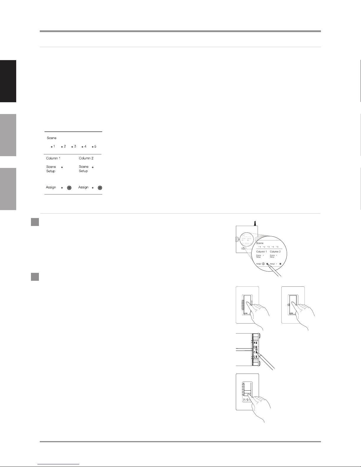
The Integrated scene controller has four internal columns (Columns 1,
2, 3, and 4) that can be programmed like keypad columns. Third-party
devices can access these internal keypads to control RadioRA-SR
devices. These internal keypads are accessible through integration
commands explained in the Protocol section starting on page 16.
The front of the Integrated Scene Controller is shown on the left. Use
the steps below to program Columns 1 and 2. To program Columns 3
and 4, see Advanced programming on page 27.
rd
party
Français
Assigning devices to the Integrated Scene Controller
1. Enter assign mode on the Integrated Scene Controller by
pressing and holding the Assign button of column 1 or 2 until the
column’s Assign LED flashes rapidly (approximately 3 seconds).
When the LED flashes once per second, the column is in assign
mode.
2. Assign devices to the Integrated Scene Controller column
a. Assign dimmers / switches – press and hold the tapswitch
b. Assign window treatments – press any button on the window
on the device until the LED(s) on the device flash and the load
flashes 3 times (approximately 6 seconds). The LED(s) on
assigned dimmers / switches will continue to flash while in assign
mode.
treatment drive and the green LED will flash.
c. Assign keypad columns – press and hold the bottom button
of the column until the LEDs blink (approximately 6 seconds).
Complete the Assigning devices to a keypad section, starting
on page 5, before assigning the keypad to the Integrated Scene
Controller. The LED(s) on assigned keypads will continue to blink
while the Integrated Scene Controller is in assign mode.
12 | Lutron
24/7 Technical Support—800.523.9466
24/7 Technical Support—800.523.9466
Page 15

Integration
Assigning devices to the Integrated Scene Controller (continued)
3. Exit assign mode by pressing and holding the Assign button on
the selected column until the column’s Assign LED stops flashing
and is off (approximately 3 seconds).
About adjusting default levels / positions from an Integrated
Scene Controller
When the Assign button for Column 1 or 2 is pressed or when a command is sent through RS232
or Ethernet to the Integrated Scene Controller, all of the assigned devices go to a default level or
position. The default levels or positions of the devices assigned to an Integrated Scene Controller
column can be customized by using the steps below. All other keypad columns or Integrated
Scene Controller columns that have those devices assigned to them will access the same, newly
customized levels or positions. The column to be adjusted on the Integrated Scene Controller must
already have all zone controls, window treatments, and keypads in the system assigned to it.
English
Español
Français
Adjusting default levels / positions from an Integrated Scene
Controller
1. The Integrated Scene Controller must not be in assign mode before
entering scene setup mode. The Scene Setup and Assign LEDs
should be off. If they are not, press and hold the Assign button until
the LEDs stop flashing (approximately 3 seconds).
2. Enter scene setup mode on the Integrated Scene Controller by
pressing and holding the Assign button on the desired column until
the column’s Scene Setup LED flashes rapidly (approximately 6
seconds).
Note: Pressing and holding the Assign button on the Integrated
Scene Controller for 3 seconds will enter assign mode. Continuing
to hold the Assign button for an additional 3 seconds (6 seconds
total) will enter the scene setup mode.
3. Select the scene to save by tapping (press and release) the
Assign button on the desired column multiple times to cycle
through the Scene LEDs until the LED corresponding to the scene
being programmed turns on solid. This will set the zone controls
and window treatments in the room to the corresponding scene.
Lutron | 13www.lutron.com/radiorasr
Page 16

Integration
Adjusting default levels / positions from an Integrated Scene
Controller
4. Adjust each zone control and window treatment assigned to that
keypad column as follows:
a. Set levels on dimmers – use the tapswitch to adjust the lights
English
b. Set switches – use the tapswitch to adjust the lights to go on
Español
c. Set window treatment position – use the clockwise or
Français
5. Making zone controls and window treatments ‘unaffected’
(optional) – To make assigned devices not respond to a keypad
button press, you may make the devices ‘unaffected’. During
normal operation when you press a keypad button, a device that is
‘unaffected’ will ignore the button press. The light level or window
treatment position will not change. To make devices ‘unaffected’,
follow the corresponding step below based on the type of device
to be made ‘unaffected’.
(continued)
to go on or off. Use the raise or lower button on the right side of
the dimmer to make adjustments to the desired light levels.
or off.
counter-clockwise buttons on the window treatment drive to
adjust the window treatment position.
a. Make a dimmer ‘unaffected’ – if the dimmer is on, press the
tapswitch once to turn it off. After the dimmer is completely
off, hold the lower rocker until the three middle LEDs flash
(approximately 6 seconds), signifying that the next level save will
be ignored. **
b. Make a switch ‘unaffected’ – if the switch is on, turn it off
using the tapswitch. Pull the FASS
the tapswitch. While still holding the tapswitch, push the FASS
switch in. Continue holding the tapswitch until the LED flashes,
signifying that the next level save will be ignored. **
** After a device becomes ‘unaffected’, you have 10 minutes
to complete the level save for all zone controls and window
treatments.
14 | Lutron
TM switch out. Press and hold
24/7 Technical Support—800.523.9466
24/7 Technical Support—800.523.9466
Page 17

Integration
Adjusting default levels / positions from an Integrated Scene
Controller
d. Make a window treatment ‘unaffected’ – if the window
treatment is open, close it using either the clockwise or counterclockwise button. Release the button. After the window
treatment is closed, press and hold the same button used to
close the window treatment until the green LED blinks quickly
(approximately 10 seconds), signifying that the next position
save will be ignored. **
6. Save the levels by pressing and holding the column’s Assign
button until the Scene LED turns off to indicate that the scene
levels have been saved (approximately 3 seconds).
7. Exit scene setup mode on the Integrated Scene Controller by
pressing and holding the Assign button of the selected column
until the column’s Scene Setup LED stops flashing and turns off
(approximately 6 seconds).
(continued)
English
Español
Français
8. Confirm scene setup by tapping (press and release) the Assign
button several times until the LED next to the desired scene turns
on to confirm which scene will be activated. All of the assigned
devices should go to the appropriate levels or positions for that
scene.
** After a device becomes ‘unaffected’, you have 10 minutes to complete the level save for all zone
controls and window treatments.
Note: To change the ‘unaffected’ status of a zone control or window treatment, follow steps 1-4, 6,
and 7 in Adjusting default levels/positions from an Integrated Scene Controller starting on
page 13.
Lutron | 15www.lutron.com/radiorasr
Page 18

12345
6789
87654321
Integration
Protocol
Basics
Connection Information
The Integrated Scene Controller provides both RS232 and Ethernet connections to communicate
with external equipment.
English
Español
Français
RS232
The RS232 connection has the following communication settings:
Baud rate - 38400 (default)•
Data bits - 8•
No parity bit•
1 stop bit•
No flow control / handshaking•
Ethernet
Configuring the Integrated Scene Controller to communicate over a network takes not only
knowledge of the RadioRA
knowledge are advised to contact a networking professional before attempting to connect to the
Integrated Scene Controller over a network. The information below will help an installer communicate
the Integrated Scene Controller configurations to a network professional. The network professional
can make any necessary changes to the networking equipment.
®-SR system, but of networking as well. Installers with limited networking
The installer will make any necessary changes to the Integrated Scene Controller using the setup
command or Device IP program. The Device IP program will allow the installer to detect the
Integrated Scene Controller that is either directly connected to a computer or on the same network.
The installer will be able to see and change the IP address of the Integrated Scene Controller. The
Device IP program is available on the RadioRA Resource Site at http://resi.lutron.com/radiora.
After entering the address into your web browser, you will be prompted to log in or register (if this
is your first time accessing the site). Registration is quick and easy, and you will have immediate
access once registered. After you are logged in, go to the Support menu and select Device IP.
Follow the instructions posted to download and set up the Device IP program.
Single Ethernet port
IEEE 802.3 Auto-Sensing •
10BaseT / 100BaseTX
Supports MDI/MDIX auto-crossover •
(no crossover cable needed)
Female 8P8C “Computer RJ-45” •
socket
Green Connect LED, Amber Activity •
LED
Use Cat 5 cabling or better•
Protocols Used
TCP, UDP, IP, ARP, ICMP, TELNET•
TCP / IP Settings
IP Address: 192.168.250.1 (default) •
Subnet: 255.255.0.0 •
Gateway: 0.0.0.0•
16 | Lutron
24/7 Technical Support—800.523.9466
24/7 Technical Support—800.523.9466
Page 19

Integration
Protocol
Basics (continued)
Telnet Server
Used by third party equipment (i.e. universal remote control)•
Limited to transferring 7bit ASCII characters•
Telnet Port number is 23•
The login name is ‘nwk’•
There is no password•
UDP Multicast Messaging
Used by the Device IP tool during device configuration•
There are no user modifiable settings for UDP messaging•
Rate Limiting
To ensure that the Integrated Scene Controller processes all commands and queries correctly, the
integration device must adhere to the following:
a. Two-way devices should only send a command after receiving a prompt from the Integrated Scene
Controller.
b. One-way devices that cannot detect the prompt should only send one command every second.
English
Español
Français
Note: A raise command followed by a stopraise command, or a lower command followed by a
stoplower command, are considered one command when used together.
Integration Operations
The Lutron® integration protocol allows third-party equipment, such as universal remote controls and
software applications, to control, monitor, and query a RadioRA
The protocol supports three basic types of integration operations in a RadioRA-SR system:
Command — executes an action•
Query• — requests the current status
Monitor• — returns responses
Note: Please see Table of integration operations on page 29 for a list of available integration
operations in a RadioRA-SR system.
®-SR system.
Operation Characters
To help create and manage the different integration operations, three distinct operation characters
have been selected to begin each command. All protocol messages will start with one of the
following operation characters:
# Command — executes an action (e.g. turn a dimmer on/off)
? Query — requests the current status of the system (e.g. determine on/off status of a dimmer)
~ Monitor — returns responses from the system when a change has occurred
(e.g. if someone turns on a dimmer locally a response is sent out to indicate the change)
Note to Integrator: Operation characters are not used in any other location in the protocol command
string. Therefore, the driver can search for these characters to determine the start of a new
command string.
Lutron | 17www.lutron.com/radiorasr
Page 20

Integration
Protocol
Basics (continued)
Operation Types
Operation characters will be followed by operation types. The three most common operation types
are setupisc, output and device:
English
Español
Français
Sent to the Integrated Scene Controller
Integration
Operation
Command
Query
Operation
Character
#
?
Operation
Type Explanation Example
Allows control and monitoring of
setupisc
output
device
refresh Lists out current device levels
output
firmwarerev
various settings for the Integrated
Scene Controller
Allows control and monitoring of
device outputs such as zone controls
and window treatments
Allows control and monitoring of
device inputs such as button presses
and releases
Requests device outputs such as
zone controls and window treatments
Request the software revision number
of the Integrated Scene Controller
#setupisc,list prg
#output,12,1,75
#device,12,50,3
#refresh,255,255
?output,12
?rmwarerev
Feedback from the Integrated Scene Controller
~output,12,1,100
~device,12,3,3
~ error,1,(null),
command not found
Monitor
~
output
device
error
Reports the levels of zone controls
and window treatments that are
assigned to the Integrated Scene
Controller
Reports the levels of zone controls
and window treatments in the active
scene on the Integrated Scene
Controller
Reports when an incorrect command
or query is sent to the Integrated
Scene Controller
Operation Structure
The protocol structure of the integration operations is made up of three parts, followed by a carriage
return.
Operation Integration ID Operation-specific Fields
1. The Operation is made up of the operation character and type.
2. The Integration ID is assigned to each device in the system during the integration set up, providing a
unique user-assigned address for each system device. By default the Integration ID of a device is the
serial number found on each device.
3. The Operation-specific Fields contain additional information relevant to the type of operation used.
4. The entire command string must always be followed by a carriage return to execute the operation.
18 | Lutron
24/7 Technical Support—800.523.9466
24/7 Technical Support—800.523.9466
Page 21

Integration
Protocol
Communication setup
The commands in this section will help the integrator set up communication parameters of the
Integrated Scene Controller through the link. Many of these commands require a power cycle of
the Integrated Scene Controller to take effect. Please follow the directions below carefully. All these
commands may be used over either the RS232 link or the Ethernet link.
Set the communication baud for the RS232 link
The default baud for the RS232 link is 38400. The new baud can be any of the following allowed
rates: 9600/19200/38400/115200. To change the baud use the following command:
#setupisc,rs232 baud,<new baud>
Example:
To set the RS232 baud to 9600 use the following command.
#setupisc,rs232 baud,9600
Note: Cycle power to the device after sending this command for the settings to take effect.
Set the network parameters for the Ethernet/IP link
English
Español
Français
By default the device leaves the factory with the following network settings:
IP address: 192.168.250.1
IP netmask: 255.255.0.0
IP gateway: 0.0.0.0
Use the following command to modify these parameters:
#setupisc,ethernet ip,<ip address>,<ip netmask>,<ip gateway>
Example:
To set the IP address of the device to 192.168.2.1, netmask to 255.255.255.0 and gateway to
0.0.0.0 use the following command.
#setupisc,ethernet ip,192.168.2.1,255.255.255.0,0.0.0.0
Note: The IP address, netmask, and gateway parameter fields must be entered every time, even if
only one parameter is being changed.
Note: Cycle power to the device after sending this command for the settings to take effect.
Note: The network parameters can also be changed by using the DeviceIP tool explained in the
Ethernet section on page 16.
Reset the Integrated Scene Controller over the link
Use this command to force a reset over the communication link.
#setupisc,reset,IREALLYWANTTO
Note: To prevent loss of configuration data, do not reset or cycle power to the Integrated Scene
Controller while it is in assign mode.
Lutron | 19www.lutron.com/radiorasr
Page 22

English
Integration
Protocol
Verify assignments and set up Integration IDs
The commands in this section will help the integrator verify the assigns to the columns in the
Integrated Scene Controller and change the Integration IDs of devices that can be controlled and
monitored. An Integration ID is a unique, user-defined number that identifies a device within a
system.
List the current devices assigned to the Integrated Scene Controller
This command allows the integrator to list the devices assigned to the Integrated Scene Controller
for diagnostic and archival purposes.
#setupisc,list prg
Español
Français
Note: This command will list the zone controls, keypads, and window treatments assigned, the
Integration IDs and the Columns the devices are assigned to. For each assigned device, it lists a
parameter known as the component number. In a device with more than one zone, each zone will be
assigned a unique component number. You will only use this number if you modify the integration ID
of an output assigned to a zone.
Example:
#setupisc,list prg
-Column---Type-------
1 0 (Scene)
2 0 (Scene)
3 0 (Scene)
4 0 (Scene)
-Integration Id--Serial Number--Component--Type------Column--Property Number-
0000417714180 0000417714180 3 Zone 1 00
0000417702151 0000417702151 3 Zone 1 01
0000417682215 0000417682215 3 Zone 1 02
0000420994225 0000420994225 3 Zone 1 03
0000417701141 0000417701141 3 Zone 1 04
0000417700131 0000417700131 0 Control 1
Total Devices:6, Total Load Devices:5
20 | Lutron
24/7 Technical Support—800.523.9466
24/7 Technical Support—800.523.9466
Page 23

Integration
Protocol
Verify assigns and set up Integration IDs (continued)
Change the integration ID of a zone that is assigned to the Integrated Scene
Controller
Each zone control, keypad and window treatment that is assigned to the Integrated Scene Controller
is given an Integration ID which, by default, is the serial number.
This command allows the integrator to change the Integration IDs of zone controls and window
treatments assigned to the Integrated Scene Controller. This is strongly recommended because it
is easier and faster to enter the Integration ID of a zone control or window treatment than the serial
number, and limits the amount of typing errors. Please see the Integration ID worksheet below to
track the Integration ID and serial number of each zone control and window treatment and which
column of the Integrated Scene Controller they are assigned to.
#setupisc,set id,<serial number>,<component number>,<new Integration ID>
Example:
To set the Integration ID of a zone control (component 3) to 12 when the serial number is
0000123456789, use the following command. The zone control must be assigned to the Integrated
Scene Controller before you can change the Integration ID. If you unassign a device, the Integration
ID of the device will revert back to its serial number.
English
Español
Français
#setupisc,set id,0000123456789,3,12
Integration ID Worksheet
Integration ID Serial Number
Example:
0000000000012 0000123456789
Integrated Scene Controller Column
1 2 3 4
4 4
Lutron | 21www.lutron.com/radiorasr
Page 24

1. Send commands directly to each zone control or window treatment. While this method affords
English
2. Send commands to the Integrated Scene Controller, which in turn will select scenes in the room. This
Español
Integration
Protocol
Control / Command
There are two ways to adjust the levels of zone controls and positions of window treatments in the
space:
maximum control in a space, it is harder to set up and it will stagger the action if multiple zone
controls or window treatments are being adjusted at the same time.
method is easiest to set up and all zone controls and window treatments will respond to commands
at the same time. See the Rate Limiting section on page 17.
Send commands directly to zone controls and window treatments in the room
To directly control an output device, the integrator must know the Integration ID of each device that is
to be controlled. The Integration ID is either the user-defined number in the table on page 21, or the
unique serial number that can be found on a label on the back of each device. The serial number of
a device assigned to the Integrated Scene Controller can also be found by following the procedure in
the List the current devices assigned to the Integrated Scene Controller section on page 20.
Use the command string below to send zone controls and window treatments assigned to the
Français
Integrated Scene Controller to a specified scene or to raise / lower the current levels / positions.
#output,<Integration ID>,<command>,<action>
Operation Command Action
Set level 1 Level (0% to 100%) (required)
Start raise 2 —
Start lower 3 —
Stop raise / lower 4 —
Examples:
Send zone control or window treatment with Integration ID 12 to 75% with a fade time of 10 seconds
and no delay.
#output,12,1,75,10
Send zone control or window treatment with Integration ID 12 to 50% with a fade time of 2 seconds
and 1 second delay.
#output,12,1,50,2,1
Fade time in seconds (max 600, default 2) (optional)
Delay time in seconds (max 600, default 0) (optional)
22 | Lutron
24/7 Technical Support—800.523.9466
24/7 Technical Support—800.523.9466
Page 25

Integration
Protocol
Control / Command (continued)
Send commands to the Integrated Scene Controller to select a scene
Use the following command to select scenes by simulating button presses on the Integrated Scene
Controller. After the action is complete, the Integrated Scene Controller will retrieve the levels of
devices assigned to it and report the levels using the monitoring commands.
#device,<Integration ID>,<component number>,<command>
Note: For proper system operation, a start raise/lower command must be followed by a stop
raise / lower command sent to the same integration ID. Otherwise, the zone controls will raise to
100% / open or lower to low end / closed.
Note: Component numbers 0 (Column 1), 20 (Column 2), 40 (Column 3) and 60 (Column 4) are
special numbers that are only used by the Integrated Scene Controller to report that no scene is
currently active in the corresponding column.
Command Action
3 Press
4 Release
English
Español
Français
Scene Component Number
Column 1 Column 2 Column 3 Column 4
1 1 21 41 61
2 2 22 42 62
3 3 23 43 63
4 4 24 44 64
5 5 25 45 65
6 6 26 46 66
7 7 27 47 67
8 8 28 48 68
9 9 29 49 69
10 10 30 50 70
11 11 21 51 71
12 12 32 52 72
13 13 33 53 73
14 14 34 54 74
15 15 35 55 75
16 16 36 56 76
17 (OFF) 17 37 57 77
Raise Button 18 38 58 78
Lower Button 19 39 59 79
No scene (for
monitoring
only)
0 20 40 60
Lutron | 23www.lutron.com/radiorasr
Page 26

Integration
Protocol
Control / Command (continued)
Examples:
Select Scene 3 in the group of devices associated with Column 1.
English
#device,12,3,3
Select Scene 3 in the group of devices associated with Column 4.
#device,12,63,3
Select Scene 0 (OFF) in the group of devices associated with Column 3.
#device,12,57,3
Start raising the group of devices associated with Column 2.
Español
#device,12,38,3
Stop raising the group of devices associated with Column 2.
#device,12,38,4
Listing out current device levels
Français
The current levels of devices assigned to the Integrated Scene Controller can be listed out by using
the following command:
#refresh,255,255
Query
The current status of devices within a RadioRA-SR system can be requested through the Integrated
Scene Controller.
Request device outputs
The device outputs for zone controls and window treatments can be requested using the command
below:
?output,<Integration ID>,1
Example:
To request the output of a device with an Integration ID of 12:
?output,12,1
Request the software revision of the Integrated Scene Controller
The software revision of the Integrated Scene Controller can be requested using the command
below:
?rmwarerev
Example:
?rmwarerev
~FIRMWAREREV,1.9 [Release]
~FIRMWAREDATE,April 06 2009 14:22:54
24 | Lutron
24/7 Technical Support—800.523.9466
24/7 Technical Support—800.523.9466
Page 27

Integration
Protocol
Monitor
A touchscreen may use the following feedback to represent the state of a RadioRA®-SR system to
the user:
1. After a command is issued to the system through the Integrated Scene Controller, it will report the
target levels of devices assigned to it.
2. When a zone control or window treatment is modified locally (using buttons on the zone control or
window treatment), the new level will be reported.
3. After a button is pressed on an assigned keypad, the Integrated Scene Controller will report the
target levels of all zone controls and window treatments in the system and it will report the scene
selected on the keypad.
Note: In the Monitor section of this guide, the Integration ID refers to the Integration ID of the
Integrated Scene Controller, which is also its serial number. The serial number of the Integrated
Scene Controller can be found on the back of the device.
Using the levels of zone controls and window treatments reported by the
Integrated Scene Controller
English
Español
Français
For the convenience of the integrator, zone control and window treatment levels are reported using
the same command format that is provided to control them individually.
~output,<Integration ID>,1,<target level>
Examples:
When the tapswitch of a dimmer (with Integration ID 12) is pressed to turn off the dimmer, the
following is reported:
~output,12,1,0
When a dimmer (with Integration ID 12) is raised to full on, the following is reported:
~output,12,1,100
When a scene is activated through the Integrated Scene Controller to set a dimmer (with Integration
ID 12) to 50%, a dimmer (with Integration ID 13) to 100% and a shade (with Integration ID 14) to
25%, the following will be reported:
~output,12,1,50
~output,13,1,100
~output,14,1,25
Note: Since this is a two-way system, any zone control or window treatment that is powered down
will not report a level.
Note: The Integrated Scene Controller always reports the target level, which is the level that the zone
controls or window treatments will go to at the end of the fade and delay time.
Lutron | 25www.lutron.com/radiorasr
Page 28

English
Español
Integration
Protocol
Monitor (continued)
Using the scene information reported by the Integrated Scene Controller
For the convenience of the integrator, scene selections within a group of devices are reported from
the Integrated Scene Controller using the same command format that is provided to activate them
through the Integrated Scene Controller.
~device,<Integration ID>,<component number>,3
Use the table on page 23 to determine which button was selected in which column of the Integrated
Scene Controller.
The Integration ID reported is the Integration ID of the keypad that sent the command or the zone
control or window treatment whose local level change invalidated the current scene.
Examples:
When Scene 3 is pressed on a keypad with an Integration ID of 12 (which is assigned to column 1
of the Integrated Scene Controller), the following is reported to indicate that Scene 3 is active for
devices assigned to Column 1:
~device,12,3,3
Français
When Scene 3 is pressed on a keypad with an Integration ID of 12 (which is assigned to column 3
of the Integrated Scene Controller), the following is reported to indicate that Scene 3 is active for
devices assigned to Column 3:
~device,12,43,3
When the tapswitch of a dimmer with an Integration ID of 12 is pressed to turn off the dimmer (which
is assigned to column 1 of the Integrated Scene Controller), the following is reported to indicate that
there is no active scene for column 1:
~device,12,0,3
Error reporting
If the Integrated Scene Controller does not understand an integration string command or query,
it generates an ~error response. String processing stops after one bad argument, so errors will
only come from the first bad argument in the string. The Error commands evaluate syntax only; they
are not returned for valid commands sent to bad integration ID numbers, incorrect components,
or incorrect component/action combinations. The description field will be helpful in diagnosing and
troubleshooting problems.
All errors are formatted as follows:
~error,<bad token number>,<bad token string>,<description>
Example:
~error,1,(null),command not found
26 | Lutron
24/7 Technical Support—800.523.9466
24/7 Technical Support—800.523.9466
Page 29

Integration
Protocol
Advanced programming
The commands in this section are used to set up the Integrated Scene Controller using the link.
These commands allow you to do the following:
1. Enter assign mode to assign zone controls, window treatments, and keypads to Columns 3 or 4,
since this is not possible using the buttons on the front of the Integrated Scene Controller.
2. Exit assign mode.
3. Assign Column 3 or 4 to a keypad that is in assign mode.
4. Save the current levels of zone controls and window treatments associated with Column 3 or 4 to a
selected scene.
Note: These commands will also work for Columns 1 and 2, as an alternative to pressing buttons on
the front of the Integrated Scene Controller.
English
Español
Enter assign mode for Column 3 or 4
This command will allow you to enter assign mode for Column 3 or 4 to assign zone controls and
window treatments using the link.
#setupisc,begin prg,<column number 3 or 4>
Example:
To enter assign mode for Column 3 on the Integrated Scene Controller:
#setupisc,begin prg,3
Note: You must now walk around and assign all zone controls and window treatments to this column
according to step 2 of the Assigning devices to the Integrated Scene Controller section on
page 12.
Exit assign mode for Column 3 or 4
This command will allow you to exit the assign mode of column 3 and 4 using the link.
#setupisc,end prg,<column number 3 or 4>
Example:
To exit assign mode for Column 3 on the Integrated Scene Controller:
#setupisc,end prg,3
Note: You must exit using the same column number you used to enter assign mode.
Français
Assign Column 3 or 4 to a keypad that is in assign mode
This command will allow you to assign column 3 or 4 on the Integrated Scene Controller to a keypad
that is in assign mode. This will allow the Integrated Scene Controller to recognize button presses
that originate on this keypad.
#setupisc,assign col,<column number 3 or 4>
Example:
To assign Column 3 on the Integrated Scene Controller to a keypad:
#setupisc,assign col,3
Note: The keypad that you want to assign the Integrated Scene Controller Column to must already
be in assign mode.
Lutron | 27www.lutron.com/radiorasr
Page 30

English
Integration
Protocol
Advanced programming (continued)
Save levels of devices to a scene button
This command will allow you to save the current levels of zone controls and window treatments
to any scene button on an Integrated Scene Controller column (see the table on page 23 for a
list of programmable buttons on the Integrated Scene Controller and their associated component
numbers). First, complete step 4 in the Adjusting default levels/positions from an Integrated
Scene Controller section on page 14. Then, execute the save command string below:
#setupisc,scene save,<button number>
Example:
Español
Français
To save the current levels/positions of zone controls and window treatments to button number 41
which is on Column 3 of the Integrated Scene Controller:
#setupisc,scene save,41
Note: The command will only work on zone controls and window treatments that are assigned to the
Integrated Scene Controller column that contains the button to be saved.
List the IP address, Subnet Mask, and Gateway settings of the Integrated Scene
Controller
This command allows the integrator to list the IP address, Subnet Mask, and Gateway settings of the
Integrated Scene Controller.
#setupisc,list ip
List the RS232 settings of the Integrated Scene Controller
This command allows the integrator to list the RS232 settings of the Integrated Scene Controller.
#setupisc,list 232
28 | Lutron
24/7 Technical Support—800.523.9466
24/7 Technical Support—800.523.9466
Page 31

Integration
#output,12,1,75,10
#device,1,3,3
#refresh,255,255
#setupisc,reset,IREALLYWANTTO
#setupisc,set id,0000123456789,3,12
Protocol: Table of integration operations
#setupisc,begin prg,3
#setupisc,end prg,3
#setupisc,assign col,3
#setupisc,col type,0
#setupisc,scene save,41
#setupisc,rs232 baud,9600
~output,12,1,100
?output,12,1
#setupisc,ethernet ip,192.168.2.1,255.255.255.0,0.0.0.0
#setupisc,list prg
#setupisc,list ip
#setupisc,list 232
#refresh,255,255
?rmwarerev
~device,12,3,3
English
Español
Français
~error,1,(null),command not found
treatments in the room.
select a scene.
known levels.
Command (sent to the Integrated Scene Controller)
String Action Example
#output,<Integration ID>,<command>,<action> Send commands directly to zone controls and window
#device,1,<component number>,<command> Send commands to the Integrated Scene Controller to
#refresh,255,255 Request the Integrated Scene Controller to report current
Integrated Scene Controller.
#setupisc,reset,IREALLYWANTTO Restart the Integrated Scene Controller over the link.
#setupisc,set id,<serial number>,<component number>,<new Integration ID> Change the Integration ID of a device that is assigned to the
#setupisc,begin prg,<column number 1, 2, 3 or 4> Enter assign mode for Column 3 or 4.
#setupisc,end prg,<column number 1, 2, 3 or 4> Exit assign mode for Column 3 or 4.
Scene Controller.
#setupisc,assign col,<column number 3 or 4> Assign Column 3 or 4 to a keypad.
#setupisc,col type,<column type 0 or 1> 0: Scene 1: Preset Set up the column to use scenes or shade presets.
#setupisc,scene save,<button number> Save levels of devices to a scene button on the Integrated
#setupisc,rs232 baud,<new baud> Set the communication baud for the RS232 link.
Controller.
the Integrated Scene Controller.
#setupisc,ethernet ip,<ip address>,<ip netmask>,<ip gateway> Set the network parameters for the Ethernet/IP link.
#setupisc,list prg List the current devices assigned to the Integrated Scene
#setupisc,list ip List the IP address, Subnet Mask, and Gateway settings of
#setupisc,list 232 List the RS232 settings of the Integrated Scene Controller.
#refresh,255,255 List out current device levels.
Query (sent to the Integrated Scene Controller)
treatments
String Action Example
?output,<Integration ID>,1 Request device outputs such as zone controls and window
Integrated Scene Controller.
?firmwarerev Requests the latest software revision number of the
Monitor (received from the Integrated Scene Controller)
String Definition Example
initiated that scene.
~output,<Integration ID>,1,<target level> Reports the levels of zone controls and window treatments.
~device,<Integration ID>,<component number>,3 Reports which scene was selected and which device
~error,<bad token number>,<bad token string>,<description> Reports errors in a string command.
Text within angle brackets “<text>” identifies that the text is a variable which is different for each system and circumstance.
Note: The entire command string must always be followed by a carriage return to execute the operation.
Lutron | 29www.lutron.com/radiorasr
Page 32

Resetting devices to factory settings
About resetting devices to factory settings
Resetting devices to factory settings will remove them from the system and will clear all
programming. After being returned to factory settings, the devices will need to be reprogrammed as
part of a RadioRA
®-SR system. To reset a device to factory settings, perform the steps below.
English
Español
Reset zone controls to factory settings
1. Triple tap and hold the tapswitch on a zone control. DO NOT
release the button after the third tap.
2. Keep the button pressed on the third tap until the status LEDs start
to scroll up and down quickly (approximately 3 seconds).
3. Release the button and immediately triple tap it again. The status
LEDs will scroll up and down slowly. When the LEDs stop scrolling,
the device has been returned to factory settings.
Reset keypads to factory settings
Français
1. Triple tap and hold any scene button on a keypad. DO NOT release
the button after the third tap.
2. Keep the button pressed on the third tap until all the LEDs start to
flash slowly (approximately 3 seconds).
3. Release the button and immediately triple tap it again. The status
LEDs will flash quickly. When the LEDs stop flashing, the device
has been returned to factory settings.
3X
+
hold
3X
+
hold
3X
3X
Reset PicoTM wireless controls to factory settings
1. Triple tap and hold either the top or bottom button on a Pico
wireless control. DO NOT release the button after the third tap.
2. Keep the button pressed on the third tap until the LED next to the
top button turns on solid (approximately 3 seconds).
3. Release the button and immediately triple tap it again. The LED
next to the top button will flash quickly. When the LED stops
flashing, the device has been returned to factory settings.
30 | Lutron
3X
+
hold
24/7 Technical Support—800.523.9466
24/7 Technical Support—800.523.9466
3X
Page 33

Resetting devices to factory settings
Reset sensors to factory settings
1. Triple tap and hold either the Lights On or Lights Off button on a
sensor. DO NOT release the button after the third tap.
2. Keep the button pressed on the third tap until the sensor lens
starts to flash quickly (approximately 3 seconds).
3X
3. Release the button and immediately triple tap it again. The sensor
lens will flash slowly. When the lens stops flashing, the sensor has
been returned to factory settings.
Reset Integrated Scene Controller to factory settings
1. Remove power from the Integrated Scene Controller by unplugging
the power supply cord.
2. Press and hold the Assign button for either Column 1 or 2 before
returning power to the Integrated Scene Controller. Plug the power
supply cord back in and continue to hold the Assign button until
both Assign LEDs continuously flash red.
+
hold
English
3X
Español
Français
3. Release the Assign button. Then press and release it again.
4. The Integrated Scene Controller will take several seconds to reset.
All LEDs will flash red once, and the green Scene LEDs will turn on
for 3 seconds. When the green LEDs turn off, reset is complete.
Reset window treatments to factory settings
1. Press and hold the close limit button ( ) on the window treatment
drive for 5 seconds. The green LED on the drive will flash quickly
for 2 seconds and then stay on.
2. Press and hold the open limit button (
LED on the drive will flash and then stay on.
3. Press and hold the clockwise button (
LED will flash and then stay on.
4. Press and hold the counter-clockwise button (
LED will flash blue briefly and the window treatment drive will now
reset to factory settings.
) for 5 seconds. The green
) for 5 seconds. The green
) for 5 seconds. The
Note: Resetting a window treatment to factory settings will clear
out any assignments to keypads, but will not affect the close or
open limits of the window treatment.
Lutron | 31www.lutron.com/radiorasr
Page 34

Programming worksheets
Programming worksheets (make copies as needed)
Keypad Type:
Location:
Serial Number:
English
Scene Engraving
Español
Français
1
2
3
4
5
6
7
Raise/Lower Always raises/lowers lights while being
Keypad Type:
Location:
Serial Number:
Zones
1 2 3 4 5 6
pressed
Scene Engraving
1
2
3
4
5
6
7
Raise/Lower Always raises/lowers lights while being
32 | Lutron
Zones
1 2 3 4 5 6
pressed
24/7 Technical Support—800.523.9466
24/7 Technical Support—800.523.9466
Page 35

Troubleshooting
Troubleshooting guide
Symptom Possible Cause Remedy
Dimmers do not dim
Switches do not turn on or off
LEDs on dimmers or switches
are not lit
A zone control or window
treatment will not assign to a
keypad
Keypad buttons do not send
lights or shades / drapes to the
correct level or position
Keypad buttons do not activate
lights or shades / drapes
Integrated Scene Controller is
not responding to commands
Dimmer load does not flash
when assigned to keypad or
Integrated Scene Controller
Lamp is burned out. Replace lamp.
TM is pulled out. Push FASS in.
FASS
Power is turned off. Turn circuit breaker on.
Devices are too far from each
other.
System is programmed
incorrectly.
Network parameters are not
set up correctly.
Integrated Scene Controller is
not plugged in.
Command strings are
incorrect.
Compact fluorescent load. Verify that the compact
Devices are too far from each
other.
Make sure that all RadioRA
devices, except remote dimmers
(SD-RD) and remote switches
(SD-RS), are within 30 ft (9m) of
each other.
Program the keypads according
to the Programming keypads
section starting on page 5.
Check IP address, telnet
settings, or RS232 connections
settings.
Plug in Integrated Scene
Controller.
Verify that the command string
matches the desired string
in the Table of integration
operations on page 29.
fluorescent load is dimmable.
Use the LEDs on the dimmer as
an indicator that it is assigned.
Make sure that all RadioRA-SR
devices, except remote dimmers
(SD-RD) and remote switches
(SD-RS), are within
30 ft (9m) of each other.
®-SR
English
Español
Français
Lutron | 33www.lutron.com/radiorasr
Page 36

English
Español
Contact Lutron
Contact information
Internet: www.lutron.com/radiorasr
E-mail: product@lutron.com
World Headquarters
USA
Lutron Electronics Co., Inc.
7200 Suter Road
Coopersburg, PA 18036-1299
TEL +1.610.282.3800
FAX +1.610.282.1243
Toll-Free 1.888.LUTRON1
Technical Support 1.800.523.9466
North and South America Technical Hotlines
USA, Canada, Caribbean: 1.800.523.9466
Mexico: +1.888.235.2910
Central / South America: +1.610.282.6701
Français
These products may be covered under one or more of the following U.S. Patents: 5,248,919; 5,399,940; 5,637,930;
5,838,226; 5,848,054; 5,905,442; 5,982,103; 6,169,377; 6,380,696; 6,687,487; 6,803,728; 6,935,403; 6,994,145;
7,071,634; 7,166,970; 7,281,565; 7,362,285; 7,365,282; 7,382,100; 7,408,525; D439,220; D453,742; D456,783; D461,782;
D465,460; D554,071; D554,072; D554,073; and corresponding foreign patents. U.S. and foreign patents pending.
HomeLogic and ELAN are registered trademarks of ELAN Home Systems, LLC, Lexington, Kentucky. NetStreams is a
registered trademark of NetStreams, LLC., Austin, Texas. Universal Electronics is a registered trademark of Universal
Electronics, Cypress, California. Life|ware is a trademark of Exceptional Innovation, Westerville, Ohio. Philips is a registered
trademark of Koninklijke Philips Electronics N.V., Eindhoven, the Netherlands. RadioRA, Sivoia, Lutron and the Sunburst
logo are registered trademarks and FASS and Pico are trademarks of Lutron Electronics Co., Inc.
© 2009 Lutron Electronics Co., Inc.
Made and printed in the U.S.A. 06/2009 P/N 044-155 Rev. D
 Loading...