


Setup Guide
A Step-by-Step Guide for Programming and Operating a
Complete Lutron RadioRA® Wireless Central Home
Lighting Control System
®
Note: Please leave this manual with homeowner.
Important Application Notes
1. It is recommended that only one GRAFIK Eye
® Control Units may be wired (linked) to the same GRAFIK Eye® Interface, however, all GRAFIK Eye® Control Units on
Eye
that link will respond in unison to the commands from the GRAFIK Eye
the same Interface will carry out ALL commands from the GRAFIK Eye
OFF, etc...). Interface commands cannot be sent to one individual GRAFIK Eye
® Control Units.
Eye
• This application may be desired if multiple GRAFIK Eye
the same scene be selected on each GRAFIK Eye
not
• Lutron does
recommend using one GRAFIK Eye® Interface to linked GRAFIK Eye® Control Units located in more
® Control Unit be wired to each GRAFIK Eye® Interface. Multiple GRAFIK
® Interface. ALL GRAFIK Eye® Control Units wired to
® Interface (i.e. go to GRAFIK Eye® scene 3, Turn
® Control Unit on a link of multiple GRAFIK
® Control Units are in the same room and it is intended that
® Control Unit simultaneously.
than one room.
2. Scene 1 on a GRAFIK Eye
recommended scene 1 on GRAFIK Eye
3. Setting the light levels for GRAFIK Eye
4. A GRAFIK Eye
® scene may be added to any RadioRA® Master Control button which has been previously programmed
® Control Unit is the default scene for ALL ON, SECURITY, and FLASH MODES. It is
® Control Units be set to full intensity with a fade time of zero seconds.
® scenes should be done prior to any operations in this Setup Guide.
without altering that buttons existing programming.
5. See RadioRA
® Application Note No.48 (P/N 366-730) for steps to activate GRAFIK Eye® scenes 5-16 from a RadioRA®
Master Control.
6. For information on integrating your RadioRA
control, shade motor control, etc... see the RadioRA® Application Notes on our web page at
® system with an astronomic timeclock, photocell, telephone interface, car visor
www.lutron.com/
applicationnotes/index.html.
7. RadioRA® lighting control systems use radio frequency technology for communication. Currently, RadioRA® lighting control
systems are available in two frequencies. To determine the frequency of a RadioRA
® product, examine the model number
on the product’s unit label. The labels are located on the side of all “wallbox” products, and on the bottom of all “tabletop”
products.
The second letter in all RadioRA
® model numbers indicates the product’s frequency. For example: RA-600LM is an “A”
frequency product, whereas RB-600LM is a “B” frequency product.
Note: Do not mix RadioRA
® “A” and “B” frequency products within the same system. Products with different frequencies
are not compatible.
If you have any questions concerning the installation or operation of this product, please call the Lutron Technical Support
Center at 1-800-523-9466.
Consumer Information
This symbol is intended to alert the user to the presence of important installation and operating instructions.
Danger
This RadioRA® system must not be used to control equipment, other than lighting, which is not visible from every master or
local control location. It also must not be used to control equipment which could create hazardous situations such as
entrapment if operated accidentally. Examples of equipment which must not be controlled by this RadioRA
(but are not limited to) motorized gates, garage doors, industrial doors, and microwave ovens, heating pads, etc. It is the
installer's responsibility to ensure that the equipment, other than lighting, being controlled is visible from every master or
local control location and that only suitable equipment is connected to this RadioRA
® system.
FCC Information
NOTE: This equipment has been tested and found to comply with the limits for a Class B digital device, pursuant to part 15 of the FCC rules. These limits are
designed to provide reasonable protection against harmful interference in a residential installation. This equipment generates, uses and can radiate radio
frequency energy and, if not installed and used in accordance with the instructions, may cause harmful interference to radio or television reception, which can
be determined by turning the equipment off and on, the user is encouraged to try to correct the interference by one or more of the following measures:
• Reorient or relocate the receiving antenna.
• Increase the separation between the equipment and receiver.
• Connect the equipment into an outlet on a circuit different from that to which the receiver is connected.
• Consult the dealer or an experienced radio/TV technician for help.
Caution: Changes or modifications not expressly approved by Lutron Electronics Co. could void the user's authority to operate this equipment.
RadioRA® Setup Guide
® system include

Table of Contents
Section 1 - Start-Up
Activating Your System
Activating Repeaters ...................................................................................................................... 1-1
Activating Controls .........................................................................................................................1-3
Programming Preparations
Filling out the System Programming Worksheet .........................................................................1-6
Assigning a Column of Buttons as ROOMS or SCENES ............................................................ 1-7
ROOM Button Programming
Assigning Dimmers, Switches or GRAFIK Eye® Control Units to ROOM Buttons....................1-9
Setting Light Levels/GRAFIK Eye® Scene Selection for ROOM Buttons ...................................1-11
SCENE Button Programming
Assigning Dimmers, Switches or GRAFIK Eye® Control Units to SCENE Buttons ..................1-13
Setting Light Levels/GRAFIK Eye® Scene Selection for SCENE Buttons ..................................1-15
Section 2 - Advanced Features
Advanced Programming
Programming the ALL ON Button..................................................................................................2-1
Programming the ALL OFF Button................................................................................................2-3
Copying Button Programming .......................................................................................................2-5
Erasing Button Programming ........................................................................................................2-7
Section 3 - Expanding Your System
Adding Basic System Components
Adding an Auxiliary Repeater ........................................................................................................3-1
Adding Controls ..............................................................................................................................3-3
Adding a Switch Closure Interface
Activating a Switch Closure Interface ...........................................................................................3-5
Assigning Dimmers, Switches or GRAFIK Eye® Control Units to Input Channels ...................3-7
Setting Light Levels/GRAFIK Eye® Scene Selection for Input Channels ...................................3-10
Section 4 - Troubleshooting
Troubleshooting Guide
Diagnostic Tools
BEEP Mode ......................................................................................................................................4-3
FLASH Mode ....................................................................................................................................4-4
Returning Components to Default Factory Settings
Master Controls ...............................................................................................................................4-5
Switch Closure Interface ................................................................................................................4-6
Dimmers ...........................................................................................................................................4-7
Switches...........................................................................................................................................4-8
GRAFIK Eye® Interface.................................................................................................................... 4-9
Repeaters .........................................................................................................................................4-10
.................................................................................................................4-1
Section 5 - Miscellaneous
Using RadioRA® Master Controls with Raise/Lower
Programming Worksheet
.........................................................5-1
.............................................................................................................5-2
RadioRA® Setup Guide
Activating Your System
?
Activating Repeaters
Repeaters must be in their permanent location and all controls must be operating (dimmers and switches
must be wired to a light) in order to be activated.
Important Notes:
1. If your system has only one Repeater, it must be
assigned as a Main Repeater.
2. If your system has more than one Repeater, only
one
can be assigned as a Main Repeater.
3. If an LED turns orange while activating your
system, a system error occurred, consult the
Troubleshooting Guide.
Read each Step completely before
starting.
Section 1 - Start-Up
Step 1 Assign a Main Repeater
Any Repeater in the system can be the Main
Repeater.
Note: The green AUXILIARY LED will initially be ON
on all Repeaters.
Press and hold the MAIN button until the
green MAIN LED turns ON (approximately 3
seconds).
REPEATER
MAIN
ACTIVATE
REPEATER
VERIFY
BEEP
Step 2 Activate the Main Repeater
Press and hold the ACTIVATE REPEATER
button until the green ACTIVATE REPEATER
LED begins to flash (approximately 3
seconds).
REPEATER
MAIN
AUXILIARY
Green ACTIVATE REPEATER LED will stay
ON when the Repeater has been activated.
REPEATER
MAIN
AUXILIARY
ACTIVATE
REPEATER
CONTROLS
ACTIVATE
REPEATER
CONTROLS
VERIFY
BEEP
FLASH
VERIFY
BEEP
FLASH
1-1
AUXILIARY
CONTROLS
Green MAIN LED is ON.
REPEATER
MAIN
AUXILIARY
ACTIVATE
REPEATER
CONTROLS
RadioRA® Setup Guide
FLASH
VERIFY
BEEP
FLASH
If the ACTIVATE REPEATER LED turns
orange, consult the Troubleshooting Guide,
Section
I or II.
• If you have only one Repeater proceed
to Step 4.
Activating Your System
Repeater
Note: All remaining Repeaters must be Auxiliary
Repeaters (up to 3).
Press and hold the ACTIVATE REPEATER
button until the green ACTIVATE REPEATER
LED begins to flash (approximately 3
seconds).
REPEATER
MAIN
ACTIVATE
REPEATER
VERIFY
BEEP
Step 4 Complete Repeater activationStep 3 Activate each Auxiliary
Press and hold the ACTIVATE REPEATER
button on any Repeater until the green
ACTIVATE REPEATER LED turns OFF
(approximately 3 seconds).
REPEATER
MAIN
AUXILIARY
ACTIVATE
REPEATER
CONTROLS
VERIFY
BEEP
FLASH
AUXILIARY
CONTROLS
FLASH
Green ACTIVATE REPEATER LED will stay
ON when Repeater has been activated.
REPEATER
MAIN
AUXILIARY
ACTIVATE
REPEATER
CONTROLS
VERIFY
BEEP
FLASH
If the ACTIVATE REPEATER LED turns
?
orange, consult the Troubleshooting Guide,
Section
I, II or III.
The green ACTIVATE REPEATER LED on
ALL
Repeaters will turn OFF. The MAIN or
AUXILIARY LED will remain ON.
REPEATER
MAIN
AUXILIARY
ACTIVATE
REPEATER
CONTROLS
VERIFY
BEEP
FLASH
• Repeater activation is now complete.
• Proceed to Activate Controls on page
1-3.
Section 1 - Start-Up
• Repeat Step 3 to activate any remaining
Auxiliary Repeaters.
• Proceed to Step 4 when all Repeaters
have been activated.
RadioRA® Setup Guide
1-2
?
Activating Your System
Activating Controls
Master Controls, Dimmers, Switches, and GRAFIK Eye® Control Units may be activated in any order.
Step 1 Begin Control activation
Press and hold the ACTIVATE CONTROLS
button on
any
Repeater until the green
ACTIVATE CONTROLS LED turns ON
(approximately 3 seconds).
REPEATER
MAIN
AUXILIARY
ACTIVATE
REPEATER
CONTROLS
VERIFY
BEEP
FLASH
Section 1 - Start-Up
The green ACTIVATE CONTROLS LED on
ALL
Repeaters will turn ON.
REPEATER
MAIN
ACTIVATE
REPEATER
VERIFY
BEEP
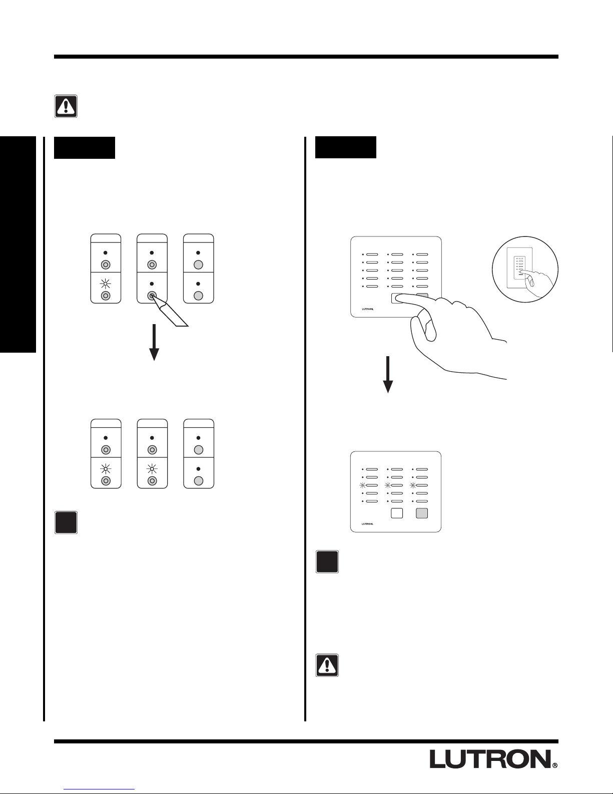
Step 2 Activate a Master Control
Go to any Master Control.
Press any button.
• All LEDs will flutter, then
• Top and bottom row will flash alternately
Tabletop Master Wall Master
Middle row of LEDs will turn ON when Master
Control has been activated.
OR
ALL ON
ALL OFF
AUXILIARY
CONTROLS
FLASH
If the Activate Controls LED fails to turn ON,
?
consult the Troubleshooting Guide, Section
IV.
If a Master Control fails to respond as
described above, consult the Troubleshooting
Guide, Section
VI or VII.
• Repeat Step 2 to activate any remaining
Master Controls.
Activate one Master Control at a time. Wait for
the middle row of LEDs to turn ON before
activating any remaining Master Controls.
• Proceed to Step 3 when all Master
Controls have been activated.
1-3
RadioRA® Setup Guide

Activating Your System
TRON
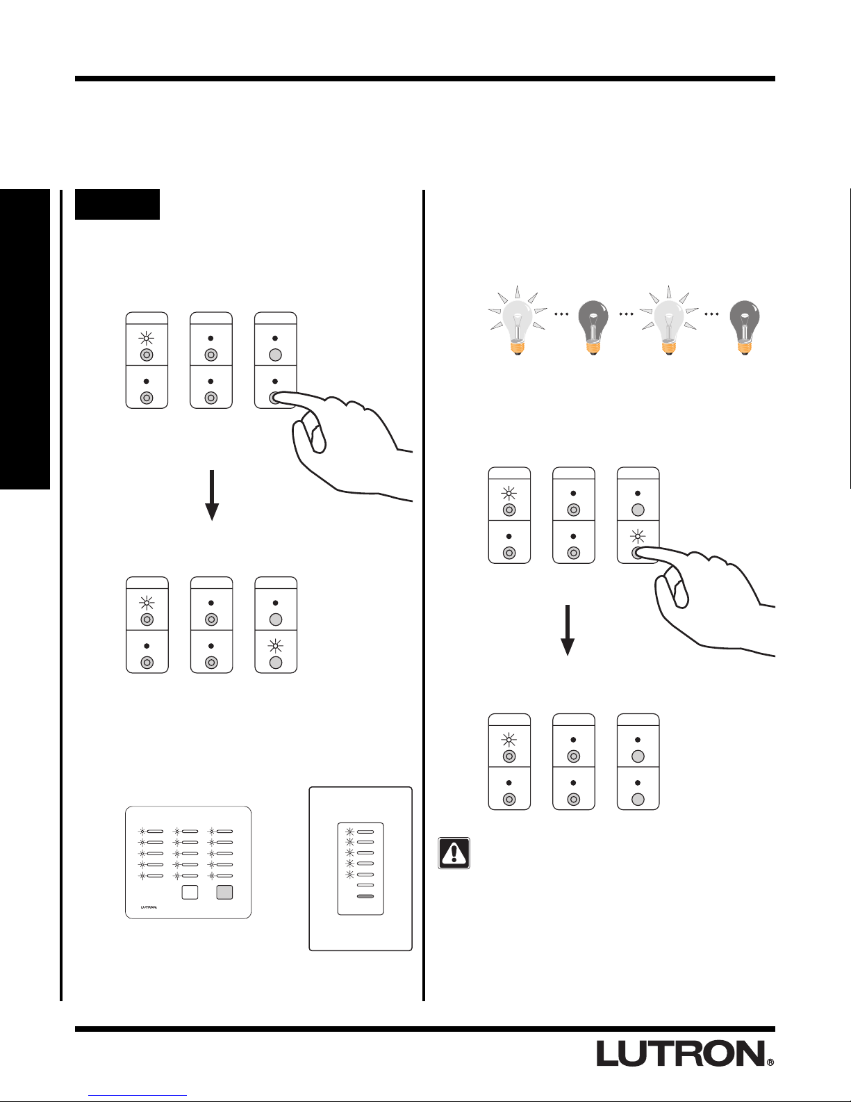
Step 3 Activate a Dimmer, Switch or
GRAFIK Eye
Go to any Dimmer, Switch or GRAFIK Eye
Control Unit. Turn the Dimmer or Switch ON or
OFF by pressing the tapswitch. On a GRAFIK
Eye® Control Unit, change the selected scene
by pressing a scene button.
Dimmer Switch
The light(s) that the Dimmer, Switch or
GRAFIK Eye® Control Unit operate will turn
ON and OFF a few times when it has been
activated.
® Control Unit
®
OR
GRAFIK Eye®
Control Unit
Step 4 Complete Control activation
Press and hold the ACTIVATE CONTROLS
button on any Repeater until the green
ACTIVATE CONTROLS LED turns OFF
(approximately 3 seconds).
REPEATER
MAIN
AUXILIARY
The green ACTIVATE CONTROLS LED on
ALL
Repeaters will turn OFF. The MAIN or
AUXILIARY LED will remain on.
REPEATER
MAIN
AUXILIARY
ACTIVATE
REPEATER
CONTROLS
ACTIVATE
REPEATER
CONTROLS
VERIFY
BEEP
FLASH
VERIFY
BEEP
FLASH
Section 1 - Start-Up
If a Dimmer, Switch or GRAFIK Eye® Control
Unit fails to respond as described above,
?
consult the Troubleshooting Guide, Section
• Repeat Step 3 to activate any remaining
Dimmers, Switches or GRAFIK Eye®
Control Units.
Activate one Dimmer, Switch or GRAFIK Eye®
Control Unit at a time. Wait for the control to
flash its light(s) before activating any remaining
controls.
• Proceed to Step 4 when all Dimmers,
Switches or GRAFIK Eye® Control Units
have been activated.
V.
• Continued on next page.
RadioRA® Setup Guide
1-4
Activating Your System
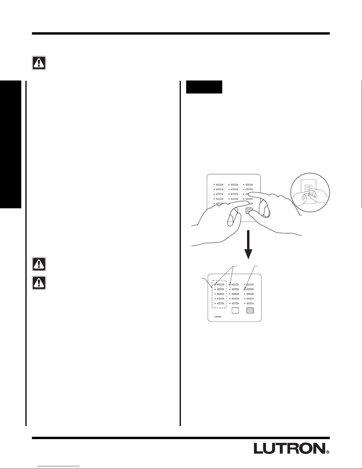
Step 5 Verify that all Controls have
been activated
Press and hold the FLASH button on any
Repeater until the green FLASH LED turns
ON (approximately 3 seconds).
REPEATER
MAIN
AUXILIARY
ACTIVATE
REPEATER
CONTROLS
VERIFY
BEEP
FLASH
Section 1 - Start-Up
Green FLASH LED on all Repeaters will turn
ON.
REPEATER
MAIN
ACTIVATE
REPEATER
VERIFY
BEEP
Dimmers, Switches, and GRAFIK Eye®
Control Units, if activated, will flash the
light(s) they control. Make note of any
Dimmers, Switches or GRAFIK Eye® Control
Units which are not activated.
After verifying that all Master Controls,
Dimmers, Switches, and GRAFIK Eye® Control
Units are activated, press and hold the FLASH
button on any Repeater until the green FLASH
LED turns OFF (approximately 3 seconds).
REPEATER
MAIN
AUXILIARY
ACTIVATE
REPEATER
CONTROLS
VERIFY
BEEP
FLASH
AUXILIARY
CONTROLS
FLASH
Master Controls, if activated, will flash all
their LEDs. Make note of any Master Controls
which are not activated.
Wall Master
Tabletop Master
Green FLASH LED on all Repeaters will turn
OFF.
REPEATER
MAIN
AUXILIARY
ACTIVATE
REPEATER
CONTROLS
VERIFY
BEEP
FLASH
If any Master Control, Dimmer, Switch or
GRAFIK Eye® Control Unit has not been
activated, repeat Steps 1 through 5, starting on
page 1-3.
• Master Controls, Dimmers, Switches,
and GRAFIK Eye® Control Units are now
activated.
• Proceed to Programming Preparations
on page 1-6.
1-5
RadioRA® Setup Guide

Programming Preparations
M.C.Type:
M.C. Location:
12345
1
2
3
4
Button #
Label
Master BR Dimmer
Front Hall Dimmer
Rear Hall Dimmer
Den GRAFIK Eye
Front Porch Switch
15 Button Tabletop
Master BR
M Bedrm
Hall
Den
Outside
C
o
n
tro
ls
System Programming Worksheet
After the System has been activated, the Master Controls (M.C.) should be programmed so that a light or a group
of lights can be controlled by one or more Master buttons. Prior to programming your system, complete the
RadioRA
® System Programming Worksheet (page 5-2).
Step 1 Record all Dimmer, Switch,
and GRAFIK Eye® Control Unit
locations along the top of the
worksheet
(Accessory Dimmers and Accessory Switches do not
need to be recorded.)
Button #
Label
1
2
3
4
12345
ontrols
C
Master BR Dimmer
Front Hall Dimmer
Rear Hall Dimmer
Step 2 Select a Master Control
Start with any Master Control and write down its type
and location.
1
2
3
4
15 Button Tabletop
Master BR
Label
12345
ls
tro
n
o
C
Master BR Dimmer
Front Hall Dimmer
Rear Hall Dimmer
Den GRAFIK Eye
Front Porch Switch
M.C.Type:
M.C. Location:
Button #
Step 4 Select Dimmers, Switches or
GRAFIK Eye® Control Units
Select which Dimmers, Switches or GRAFIK Eye®
Control Units will be controlled by each Master Control
button by going across the worksheet and placing a
check in the corresponding box(es).
Section 1 - Start-Up
Step 5 Label Master Control buttons
Apply one of the supplied labels in the space under
each button.
M Bedrm
Hall
Bath
Step 3 Record button names
Write name you have chosen for each button under
the
Label
column of the worksheet. Refer to label
sheets for names.
M.C.Type:
M.C. Location:
Button #
15 Button Tabletop
Master BR
Label
1
M Bedrm
2
Hall
3
Den
4
C
12345
ls
tro
n
o
Master BR Dimmer
Front Hall Dimmer
Rear Hall Dimmer
Den GRAFIK Eye
Front Porch Switch
ALL OFFALL ON
Place ALL OFF label here
Place ALL ON label here
• Repeat Steps 1 through 5, for all Master
Controls in your system.
• Proceed to Assigning a Column of
Buttons as ROOMS or SCENES on page
1-7.
RadioRA® Setup Guide
1-6
Programming Preparations
Assigning a Column of Buttons as ROOMS or SCENES
Each column of buttons on a Master Control can be programmed to be either ROOM or SCENE buttons.
What is a ROOM button?
ROOM buttons can be used to turn a light or a group
of lights ON or OFF. Pressing a ROOM button once
will turn ON all Dimmers or Switches assigned to that
button to their pre-selected light level. Pressing the
same ROOM button again will turn OFF all Dimmers or
Switches assigned to that button. A ROOM LED will be
ON if any Dimmer or Switch assigned to that button is
ON, regardless of its light level.
What is a SCENE button?
SCENE buttons can be used to direct any combination
of Dimmers and/or Switches to a pre-selected state or
light level. Pressing a SCENE button once will turn ON
any Dimmers or Switches assigned to turn ON, and
Section 1 - Start-Up
turn OFF any Dimmers or Switches assigned to turn
OFF. Pressing the same SCENE button again will turn
OFF all Dimmers or Switches assigned to that button.
A SCENE LED on a Master Control will be ON if, and
only if, that SCENE button was pressed on that Master
Control. An example of a SCENE application could be
a button called "BEDTIME", which when pressed all
interior lights would turn OFF and selected outside
lights would turn ON.
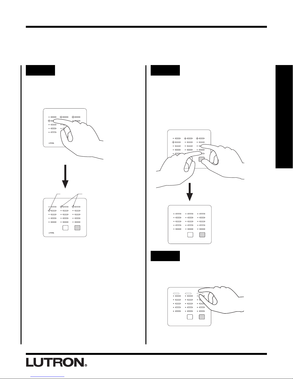
Step 1 Begin ROOM/SCENE
assignment
Simultaneously press and hold the 3rd, 5th,
and ALL OFF buttons in the right most column
until an LED in each column of the Master
Control which you are programming begins to
flash (approximately 3 seconds).
Note: On a 5 button Raise/Lower Wall Master,
press and hold the 3rd, 5th, and Lower
buttons.
Tabletop Master Wall Master
OR
All button columns are factory set as ROOM
buttons.
Changing a column assignment from ROOM to
SCENE (or vice versa) will delete all previous
programming in that column of buttons.
Column of
Buttons
ROOMS SCENES
If the first LED in a
column is flashing, the
buttons in that column
are set as ROOM
buttons.
If the second LED in a
column is flashing, the
buttons in that column
are set as SCENE
buttons.
1-7
RadioRA® Setup Guide
Programming Preparations
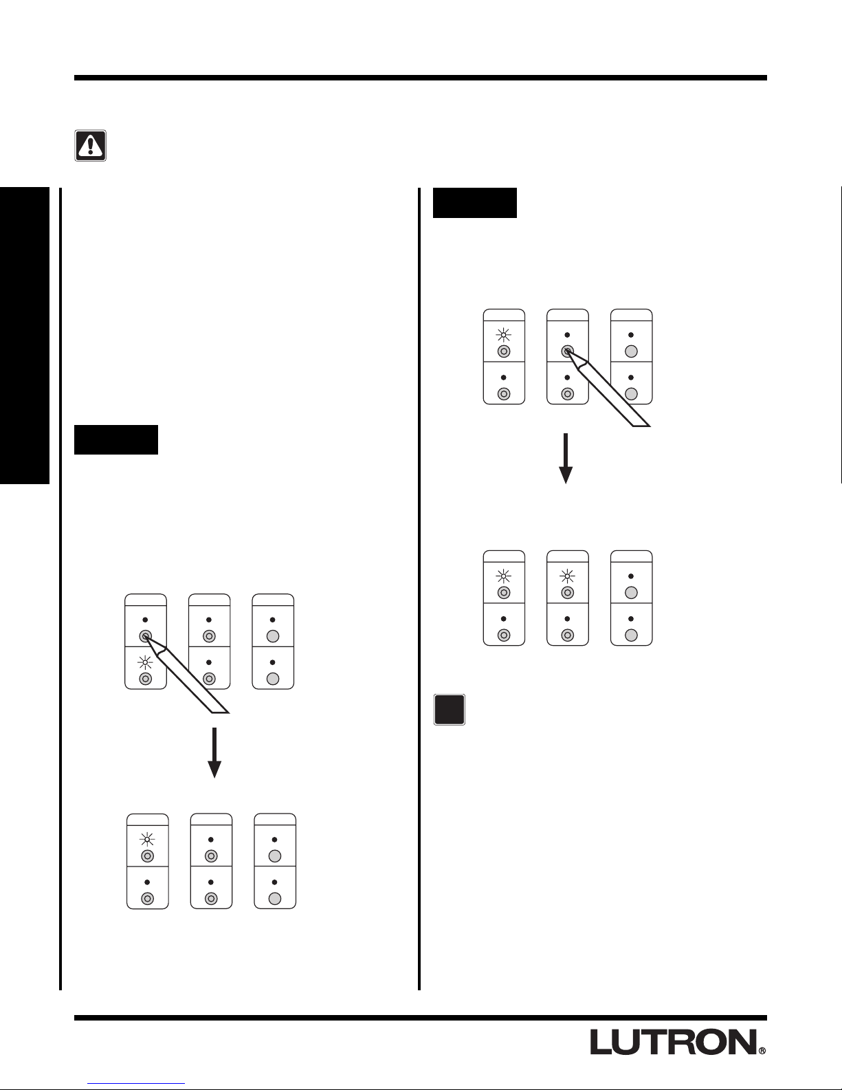
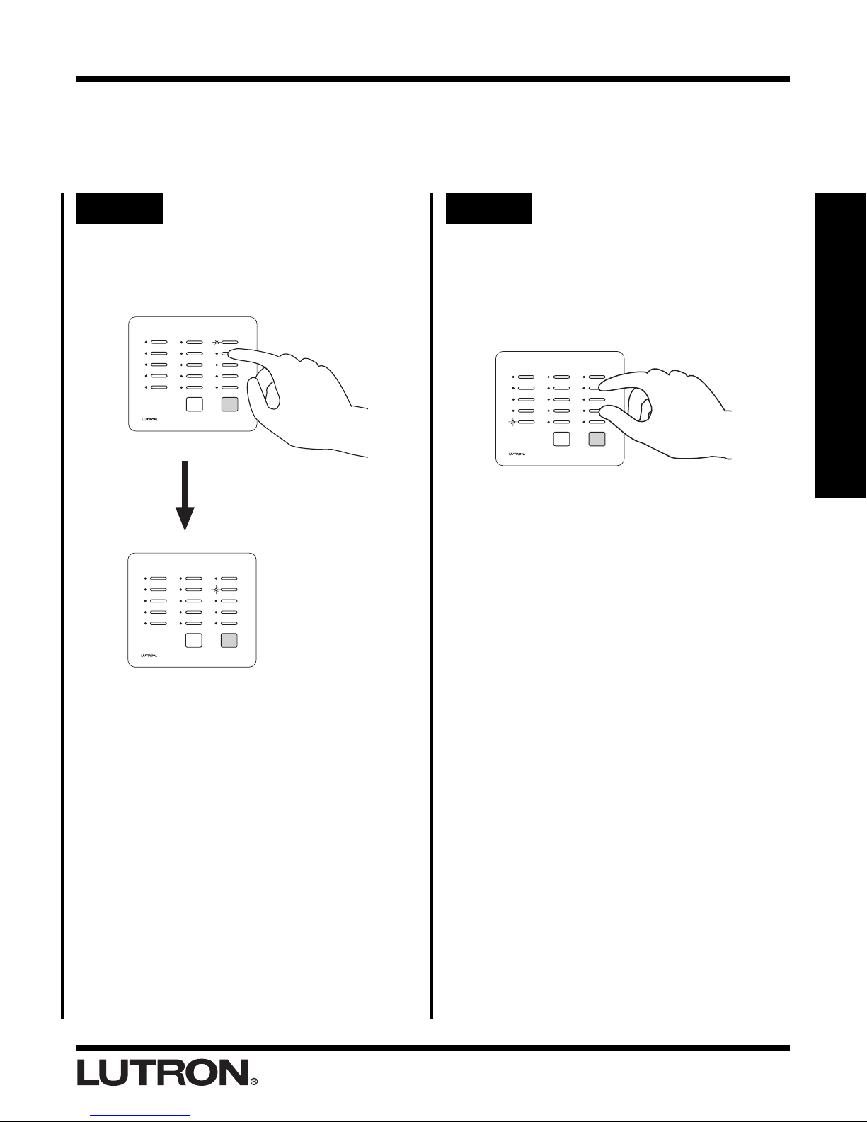
Step 2 Changing ROOM/SCENE
assignments
Press the 1st button in a column to make that
column a ROOM column, or press the 2nd
button to make it a SCENE column.
Shown: Setting
left most column
as SCENES.
ALL OFF
ALL ON
ROOMSSCENES
Step 3 Complete ROOM/SCENE
assignment
Simultaneously press and hold the 3rd, 5th,
and ALL OFF buttons in the right most column
until the LEDs stop flashing (approximately 3
seconds).
Note: On a 5 button Raise/Lower Wall Master,
press and hold the 3rd, 5th, and Lower
buttons.
Section 1 - Start-Up
Step 4 Label columns
Apply the supplied ROOMS or SCENES labels
to the space provided over each button
column.
SCENES ROOMS ROOMS
• Proceed to Assigning Dimmers,
Switches or GRAFIK Eye® Control Units
to ROOM Buttons on page 1-9.
RadioRA® Setup Guide
1-8

ROOM Button Programming
TRON
ALL ON
ALL OFF
Assigning Dimmers, Switches or GRAFIK Eye® Control
Units to ROOM Buttons
NOTE: A column of buttons can also be assigned as SCENES (see page 1-7).
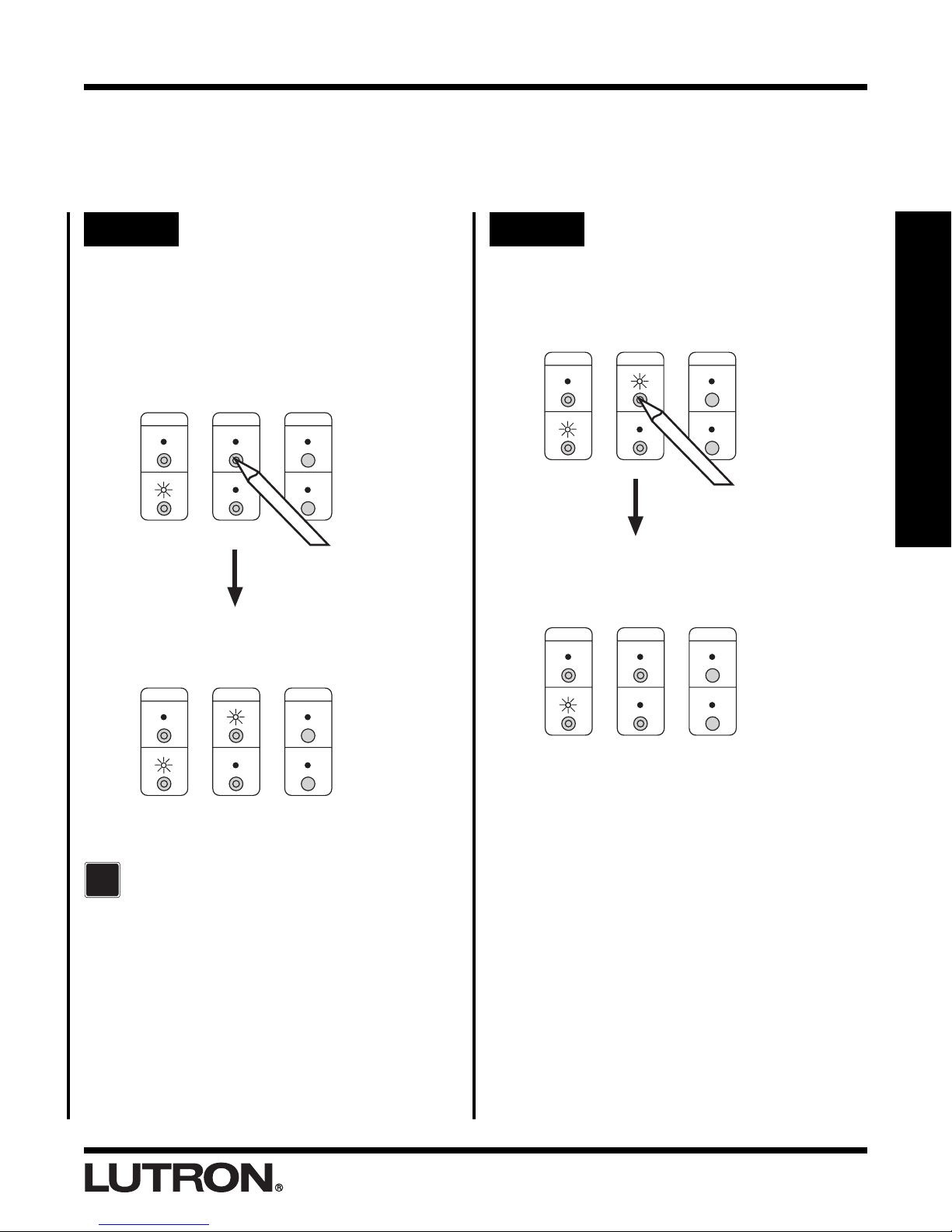
Step 1 Begin assigning Dimmers,
Switches, or GRAFIK Eye®
Control Units to ROOM
buttons
Simultaneously press and hold the 2nd and
4th buttons in the right most column until the
upper right LED begins to flash (approximately
3 seconds).
Tabletop Master Wall Master
OR
Section 1 - Start-Up
Upper right LED flashes.
Step 3 Assign a Dimmer, Switch or
GRAFIK Eye® Control Unit
Control to the button
Notes:
• Multiple Dimmers, Switches or GRAFIK Eye® Control
Units can be assigned to a single ROOM button.
• Controls must be assigned to a Master Control
button while its LED is flashing.
Assign Dimmers or Switches to the Master
Control button by turning the Controls ON.
Assign a GRAFIK Eye® Control Unit to the
Master Control button by changing the
selected GRAFIK Eye® scene.
Dimmer
OR
Switch
GRAFIK Eye®
Control Unit
Step 2 Select a ROOM Button
Press and release the ROOM button that you
want to program. It's LED will begin to flash.
1-9
RadioRA® Setup Guide
Note: GRAFIK Eye® Control Units will automatically
turn on to scene 1 once assigned.
If you assign the wrong Dimmer,
Switch or GRAFIK Eye® Control Unit
to a Master Control button, turn the
Dimmer, Switch or GRAFIK Eye®
Control Unit OFF to unassign it.
ROOM Button Programming
Step 4 Select next ROOM button
To assign Dimmers, Switches or GRAFIK
Eye® Control Units to another Master Control
ROOM button, press and release that button.
Its LED will begin to flash.
Step 5 Complete assigning Dimmers,
Switches, and GRAFIK Eye®
Control Units
Simultaneously press and hold the 2nd and
4th buttons in the right most column until all
LEDs begin to flutter (approximately 3
seconds).
Section 1 - Start-Up
Perform Step 3 for this newly selected ROOM
button.
• Proceed to Step 5 when all ROOM
buttons on this Master Control have
been programmed.
• Repeat Steps 1 through 5 to assign
Dimmers, Switches or GRAFIK Eye®
Control Units to ROOM buttons on any
additional Master Controls.
• Pressing a newly programmed ROOM
button at this point will turn assigned:
Dimmers on to 100% light, Switches ON,
and GRAFIK Eye® Control Units ON to
scene 1.
• Proceed to Setting Light Levels/GRAFIK
Eye® Scene Selection for ROOM Buttons
on page 1-11.
RadioRA® Setup Guide
1-10

ROOM Button Programming
Setting Light Levels/GRAFIK Eye® Scene Selection for
ROOM Buttons
Note: Dimmers can be set to a variable light level. Switches must remain ON. GRAFIK Eye® Control Units can be
set to any scene.
Step 1 Begin setting light levels/
selecting GRAFIK Eye® scenes
Simultaneously press and hold the 1st and 5th
buttons in the right most column until the
upper right LED begins to blink (approximately
3 seconds).
Tabletop Master Wall Master
OR
Section 1 - Start-Up
Step 3 Set light levels for Dimmers
Use the dimming rocker to adjust the light
level of any Dimmer(s) assigned to that button.
This is the light level that the Dimmers will turn
ON to when the ROOM button is pressed ON.
ALL ON
ALL OFF
While setting light levels
• Dimmers assigned to a Master Control
ROOM button cannot be turned OFF.
• Dimmers not assigned to a Master Control
ROOM button cannot be turned ON.
Upper right LED blinks.
Step 2 Select a ROOM Button
Press and release the ROOM button that you
want to program. It's LEDs will begin to blink.
Dimmers, Switches, and GRAFIK Eye® Control Units
that have been assigned to that button will turn ON.
Devices not assigned to that button will turn OFF.
Step 4 Select a GRAFIK Eye® scene
At the GRAFIK Eye® Control Unit, select one
of the pre-programmed scenes (1 through 4)
by turning that scene ON.
LUTRON
The GRAFIK Eye® Control Unit will turn ON to
the scene selected in this step when the ROOM
button is pressed ON. The last scene selected
on the GRAFIK Eye® Control Unit will be the
scene programmed to the ROOM button.
1-11
RadioRA® Setup Guide
ROOM Button Programming
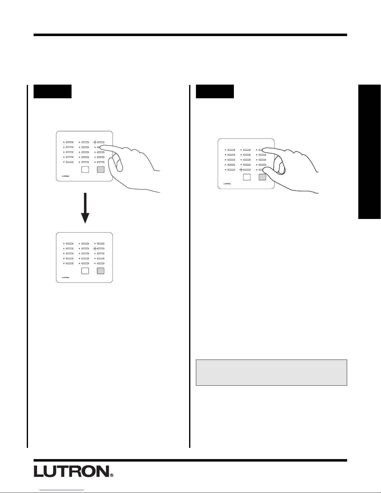
Step 5 Select the next ROOM button
To set the Dimmer light level/select a GRAFIK
Eye® scene for another ROOM button, press
that button. Its LED will begin to blink.
Step 6 Complete setting light levels/
selecting GRAFIK Eye® scenes
Simultaneously press and hold the 1st and 5th
buttons in the right most column until all LEDs
begin to flutter (approximately 3 seconds).
Section 1 - Start-Up
Perform Steps 3 and 4 (whichever apply) for
this newly selected ROOM button.
• Proceed to Step 6 when all ROOM
buttons on this Master Control have
been programmed.
• Repeat Steps 1 through 6 to set the light
levels/select GRAFIK Eye® scenes on
any remaining Master Controls.
• To copy the button programming from
one Master Control to another Master
Control, see Copy Button Programming
on page 2-5 of the Advance Features
Section of this guide.
Congratulations.
Your system is now
programmed. Relax and enjoy your system.
RadioRA® Setup Guide
1-12
SCENE Button Programming
ALL ON
ALL OFF
Assigning Dimmers, Switches or GRAFIK Eye® Control
Units to SCENE Buttons
Note: A column of buttons can also be assigned as ROOMS (see page 1-7).
Step 1 Begin assigning Dimmers,
Switches or GRAFIK Eye®
Control Units to SCENE
buttons
Simultaneously press and hold the 2nd and
4th buttons in the right most column until the
upper right LED begins to flash (approximately
3 seconds).
Tabletop Master Wall Master
OR
Section 1 - Start-Up
Step 3 Assign Dimmers, Switches or
GRAFIK Eye® Control Units to
the button
Note: Multiple Dimmers, Switches or GRAFIK Eye®
Control Units can be assigned to a single SCENE
button.
In this Step you must not only assign light
controls which you want to turn ON when
the button is pressed, you must also assign
light controls which you want to turn OFF
when the button is pressed.
Assign a Dimmer or Switch to the selected
SCENE button by turning the Dimmer or
Switch ON.
Dimmer
OR
Switch
Upper right LED flashes.
Step 2 Select a SCENE button
Press and release the SCENE button that you want to
program. Its LED will begin to flash.
1-13
RadioRA® Setup Guide
Assign a GRAFIK Eye® Control Unit to the
selected SCENE button by changing the
scene of the GRAFIK Eye® Control Unit.
LUTRON
Note: GRAFIK Eye® Control Units will automatically
turn ON to scene 1 once assigned.
If you assign the wrong Dimmer,
Switch or GRAFIK Eye® Control Unit to
a Master Control button, turn the
Dimmer, Switch or GRAFIK Eye®
Control Unit OFF to unassign it.

SCENE Button Programming
Step 4 Select next SCENE button Step 5 Complete assigning Dimmers,
To assign Dimmers, Switches or GRAFIK
Eye® Control Units to another Master Control
SCENE button, press and release that button.
Its LED will begin to flash.
ALL ON ALL OFF
ALL OFF
ALL ON
Simultaneously press and hold the 2nd and 4th
buttons in the right most column until all the
LEDs begin to flutter (approximately 3
seconds).
Switches, and GRAFIK Eye®
Control Units
Section 1 - Start-Up
Perform Step 3 for this newly selected SCENE
button.
• Proceed to Step 5 when all SCENE
buttons on this Master Control have
been programmed.
• Repeat Steps 1 through 5 to assign
Dimmers, Switches or GRAFIK Eye®
Control Units to SCENE buttons on any
additional Master Controls.
• Pressing a newly programmed SCENE
button at this point will turn assigned:
Dimmers on to 50% light, Switches ON,
and GRAFIK Eye® Control Units ON to
scene 1.
• Proceed to Setting Light Levels/GRAFIK
Eye® Scene Selection for SCENE Buttons
on page 1-15.
RadioRA® Setup Guide
1-14

SCENE Button Programming
Setting Light Levels/GRAFIK Eye® Scene Selection for
SCENE Buttons
Note: Dimmers can be set to a variable light level or turned OFF. Switches can be turned ON or OFF. GRAFIK
Eye® Control Units can be set to any scene or turned OFF.
Step 1 Begin setting light levels/
GRAFIK Eye® scene selection
Simultaneously press the 1st and 5th buttons
in the right most column until the upper right
LED begins to blink (approximately 3
seconds).
Tabletop Master Wall Master
OR
Section 1 - Start-Up
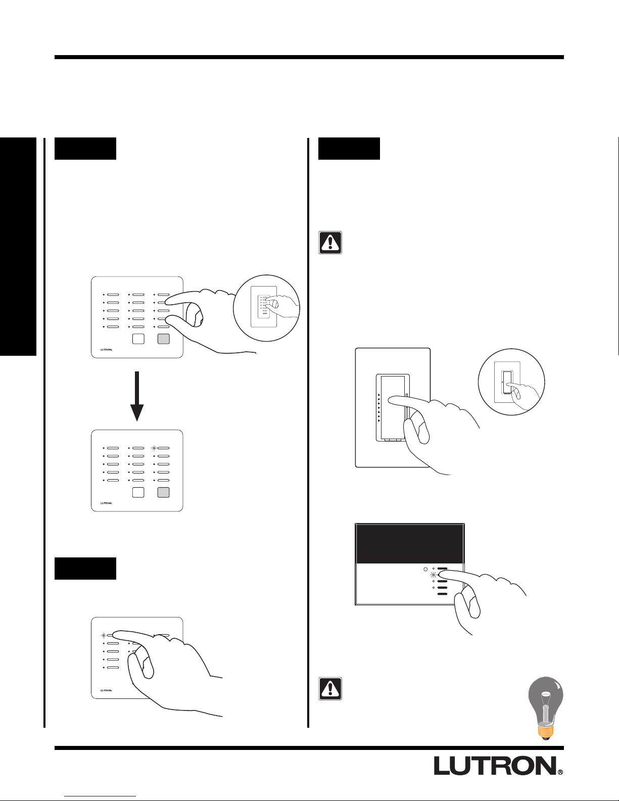
Step 3 Set light levels/select GRAFIK
Eye® scenes
Go to any assigned Dimmer (which will be
ON at 50%). Adjust this Dimmers programmed
light level for the selected SCENE button
using the dimming rocker, or turn the Dimmer
OFF if it is to be turned OFF when this SCENE
button is pressed.
ALL ON
ALL OFF
Adjust light levels
Go to any assigned Switch (which will be
ON). Turn the Switch OFF if it is to be turned
OFF when this SCENE button is pressed.
OR
Turn OFF
Upper right LED blinks.
Step 2 Select a SCENE button
Press and release the SCENE button that you want to
program. Its LED will begin to blink.
All devices assigned to that button will turn ON
to: Dimmers 50% light level, Switches ON, and
GRAFIK Eye® Control Units to scene 1. All
devices not assigned to that button will turn
OFF.
Go to any assigned GRAFIK Eye® Control
Unit (which will be ON at scene 1). Select from
pre-programmed scenes (1 through 4) by
turning that scene ON or select OFF if it is to
be turned OFF when this SCENE button is
pressed.
LUTRON
RadioRA® Setup Guide1-15

SCENE Button Programming
Step 4 Select next SCENE button
To set the light level for another Master
Control SCENE button, press and release that
button. Its LEDs will begin to blink.
ALL ON ALL OFF
ALL OFF
ALL ON
Perform Step 3 for this newly selected SCENE
button.
Step 5 Complete setting light levels/
selecting GRAFIK Eye® scenes
Simultaneously press the 1st and 5th buttons
in the right most column until all LEDs begin to
flutter (approximately 3 seconds).
Section 1 - Start-Up
If at any point in this procedure you are unsure
which Dimmers, Switches or GRAFIK Eye®
Control Units are assigned to a Master Control
SCENE button
• Press the button next to the blinking LED.
• The LED will begin to flash (slower) and all
Dimmers, Switches, and GRAFIK Eye®
Control Units assigned to that Master
Control SCENE button will turn ON to full
intensity.
Note: Dimmer, Switch or GRAFIK Eye®
Control Unit assignments cannot be
changed at this time. See page 1-13 to
change control assignment.
• Press the same Master Control SCENE
button again to continue setting light levels.
The LED will begin to blink again (faster).
• Proceed to Step 5 when all SCENE
buttons on this Master Control have
been programmed.
• Repeat Steps 1 through 5 to set the light
levels/select GRAFIK Eye® scenes on
any remaining Master Controls.
• To copy the button programming from
one Master Control to another Master
Control, see Copy Button Programming
on page 2-5.
You may now operate your Master Control
SCENE buttons
RadioRA® Setup Guide 1-16

Advanced Programming
ALL ON
ALL OFF
Programming the ALL ON Button
The ALL ON button on a RadioRA® Master Control will, by default, turn ON all Dimmers and Switches to full
intensity, and GRAFIK Eye
turn ON selected Dimmers (to full intensity), Switches, or GRAFIK Eye Control Units (to Scene 1).
® Control Units to Scene 1 when pressed. The ALL ON button can be programmed to
These programming steps only apply to Master
Controls equipped with an ALL ON button.
Step 1 Begin the ALL ON button
programming
On the Master Control you want to program,
simultaneously press and hold the 2nd and 4th
buttons in the right most column until the
upper right LED begins to flash (approximately
3 seconds).
Tabletop Master Wall Master
OR
Step 2 Press the ALL ON button
Press the ALL ON button on the Master
Control you are programming.
The LEDs in all columns will simultaneously
cycle from bottom to top.
Section 2 - Advanced Features
Upper right LED flashes.
LEDs cycle UP
All Dimming/Switching Controls and GRAFIK
Eye® Control Units will turn ON.
RadioRA® Setup Guide2-1

Advanced Programming
TRON
Step 3 Remove a Dimmer, Switch, or
GRAFIK Eye® Control Unit
from the ALL ON button
Turn OFF the Dimmer(s), Switch(es), or
GRAFIK Eye® Control Unit(s) that you want
removed from the ALL ON button
programming.
Dimmer
OR
Switch
GRAFIK Eye®
Control Unit
Step 4 Complete the ALL ON button
programming
Simultaneously press and hold the 2nd and
4th buttons in the right most column until all
LEDs begin to flutter (approximately 3
seconds).
• Repeat Steps 1 through 4 to re-program
the ALL ON button any additional Master
Controls.
If you remove the wrong
Dimmer, Switch, or GRAFIK
Eye® Control Unit from the
ALL ON button, turn the
Dimmer, Switch, or GRAFIK
Eye® Control Unit ON to
reassign it.
Section 2 - Advanced Features
RadioRA® Setup Guide 2-2

Advanced Programming
ALL ON
ALL OFF
Programming the ALL OFF Button
The ALL OFF button on a RadioRA® Master Control will, by default, turn OFF all Dimmers, Switches, and GRAFIK
Eye
® Control Units when pressed. The ALL OFF button can be programmed to turn selected Dimmers, Switches,
or GRAFIK Eye® Control Units OFF.
These programming steps only apply to Master
Controls equipped with an ALL OFF button.
Step 1 Begin the ALL OFF button
programming
On the Master Control you want to program,
simultaneously press and hold the 2nd and 4th
buttons in the right most column until the
upper right LED begins to flash (approximately
3 seconds).
Tabletop Master Wall Master
OR
Step 2 Press the ALL OFF button
Press the ALL OFF button on the Master
Control you are programming.
The LEDs in all columns will simultaneously
cycle from top to bottom.
Section 2 - Advanced Features
Upper right LED flashes.
LEDs cycle DOWN
All Dimming/Switching Controls and GRAFIK
Eye® Control Units will turn ON.
RadioRA® Setup Guide2-3

Advanced Programming
TRON
Step 3 Remove a Dimmer, Switch, or
GRAFIK Eye® Control Unit
from the ALL OFF button
Turn OFF the Dimmer(s), Switch(es), or
GRAFIK Eye® Control Unit(s) that you want
removed from the ALL OFF button.
Dimmer
OR
Switch
GRAFIK Eye®
Control Unit
Step 4 Complete the ALL OFF button
programming
Simultaneously press and hold the 2nd and
4th buttons in the right most column until all
the LEDs begin to flutter (approximately 3
seconds).
If you remove the wrong
Dimmer, Switch, or GRAFIK
Eye® Control Unit from the
ALL OFF button, turn the
Dimmer, Switch, or GRAFIK
Eye® Control Unit ON to
reassign it.
• Repeat Steps 1 through 4 to re-program
the ALL OFF button any additional
Master Controls.
Section 2 - Advanced Features
RadioRA® Setup Guide 2-4

Advanced Programming
Copying Button Programming
If you have more than one Master Control in your system, you can copy the button programming from a
previously programmed Master Control button to an un-programmed Master Control button so that both buttons
function identically.
Step 1 Begin Copying Button
Programming
On the Master Control you want to program,
simultaneously press and hold the 1st and 5th
buttons in the right most column until the
upper right LED begins to blink (approximately
3 seconds).
Tabletop Master Wall Master
Un-programmed
Master Control
OR
Step 2 Select the button you want to
program
Press and release the button you want to
program. Its LED will begin to blink.
ALL ON
ALL OFF
Un-programmed
Master Control
LED blinks.
Section 2 - Advanced Features
Un-programmed
Master Control
Note: LEDs on all other Master Controls will
flash.
Upper right LED blinks.
Un-programmed
Master Control
The programming from a ROOM button cannot
be copied to a SCENE button, or vice versa.
RadioRA® Setup Guide2-5

Advanced Programming
Step 3 Select the button you want to
copy
On a previously programmed Master Control,
press the programmed button that you want to
copy until its LED turns OFF (approximately 3
seconds).
Previously Programmed
Master Control
When the LED turns OFF
for a few seconds and
then resumes flashing
programming has been
copied to
Step 4 Complete Copy Button
Programming
Simultaneously press and hold the 1st and 5th
buttons in the right most column until all LEDs
begin to flutter (approximately 3 seconds).
Newly Programmed
Master Control
Section 2 - Advanced Features
Previously Programmed
Master Control
Newly Programmed
• Repeat Steps 2 and 3 for all Master
Control buttons that you want to copy
programming to.
• Repeat Steps 1 through 4 to copy button
programming on any remaining
unprogrammed Master Controls.
Master Control
RadioRA® Setup Guide 2-6

Advanced Programming
Erasing Button Programming
Erasing Button Programming will remove all Dimming or Switching Controls assigned to a Master Control button
and erase that button's programming.
Step 1 Begin Erasing Button
Programming
Simultaneously press the 2nd and 4th buttons
in the right most column until the upper right
LED begins to flash (approximately 3
seconds).
Step 2 Select button to erase
Press and hold the button you wish to erase
until its LED begins to flutter (approximately 3
seconds).
Note: The LED will
first flash (slower)
and then begin to
flutter (faster).
ALL ON ALL OFF
ALL OFF
ALL ON
Section 2 - Advanced Features
Upper right LED flashes.
LED will flutter for only 3 seconds.
RadioRA® Setup Guide2-7

Advanced Programming
Step 3 Erase button
While the LED is fluttering, press the ALL OFF
or Lower button in the right most column.
The LED will stop fluttering and begin to flash.
All Dimmers and/or Switches will turn OFF,
and programming is now erased from that
Master Control button.
OR
Step 4 Complete Erasing Button
Programming
Simultaneously press the 2nd and 4th buttons
Wall MasterTabletop Master
in the right most column until all LEDs begin to
flutter (approximately 3 seconds).
• Repeat Steps 2 and 3 for all Master
Control buttons with programming that
you want to erase.
Section 2 - Advanced Features
RadioRA® Setup Guide 2-8

Adding Basic System Components
?
Adding an Auxiliary Repeater
Auxiliary Repeaters (up to a maximum of 3) can be added to a system to increase range and improve reliability.
Ensure all system devices are powered up and operating prior to adding any Auxiliary Repeaters.
Step 1 Begin Auxiliary Repeater
Activation
Press and hold the ACTIVATE REPEATER
button on any previously activated Repeater
until the green ACTIVATE REPEATER LED
turns ON (approximately 3 seconds).
REPEATER
MAIN
AUXILIARY
Green Activate Repeater LED will turn ON on
all existing system Repeaters.
REPEATER
MAIN
ACTIVATE
REPEATER
CONTROLS
ACTIVATE
REPEATER
VERIFY
BEEP
FLASH
VERIFY
BEEP
Step 2 Activate Auxiliary Repeater
Press and hold the ACTIVATE REPEATER
button on the new Auxiliary Repeater until the
green ACTIVATE REPEATER LED begins to
flash (approximately 3 seconds).
REPEATER
MAIN
AUXILIARY
Green LED will stay ON when Repeater has
been activated.
REPEATER
MAIN
ACTIVATE
REPEATER
CONTROLS
ACTIVATE
REPEATER
VERIFY
BEEP
FLASH
VERIFY
BEEP
AUXILIARY
If the ACTIVATE REPEATER LED turns
?
orange, consult the Troubleshooting Guide,
Sections
Section 3 - Expanding Your System
CONTROLS
FLASH
AUXILIARY
CONTROLS
FLASH
If the ACTIVATE REPEATER LED turns
orange, consult the Troubleshooting Guide,
I.
Section
I, II or III.
RadioRA® Setup Guide3-1

Adding Basic System Components
Step 3 Complete Repeater activation
Press and hold the ACTIVATE REPEATER
button on any Repeater until the green
ACTIVATE REPEATER LED turns OFF
(approximately 3 seconds).
REPEATER
MAIN
ACTIVATE
REPEATER
VERIFY
BEEP
AUXILIARY
CONTROLS
FLASH
The green ACTIVATE REPEATER LED on
ALL
Repeaters will turn OFF. The MAIN or
AUXILIARY green LED will remain ON.
REPEATER
MAIN
AUXILIARY
ACTIVATE
REPEATER
CONTROLS
VERIFY
BEEP
FLASH
• Repeaters are now activated.
Section 3 - Expanding Your System
RadioRA® Setup Guide 3-2

Adding Basic System Components
?
Adding Controls
Master Controls may be added to your system up to a maximum of 12. Dimmers, Switches, and GRAFIK Eye®
Control Units may be added up to a maximum of 32.
Step 1 Begin control activation
Press and hold the ACTIVATE CONTROLS
button on
ACTIVATE CONTROLS LED turns ON
(approximately 3 seconds).
REPEATER
MAIN
AUXILIARY
The green ACTIVATE CONTROLS LED on
ALL
REPEATER
MAIN
any
Repeater until the green
ACTIVATE
REPEATER
CONTROLS
VERIFY
BEEP
FLASH
Repeaters will turn ON.
ACTIVATE
REPEATER
VERIFY
BEEP
Step 2 Activate Controls
To add a Master Control
Go to the new Master Control.
Note: All LEDs will be OFF prior to activation.
Press any button.
• All LEDs will flutter, then
• Top and bottom row will flash alternately
Tabletop Master
OR
Wall Master
ALL ON
ALL OFF
AUXILIARY
If the Activate Controls LED fails to turn ON,
?
consult the Troubleshooting Guide, Section
Section 3 - Expanding Your System
CONTROLS
FLASH
IV.
Middle row of LEDs will turn ON when the
Master Control has been activated.
If a Master Control fails to respond as
described above, consult the Troubleshooting
Guide, Section
VI or VII.
Repeat the above Step to activate any
remaining Master Controls
Activate one Master Control at a time. Wait for
the middle row of LEDs to turn ON before
activating any remaining Master Controls.
RadioRA® Setup Guide3-3

Adding Basic System Components
TRON
Step 3 Complete control activation
To add a Dimmer, Switch or GRAFIK Eye®
Control Unit
Go to the new Dimmer, Switch or GRAFIK Eye®
Control Unit.
Turn the Dimmer or Switch ON or OFF by
pressing the tapswitch. Change the selected
scene on the GRAFIK Eye® Control Unit by
pressing any of the preset buttons.
Dimmer Switch
OR
GRAFIK Eye®
Control Unit
Press and hold the ACTIVATE CONTROLS
button on any Repeater until the green
ACTIVATE CONTROLS LED turns OFF
(approximately 3 seconds).
REPEATER
MAIN
AUXILIARY
ACTIVATE
REPEATER
CONTROLS
VERIFY
BEEP
FLASH
The green ACTIVATE CONTROLS LED on
ALL
Repeaters will turn OFF. The MAIN or
AUXILIARY green LED will remain on.
REPEATER
MAIN
ACTIVATE
REPEATER
VERIFY
BEEP
The lights that the Dimmer, Switch or GRAFIK
Eye® Control Unit controls will turn ON and
OFF a few times when it has been activated.
If a Dimmer, Switch or GRAFIK Eye® Control
Unit fails to respond as described above,
?
consult the Troubleshooting Guide, Sections
Repeat the above Step to activate any
remaining Dimmers, Switches or GRAFIK
Eye® Control Units
Activate one Dimmer, Switch or GRAFIK Eye
Control Unit at a time. Wait for the Dimmer,
Switch or GRAFIK Eye® Control Unit to flash its
light(s) before activating any remaining
Dimmers, Switches or GRAFIK Eye® Control
Units.
AUXILIARY
CONTROLS
FLASH
• Controls are now activated.
• If you want to Verify that all new
Controls have been activated, see Flash
Mode in the Troubleshooting Section on
V.
page 4-4.
• For programming instructions, see
Assigning a Column of buttons as
ROOMS or SCENES on page 1-7.
RadioRA® Setup Guide 3-4
Section 3 - Expanding Your System

Adding a Switch Closure Interface
?
Guide f
Guide for o erating instructions
Activating a Switch Closure Interface
The Switch Closure Interface is a special type of Master Control. Therefore, the System can have a maximum of
12 Master Controls plus a Switch Closure Interface. For every 1 Master Control NOT used, 1 Switch Closure
Interface may be used in its place.
The Switch Closure Interface has a 15 second
delay after applying power. During this time the
Power LED will blink. When the Power LED
stays ON, the unit is ready for operation.
Step 1 Begin Switch Closure
Interface activation
Press and hold the ACTIVATE CONTROLS
button on
ACTIVATE CONTROLS LED turns ON
(approximately 3 seconds).
REPEATER
MAIN
AUXILIARY
The green ACTIVATE CONTROLS LED on
ALL
REPEATER
MAIN
any
Repeater until the green
ACTIVATE
REPEATER
CONTROLS
VERIFY
BEEP
FLASH
Repeaters will turn ON.
ACTIVATE
REPEATER
VERIFY
BEEP
Step 2 Activate Switch Closure
Interface
Press any button.
or operating instructions.
For additional assistance call the
Hotline:
1-800-523-9466
FCC ID JPZ0005
This device complies with part 15 of the FCC Rules. Operation is subject to the following two
conditions: (1) This device may not cause harmful interference and (2) This device must accept any
interference received including interference that may cause undesired operation.
18V
AC IN
• All input LEDs will flutter, then
• The Flash LED and Input 1 LED will
alternately flash.
For additional assistance call the
1-800-523-9466
Hotline:
FCC ID JPZ0005
This device complies with part 15 of the FCC Rules. Operation is subject to the following two
conditions: (1) This device may not cause harmful interference and (2) This device must accept any
interference received including interference that may cause undesired operation.
Patents Pending
.
Patents Pending
Lutron Technical Assistance
Full
Input 1
Input 2
Input 3
Input 4
Input 5
Lutron Technical Assistance
Flash
Common
AUXILIARY
CONTROLS
FLASH
Section 3 - Expanding Your System
RadioRA® Setup Guide3-5
Full
AC IN
18V
Input 1
Input 2
Input 3
Input 4
Input 5
Flash
Common
Input 4 LED will remain ON when the Switch
Closure Interface has been activated.
If a Switch Closure Interface fails to respond as
described above, consult the Troubleshooting
Guide, Section
XI.

Adding a Switch Closure Interface
Step 3 Complete Switch Closure
Interface activation
Press and hold the ACTIVATE CONTROLS
button on any Repeater until the green
ACTIVATE CONTROLS LED turns OFF
(approximately 3 seconds).
REPEATER
MAIN
ACTIVATE
REPEATER
VERIFY
BEEP
AUXILIARY
CONTROLS
FLASH
The green ACTIVATE CONTROLS LED on
ALL
Repeaters will turn OFF. The MAIN or
AUXILIARY LED will remain on.
REPEATER
MAIN
AUXILIARY
ACTIVATE
REPEATER
CONTROLS
VERIFY
BEEP
FLASH
• The Switch Closure Input Interface is
now activated.
• If you want to Verify that your Switch
Closure Interface has been activated,
see Flash Mode in the Troubleshooting
Section on page 4-4.
• Proceed to Assigning a Dimmers,
Switches or GRAFIK Eye® Control Units
to Input Channels on page 3-7.
Section 3 - Expanding Your System
RadioRA® Setup Guide 3-6

Adding a Switch Closure Interface
In ut 5
Assigning Dimmers, Switches or GRAFIK Eye® Control
Units to Input Channels
Programming the Switch Closure Interface to control a light or a group of lights by a specified Input Channel.
Step 1 Begin assigning Dimmers,
Switches or GRAFIK Eye®
Control Units to Input
Channels
Simultaneously press and hold the Program
and Input Select buttons until the Program
LED begins to flash (approximately 3
seconds).
See the Switch Closure Interface Addendum to the Programming
Guide for operating instructions.
For additional assistance call the
Hotline:
1-800-523-9466
FCC ID JPZ0005
This device complies with part 15 of the FCC Rules. Operation is subject to the following two
conditions: (1) This device may not cause harmful interference and (2) This device must accept any
interference received including interference that may cause undesired operation.
18V
AC IN
Patents Pending
Lutron Technical Assistance
Full
Input 2
Input 3
Input 4
Input 5
Flash
Input 1
Common
Step 2 Select an Input Channel to
program
Press and release the Input Select button until
the LED for the desired input channel turns
ON.
See the Switch Closure Interface Addendum to the Programming
Guide for operating instructions.
For additional assistance call the
1-800-523-9466
Hotline:
FCC ID JPZ0005
This device complies with part 15 of the FCC Rules. Operation is subject to the following two
conditions: (1) This device may not cause harmful interference and (2) This device must accept any
interference received including interference that may cause undesired operation.
18V
AC IN
Patents Pending
Lutron Technical Assistance
Full
Input 1
Input 2
Input 3
Input 4
Input 5
Flash
Common
Program LED flashes. Input 1 LED and a
Closure Type LED will turn ON.
Section 3 - Expanding Your System
See the Switch Closure Interface Addendum to the Programming
Guide for operating instructions.
For additional assistance call the
Hotline:
FCC ID JPZ0005
This device complies with part 15 of the FCC Rules. Operation is subject to the following two
conditions: (1) This device may not cause harmful interference and (2) This device must accept any
interference received including interference that may cause undesired operation.
18V
AC IN
1-800-523-9466
Patents Pending
Lutron Technical Assistance
Full
Input 1
Input 2
Input 3
Input 4
Input 5
Flash
Common
Program LED
Selected Switch Closure Input Channel will
have its LED ON.
See the Switch Closure Interface Addendum to the Programming
Guide for operating instructions.
For additional assistance call the
Hotline:
1-800-523-9466
FCC ID JPZ0005
This device complies with part 15 of the FCC Rules. Operation is subject to the following two
conditions: (1) This device may not cause harmful interference and (2) This device must accept any
interference received including interference that may cause undesired operation.
18V
AC IN
Patents Pending
Lutron Technical Assistance
Full
Input 1
Input 2
Input 3
Input 4
Input 5
Flash
Common
RadioRA® Setup Guide3-7

Adding a Switch Closure Interface
FCC ID JPZ0005
Patents Pending
Step 3 Assign Dimmers, Switches or
GRAFIK Eye® Control Units to
Input Channel
In this Step you must not only assign light
controls which you want to turn ON when
the Input Channel is selected, you must also
assign light controls which you want to turn
OFF when the input channel is selected.
Assign a Dimmer or Switch to the selected
Input Channel by turning the Dimmer or
Switch ON.
Dimmer
OR
Switch
Step 4 Select Input Channel switch
closure type
To assign an input channel switch closure
type, press the Closure Type button to toggle
between a Momentary and a Maintained input.
Note: Momentary inputs must be closed for a
minimum of 100 msec.
This device complies with part 15 of the FCC Rules. Operation is subject to the following two
conditions: (1) This device may not cause harmful interference and (2) This device must accept any
interference received including interference that may cause undesired operation.
Full
Input 2
Input 3
Input 4
Input 5
Flash
Common
AC IN
18V
Input 1
Maintained
Momentary
• Inputs 1 through 5 can be independently
selected as Maintained or Momentary.
• Full and Flash are Maintained closures and
cannot be changed.
Maintained Input Example
Assign a GRAFIK Eye® Control Unit to the
selected Input Channel by changing the scene
of the GRAFIK Eye® Control Unit.
LUTRON
Note: GRAFIK Eye® Control Units will automatically
turn ON to scene 1 once assigned.
If you assign the wrong Dimmer,
Switch or GRAFIK Eye® Control Unit to
a Input Channel, turn the Dimmer,
Switch or GRAFIK Eye® Control Unit
OFF to unassign it.
Switch
Open
Activate
Switch
A Maintained switch closure will turn an input
SCENE ON. Input SCENE remains ON until
the switch closure is released. When released,
the input SCENE returns to OFF..
Momentary Input Example
Switch
Open
Activate
Switch
A Momentary switch closure will turn a SCENE
ON. The input SCENE remains ON after the
switch closure has been released, until the
status of a Dimmer or Switch in that SCENE is
changed.
• Continued on next page.
Release
Switch
Release
Switch
Section 3 - Expanding Your System
RadioRA® Setup Guide 3-8

Adding a Switch Closure Interface
In ut 5
In ut 5
Step 5 Select next Input Channel to
program
To assign Dimmers, Switches or GRAFIK
Eye® Control Units to another Switch Closure
Input Channel, press and release the Input
Select button until that channel's LED turns
ON.
See the Switch Closure Interface Addendum to the Programming
Guide for operating instructions.
For additional assistance call the
1-800-523-9466
Hotline:
FCC ID JPZ0005
This device complies with part 15 of the FCC Rules. Operation is subject to the following two
conditions: (1) This device may not cause harmful interference and (2) This device must accept any
interference received including interference that may cause undesired operation.
18V
AC IN
See the Switch Closure Interface Addendum to the Programming
Guide for operating instructions.
For additional assistance call the
Hotline:
1-800-523-9466
FCC ID JPZ0005
This device complies with part 15 of the FCC Rules. Operation is subject to the following two
conditions: (1) This device may not cause harmful interference and (2) This device must accept any
interference received including interference that may cause undesired operation.
Patents Pending
Lutron Technical Assistance
Patents Pending
Lutron Technical Assistance
Full
Input 1
Input 2
Input 3
Input 4
Input 5
Flash
Common
Step 6 Complete assigning Dimmers,
Switches or GRAFIK Eye®
Control Units to Input
Channels
Press and hold the Program and Input Select
buttons until the flashing Program LED turns
OFF (approximately 3 seconds).
See the Switch Closure Interface Addendum to the Programming
Guide for operating instructions.
For additional assistance call the
Hotline:
1-800-523-9466
FCC ID JPZ0005
This device complies with part 15 of the FCC Rules. Operation is subject to the following two
conditions: (1) This device may not cause harmful interference and (2) This device must accept any
interference received including interference that may cause undesired operation.
18V
AC IN
All Input LEDs will flutter for a few seconds
when completing.
Patents Pending
Lutron Technical Assistance
Full
Input 2
Input 3
Input 4
Input 5
Flash
Input 1
Common
Full
18V
AC IN
Input 1
Input 2
Input 3
Input 4
Input 5
Flash
Common
Section 3 - Expanding Your System
Perform Steps 3 and 4 for this newly selected
Input Channel.
• Proceed to Step 6 when all Input
Channels on the Switch Closure
Interface have been programmed.
RadioRA® Setup Guide3-9
• Proceed to Setting Light Levels/GRAFIK
Eye® Scene Selection on page 3-10.

Adding a Switch Closure Interface
See the Switch Closure Interface Addendum to the Programming
In ut 5
Setting Light Levels/GRAFIK Eye® Scene Selection for
Input Channels
Note: Dimmers can have a variable light level set or turned OFF. Switches can be turned ON or OFF. GRAFIK
Eye® Control Units can be set to any scene or turned OFF.
Step 1 Begin setting light levels/
GRAFIK Eye® Scene Selection
Press and hold the Program button until the
Program LED begins to blink (approximately 3
seconds).
Guide for operating instructions.
For additional assistance call the
1-800-523-9466
Hotline:
FCC ID JPZ0005
This device complies with part 15 of the FCC Rules. Operation is subject to the following two
conditions: (1) This device may not cause harmful interference and (2) This device must accept any
interference received including interference that may cause undesired operation.
18V
AC IN
Program LED blinks. Input 1 LED and a
Closure Type LED will turn ON.
See the Switch Closure Interface Addendum to the Programming
Guide for operating instructions.
For additional assistance call the
Hotline:
1-800-523-9466
FCC ID JPZ0005
This device complies with part 15 of the FCC Rules. Operation is subject to the following two
conditions: (1) This device may not cause harmful interference and (2) This device must accept any
interference received including interference that may cause undesired operation.
Patents Pending
Lutron Technical Assistance
Patents Pending
Lutron Technical Assistance
Full
Input 1
Input 2
Input 3
Input 4
Input 5
Flash
Common
Step 2 Select an Input Channel to
program
Press and release the Input Select button until
the LED for the desired input channel turns
ON.
See the Switch Closure Interface Addendum to the Programming
Guide for operating instructions.
For additional assistance call the
1-800-523-9466
Hotline:
FCC ID JPZ0005
This device complies with part 15 of the FCC Rules. Operation is subject to the following two
conditions: (1) This device may not cause harmful interference and (2) This device must accept any
interference received including interference that may cause undesired operation.
18V
AC IN
Selected Switch Closure Input Channel will
have its LED ON.
See the Switch Closure Interface Addendum to the Programming
Guide for operating instructions.
For additional assistance call the
Hotline:
1-800-523-9466
FCC ID JPZ0005
This device complies with part 15 of the FCC Rules. Operation is subject to the following two
conditions: (1) This device may not cause harmful interference and (2) This device must accept any
interference received including interference that may cause undesired operation.
Patents Pending
Lutron Technical Assistance
Patents Pending
Lutron Technical Assistance
Full
Input 1
Input 2
Input 3
Input 4
Input 5
Flash
Common
Full
AC IN
18V
Input 1
Input 2
Input 3
Input 4
Input 5
Flash
Common
Dimmers assigned to Input 1 will turn ON to
50% light level. Switches assigned to Input 1
will turn ON. GRAFIK Eye® Control Units
assigned to Input 1 will turn ON to scene 1.
Dimmers, Switches or GRAFIK Eye® Control
Units not assigned to Input 1 will turn OFF.
Note: Closure Type may not be changed while setting
light levels.
Full
AC IN
18V
Input 1
Input 2
Input 3
Input 4
Input 5
Flash
Common
Note: Light levels cannot be set for FULL and FLASH
dedicated security inputs. The default for these inputs
is, Dimmers and Switches - ON at 100%, GRAFIK
Eye® Control Units - ON to scene 1.
• Continued on next page.
RadioRA® Setup Guide 3-10
Section 3 - Expanding Your System

Adding a Switch Closure Interface
In ut 5
Step 3 Set light levels/select GRAFIK
Eye® scenes
Go to any assigned Dimmer (which will be
ON at 50%). Adjust this Dimmers programmed
light level for the selected SCENE button
using the dimming rocker, or turn the Dimmer
OFF if it is to be turned OFF when this Input
Channel is activated.
OR
Adjust light levels
Go to any assigned Switch (which will be
ON). Turn the Switch OFF if it is to be turned
OFF when this Input Channel is activated.
Turn OFF
Step 4 Select next Input Channel to
program
To set the light level for another Input
Channel, press the Input Select button to turn
that channel's LED ON.
See the Switch Closure Interface Addendum to the Programming
Guide for operating instructions.
For additional assistance call the
1-800-523-9466
Hotline:
FCC ID JPZ0005
This device complies with part 15 of the FCC Rules. Operation is subject to the following two
conditions: (1) This device may not cause harmful interference and (2) This device must accept any
interference received including interference that may cause undesired operation.
18V
AC IN
Patents Pending
Lutron Technical Assistance
Full
Input 1
Input 2
Input 3
Input 4
Input 5
Flash
Common
Section 3 - Expanding Your System
Go to any assigned GRAFIK Eye® Control
Unit (which will be ON at scene 1). Select from
pre-programmed scenes (1 through 4) by
turning that scene ON or select OFF if it is to
be turned OFF when this Input Channel is
activated.
LUTRON
Selected Switch Closure Input Channel will
have its LED ON.
See the Switch Closure Interface Addendum to the Programming
Guide for operating instructions.
For additional assistance call the
1-800-523-9466
Hotline:
FCC ID JPZ0005
This device complies with part 15 of the FCC Rules. Operation is subject to the following two
conditions: (1) This device may not cause harmful interference and (2) This device must accept any
interference received including interference that may cause undesired operation.
18V
AC IN
Patents Pending
Lutron Technical Assistance
Full
Input 2
Input 3
Input 4
Input 5
Flash
Input 1
Common
RadioRA® Setup Guide3-11

Adding a Switch Closure Interface
Step 5 Complete setting light levels/
GRAFIK Eye® Scene Selection
Press the Program button until the blinking
Program LED turns OFF (approximately 3
seconds).
See the Switch Closure Interface Addendum to the Programming
Guide for operating instructions.
For additional assistance call the
1-800-523-9466
Hotline:
FCC ID JPZ0005
This device complies with part 15 of the FCC Rules. Operation is subject to the following two
conditions: (1) This device may not cause harmful interference and (2) This device must accept any
interference received including interference that may cause undesired operation.
18V
AC IN
Patents Pending
Lutron Technical Assistance
Full
Input 2
Input 3
Input 4
Input 5
Flash
Input 1
Common
All Input LEDs will flutter for a few seconds
when completing.
Section 3 - Expanding Your System
RadioRA® Setup Guide 3-12

Troubleshooting Guide
Proper operation of the RadioRA® Wireless Central Home Lighting Control System is based upon a complex series of radio
frequency (RF) communications between system components. As such, it is highly dependent upon proper system installation
and programming of controls.
If you experience difficulties programming or operating your RadioRA
common system activation or programming errors are contained in this Troubleshooting Guide. If you are having a problem
with your system not described here, or if you have any questions, call the
9466.
® system, please refer to this guide. Many symptoms of
Lutron Technical Support Center
at 1-800-523-
Symptom Possible Cause Remedy Page
ACTIVATE REPEATER LED on
I
MAIN or AUXILIARY Repeater
turns orange when attempting to
go into ACTIVATE REPEATER
mode.
ACTIVATE REPEATER LED on
II
a Repeater begins flashing
orange.
ACTIVATE REPEATER LED on
III
an AUXILIARY Repeater begins
alternately flashing green and
orange.
ACTIVATE CONTROLS LED on
IV
MAIN or AUXILIARY Repeater
turns ON and then back OFF
when attempting to go into
ACTIVATE CONTROLS mode.
Your system has encountered a
neighboring system within RF
communication range also in
ACTIVATE REPEATER mode.
The Repeater has been installed
within RF communication range
of a neighboring system, and has
been assigned an identical house
code.
The AUXILIARY Repeater is out
of RF communication range of the
MAIN Repeater.
The MAIN Repeater is not in
ACTIVATE REPEATER mode.
Your system has encountered a
neighboring system within RF
communication range also in
ACTIVATE CONTROLS mode.
Discontinue programming of your
RadioRA® system until
programming of the neighboring
system is complete.
If Repeater is a Main, cycle
Repeater power and try again.
If Repeater is an Auxiliary, return
all System components to Default
Factory Settings, then restart the
system Activation Procedure.
Move the AUXILIARY Repeater to
a new location in closer physical
proximity to the MAIN Repeater.
Place MAIN Repeater in
ACTIVATE REPEATER mode
Discontinue activating your
RadioRA
of the neighboring system is
complete.
® system until activation
1-1
1-1
4-5,
1-1
1-1
1-3
After activating a Dimmer,
V
Switch or GRAFIK Eye
Unit, the control changes state,
but does not flash the light(s) it
controls.
After activating a Master
VI
Control, the Master Control
LEDs flutter for approximately 5
seconds then go out.
Section 4 - Troubleshooting
A Tabletop Master Control or
VII
Switch Closure Interface
appears not to be working at all.
® Control
Dimming or switching control is
out of RF communication range of
nearest system Repeater.
System is not in ACTIVATE
CONTROLS mode.
Master is out of RF
communication range of nearest
system Repeater.
System not in ACTIVATE
CONTROLS mode.
No power available to unit.
Faulty power supply.
Move a system Repeater closer to
the control in question, or you may
have to add another Repeater.
Place system in ACTIVATE
CONTROLS mode.
Move a system Repeater closer to
the Master Control in question, or
vice versa, or you may have to
add another Repeater.
Place system in ACTIVATE
CONTROLS mode.
Ensure that the plug on the rear of
the unit is inserted fully and that
the unit is plugged into a live wall
receptacle.
Check that the receptacle is not
controlled by a switch.
Check that breaker is on and not
tripped.
Swap power supplies with another
Master Control or Repeater and
check unit for power.
1-3
1-3
RadioRA® Setup Guide4-1

Troubleshooting Guide
Symptom Possible Cause Remedy Page
VIII
A Dimmer, Switch or GRAFIK
® Control Unit appears not
Eye
to be working at all.
IX
A Dimmer, Switch or GRAFIK
® Control Unit performs
Eye
normally when operated
manually, but fails to respond
to Master Control button
pushes.
Burned out or missing light bulb
Front Accessible Service Switch
(FASS
TM) is in the OFF position.
No power available to unit.
Unit has been wired incorrectly.
The Dimmer, Switch or GRAFIK
Eye
® Control Unit may be out of
RF communication range of the
nearest Repeater.
The Dimmer, Switch, GRAFIK
Eye® Control Unit or Master
Control has been incorrectly
activated.
Master Control was not
programmed properly.
The Master Control may be out
of RF communication range of
the nearest Repeater.
A noise source (such as a motor
or computer) is interfering with
the RF communications.
Replace light bulb.
Turn FASS
TM on (refer to operation
guide included with the Dimmer or
Switch ).
Check that breaker is on and not
tripped.
Refer to wiring instructions
supplied with unit.
Verify that the Dimmer, Switch or
GRAFIK Eye
® Control Unit is in
range of a Repeater by placing the
system in BEEP mode.
Verify that each control has been
activated correctly by placing the
system into FLASH mode.
Reprogram Master Control.
Verify whether the Master Control
is in range of a Repeater by
placing the system in BEEP mode.
Move the noise source away from
the affected control (or vice versa if
the control is a Tabletop Master). If
it is not possible to move the noise
source, move a Repeater closer to
the affected control.
4-3
4-4
1-7
4-3
Dimmers, Switches or GRAFIK
X
® Control Units do not
Eye
respond, or respond
intermittently, to various
master button pushes and no
LEDs are lit on the nearest
Repeater.
After attempting to activate a
XI
Switch Closure Interface, all
Input LEDs flutter and then go
out.
Poor power line frequency
regulation (RadioRA
® GRAFIK
Interface).
No power available to Repeater.
Repeater has faulty power
supply.
Switch Closure Input Interface is
out of RF communication range
of nearest system Repeater.
System is not in ACTIVATE
CONTROLS mode.
Use a 24VAC transformer to power
the GRAFIK Eye
® Interface.
Ensure that plug on the rear of the
unit is inserted fully and that the
unit is plugged into a live wall
receptacle.
Swap power supplies with another
Repeater or Master Control and
check unit for power.
If the repeater still appears to be
inoperable after verifying that it has
power, or all LEDs on the Repeater
remain unlit after verifying it has
power, please call the Lutron
Technical Support Center.
Move the Switch Closure Interface
closer to a System Repeater.
Place system in ACTIVATE
CONTROLS mode.
Section 4 - Troubleshooting
3-5
RadioRA® Setup Guide 4-2

Diagnostic Tools
BEEP Mode
BEEP Mode is used to verify that a Repeater can 'hear' a particular Control.
Step 1 Enter BEEP Mode
Press and hold the BEEP button on the
Repeater you are checking until the green
BEEP LED turns ON (approximately 3
seconds).
REPEATER
MAIN
AUXILIARY
ACTIVATE
REPEATER
CONTROLS
VERIFY
BEEP
FLASH
Green BEEP LED on that Repeater only
will be ON.
REPEATER
MAIN
AUXILIARY
ACTIVATE
REPEATER
CONTROLS
VERIFY
BEEP
FLASH
Step 2 Check a Control
Turn the Dimmer, Switch or GRAFIK Eye®
Control Unit ON or OFF, press the ALL ON or
ALL OFF button on a Master Control.
Step 3 Repeater response
If the Repeater can ‘hear’ the control, it will
produce multiple audible beeps immediately
after the button is pressed.
RF Signal
REPEATER
ACTIVATE
REPEATER
CONTROLS
VERIFY
BEEP
FLASH
MAIN
AUXILIARY
BEEP
LUTRON
If the Repeater does not beep, the Dimmer,
Switch, GRAFIK Eye® Control Unit or Master
Control is out of RF communication range of the
Repeater. The Repeater must be moved closer
to the control, or another Repeater must be
added to the system.
Step 4 Exit BEEP Mode
Press and hold the BEEP button on the
Repeater you are checking until the green
BEEP LED turns OFF (approximately 3
seconds).
REPEATER
MAIN
AUXILIARY
ACTIVATE
REPEATER
CONTROLS
VERIFY
BEEP
FLASH
Section 4 - Troubleshooting
RadioRA® Setup Guide4-3
Green BEEP LED on that Repeater will go
OFF. MAIN or AUXILIARY LED will stay
ON.
REPEATER
MAIN
AUXILIARY
ACTIVATE
REPEATER
CONTROLS
VERIFY
BEEP
FLASH

Diagnostic Tools
MAIN
REPEATER
REPEATER
CONTROLS
ACTIVATE
BEEP
FLASH
VERIFY
AUXILIARY
FLASH Mode
FLASH Mode is used to verify that a Control has been activated correctly.
Step 1 Enter FLASH Mode
Press and hold the FLASH button on any
Repeater until the green FLASH LED turns
ON (approximately 3 seconds).
REPEATER
MAIN
AUXILIARY
Green FLASH LED on all Repeaters will turn
ON.
REPEATER
MAIN
AUXILIARY
ACTIVATE
REPEATER
CONTROLS
ACTIVATE
REPEATER
CONTROLS
VERIFY
BEEP
FLASH
VERIFY
BEEP
FLASH
Dimmers, Switches, and GRAFIK Eye®
Control Units, if activated, will flash the light(s)
they control. Make note of any Dimmers,
Switches or GRAFIK Eye® Control Units that
are not activated.
Step 3 Exit FLASH Mode
After checking all Controls, press and hold the
FLASH button on any Repeater until the green
FLASH LED turns OFF (approximately 3
seconds).
Step 2 Check all Controls
Master Controls and Switch Closure
Interfaces, if activated, will flash all their
LEDs. Make note of any Master Controls or
Switch Closure Interfaces which are not
activated.
TM
ON
Closure
1-800-523-9466
Program
Button LED
Type
Patents Pending
Coopersburg, PA USA
Input
Select
Input 1
Input 2
Input 3
Input 1
Input 2
Input 3
Input 4
Input 5
Lutron Technical Assistance
Input 1
Input 2
Input 3
Input 4
Input 5
Input 4
Input 5
Switch Closure Input Interface
Power
18V
AC IN
Momentary LED
Maintained LED
See the Switch Closure Interface Addendum to the Programming
Guide for operating instructions.
For additional assistance call the
Hotline:
FCC ID JPZ0005
This device complies with part 15 of the FCC Rules. Operation is subject to the following two
conditions: (1) This device may not cause harmful interference and (2) This device must accept any
interference received including interference that may cause undesired operation.
18V
AC IN
Green FLASH LED on all Repeaters will turn
OFF.
REPEATER
MAIN
ACTIVATE
REPEATER
VERIFY
BEEP
Section 4 - Troubleshooting
AUXILIARY
Common
Full
Flash
CONTROLS
If any control has not been activated, see
Adding Controls on page 3-3 or Adding a Switch
Full
Flash
Common
Closure Interface on page 3-5.
RadioRA® Setup Guide 4-4
FLASH

Returning Components to Default Factory Settings
Master Controls
Returning a Master Control to Default Factory Settings will permanently delete all current programming
information. Do not do this unless you are sure that it is necessary. For more information call the
Lutron Technical Support Center.
Step 1 Begin returning to Default
Factory Settings
Ensure that the ACTIVATE REPEATER LED or
ACTIVATE CONTROLS LED on any Repeater
is NOT ON before proceeding. If either LED is
ON, press the corresponding button until it's
LED turns OFF (approximately 3 seconds).
Press and hold the 1st, 3rd and 5th buttons in
the right most column until the corresponding
LEDs begin to flash (approximately 3
seconds).
Wall Master Tabletop Master
OR
ALL ON
ALL OFF
Step 2 Complete returning to Default
Factory Settings
While the 1st, 3rd, and 5th LED are
flashing, press and hold the 2nd and 4th
buttons in the right most column until all the
LEDs flash.
ALL ON
ALL OFF
Section 4 - Troubleshooting
LEDs will flash for only 3 seconds.
RadioRA® Setup Guide4-5
ALL ON
ALL OFF
ALL ON
ALL OFF
All LEDs will turn OFF, indicating that the
Master Control has been returned to Default
Factory Settings.
ALL ON
ALL OFF

Returning Components to Default Factory Settings
SSC g g
Switch Closure Interface
Returning a Switch Closure Interface to Default Factory Settings will permanently delete all current
programming information. Do not do this unless you are sure that it is necessary. For more information
call the
Lutron Technical Support Center.
Step 1 Begin returning to Default
Factory Settings
Ensure that the ACTIVATE REPEATER LED or
ACTIVATE CONTROLS LED on any Repeater
is NOT ON before proceeding. If either LED is
ON, press the corresponding button until it's
LED turns OFF (approximately 3 seconds).
Press and hold all three buttons until Input
LEDs 1, 4, and Flash begin to flash
(approximately 3 seconds).
See the Switch Closure Interface Addendum to the Programming
Guide for operating instructions.
For additional assistance call the
1-800-523-9466
Hotline:
FCC ID JPZ0005
This device complies with part 15 of the FCC Rules. Operation is subject to the following two
conditions: (1) This device may not cause harmful interference and (2) This device must accept any
interference received including interference that may cause undesired operation.
18V
AC IN
Patents Pending
Lutron Technical Assistance
Full
Input 1
Input 2
Input 3
Input 4
Input 5
Flash
Common
Step 2 Complete returning to Default
Factory Settings
Press and hold the Program and Closure Type
buttons until the Switch Closure Interface
resets (all LEDs will flash).
Guide for operating instructions.
For additional assistance call the
Hotline:
1-800-523-9466
FCC ID JPZ0005
This device complies with part 15 of the FCC Rules. Operation is subject to the following two
conditions: (1) This device may not cause harmful interference and (2) This device must accept any
interference received including interference that may cause undesired operation.
18V
AC IN
Patents Pending
Lutron Technical Assistance
Full
Input 1
Input 2
Input 3
Input 4
Input 5
Flash
Common
See the Switch Closure Interface Addendum to the Programming
Guide for operating instructions.
For additional assistance call the
Hotline:
1-800-523-9466
FCC ID JPZ0005
This device complies with part 15 of the FCC Rules. Operation is subject to the following two
conditions: (1) This device may not cause harmful interference and (2) This device must accept any
interference received including interference that may cause undesired operation.
18V
AC IN
Patents Pending
Lutron Technical Assistance
Input 1
Input 2
Input 3
Input 4
Input 5
All LEDs (except the Power LED) will turn OFF
indicating that the Switch Closure Interface
has been returned to Default Factory Settings.
See the Switch Closure Interface Addendum to the Programming
Guide for operating instructions.
For additional assistance call the
Hotline:
1-800-523-9466
FCC ID JPZ0005
This device complies with part 15 of the FCC Rules. Operation is subject to the following two
conditions: (1) This device may not cause harmful interference and (2) This device must accept any
interference received including interference that may cause undesired operation.
Patents Pending
Lutron Technical Assistance
Section 4 - Troubleshooting
Full
Input 2
Input 3
Input 4
Input 5
Flash
Common
18V
AC IN
Full
Flash
Common
Input 1
RadioRA® Setup Guide 4-6

Returning Components to Default Factory Settings
Dimmers
Returning a Dimmer to Default Factory Settings will permanently delete all current programming
information. Do not do this unless you are sure that it is necessary. For more information call the
Lutron Technical Support Center.
Step 1 Turn FASSTM switch OFF
Ensure that the ACTIVATE REPEATER LED or
ACTIVATE CONTROLS LED on any Repeater
is NOT ON before proceeding. If either LED is
ON, press the corresponding button until it's
LED turns OFF (approximately 3 seconds).
Slide the Front Accessible Service Switch
TM) to the left.
(FASS
Step 2 Turn FASSTM switch back ON
Step 3 Return to Default Factory
Settings
While the LEDs are chasing upward,
simultaneously press and release the lower
rocker and the paddle switch.
The light that the Dimmer controls will turn ON
and OFF a few times indicating that the
Dimmer has been returned to Default Factory
Settings.
Press and hold the raise rocker and the
paddle switch while turning the FASSTM switch
ON until the LEDs begin to chase upward.
Section 4 - Troubleshooting
If the LEDs chase downward, continue
with Step 3, then repeat Steps 1-3
again.
RadioRA® Setup Guide4-7

Returning Components to Default Factory Settings
Switches
Returning a Switch to Default Factory Settings will permanently delete all current programming information.
Do not do this unless you are sure that it is necessary. For more information call the
Support Center.
Step 1 Turn FASSTM switch OFF Step 3 Return to Default Factory
Ensure that the ACTIVATE REPEATER LED or
ACTIVATE CONTROLS LED on any Repeater
is NOT ON before proceeding. If either LED is
ON, press the corresponding button until it's
LED turns OFF (approximately 3 seconds).
Slide the Front Accessible Service Switch
(FASSTM) to the left.
Release and then press and hold the paddle
switch for 2 seconds.
Settings
Lutron Technical
Step 2 Turn FASSTM switch back ON
Press and hold the paddle switch while turning
the FASSTM switch ON until the LED begins to
flash. The light the Switch controls will remain
OFF.
If the LED
Step 3, then repeat Steps 1-3 again.
does not
flash, continue with
The light the Switch controls will turn ON and
OFF a few times indicating that the Switch
was returned to Default Factory Settings.
Section 4 - Troubleshooting
RadioRA® Setup Guide
4-8

Returning Components to Default Factory Settings
ON/OFF
60 HZ
GRX Accessory
Control Address 15
1234
COM V+ MUX MUX
WH RED YEL BL
50 HZ
GRAFIK Eye® Interface
Returning a GRAFIK Eye® Interface to Default Factory Settings will permanently delete all current
programming information. Do not do this unless you are sure that it is necessary. For more information
call the
Lutron Technical Support Center.
Step 1 Remove faceplate
Ensure that the ACTIVATE REPEATER LED or
ACTIVATE CONTROLS LED on any Repeater
is NOT ON before proceeding. If either LED is
ON, press the corresponding button until it's
LED turns OFF (approximately 3 seconds).
Remove the faceplate from the GRAFIK Eye®
Interface.
ON/OFF
60 HZ
50 HZ
1234
WH RED YEL BL
GRX Accessory
Control Address 15
COM V+ MUX MUX
Step 2 Return to Default Factory
Settings
Press and hold the ON/OFF button until the
orange LED begins to blink (approximately 5
seconds).
The GRAFIK Eye® Control Unit that was
controlled by this GRAFIK Eye® Interface will
turn ON and OFF a few times indicating that
the interface has been returned to Default
Factory Settings. Reattach the faceplate.
Section 4 - Troubleshooting
RadioRA® Setup Guide4-9

Returning Components to Default Factory Settings
Repeaters
Returning a Repeater to Default Factory Settings will permanently delete all current programming
information. Do not do this unless you are sure that it is necessary. Return all other devices in your
system to Default Factory Settings before returning your Main Repeater to Default Factory Settings. For
more information call the
Lutron Technical Support Center.
Step 1 Begin returning to Default
Factory Settings
Ensure that the ACTIVATE REPEATER LED or
ACTIVATE CONTROLS LED on any Repeater
is NOT ON before proceeding. If either LED is
ON, press the corresponding button until it's
LED turns OFF (approximately 3 seconds).
Press and
button. The green BEEP LED will turn ON
after approximately 3 seconds.
REPEATER
MAIN
AUXILIARY
hold
(do not release) the BEEP
ACTIVATE
REPEATER
CONTROLS
VERIFY
BEEP
FLASH
Step 2 Complete returning to Default
Factory Settings
While holding the BEEP button, press and hold
the ACTIVATE REPEATER button until the
ACTIVATE REPEATER LED flashes alternately
green and orange.
REPEATER
MAIN
AUXILIARY
REPEATER
MAIN
AUXILIARY
ACTIVATE
REPEATER
CONTROLS
ACTIVATE
REPEATER
CONTROLS
VERIFY
BEEP
FLASH
VERIFY
BEEP
FLASH
REPEATER
MAIN
AUXILIARY
ACTIVATE
REPEATER
CONTROLS
VERIFY
BEEP
FLASH
Release both buttons. All LEDs will flash once
and only the AUXILIARY LED will stay ON,
indicating that the Repeater has been returned
to Default Factory Settings.
REPEATER
MAIN
AUXILIARY
ACTIVATE
REPEATER
CONTROLS
VERIFY
BEEP
FLASH
RadioRA® Setup Guide 4-10
Section 4 - Troubleshooting

Using RadioRA® Master Controls with Raise/Lower
On Master Controls equipped with Raise/Lower buttons, you can remotely adjust the light levels of all the
Dimmers, and GRAFIK Eye® Interfaces assigned to a particular Master Control button.
How Raise/Lower works
The Raise/Lower buttons affect a specific Master
Control button. By default the upper right-hand button
on the Master Control. As an example, if the Dimmer
in the Kitchen were assigned to the upper right-hand
button on the Master Control, pressing the Raise
button would increase the light level of the Kitchen’s
Dimmer.
Raise
Lower
How to change which Dimmers you raise
or lower
You can easily change which Master Control button is
affected by the Raise/Lower button, quickly tap twice
the Master Control button that you want to be affected
by the Raise/Lower buttons. That Master Control
button’s LED will blink for about 2 seconds to indicate
that the Raise/Lower buttons are now affecting that
Master Control button.
How LED status is affected
If you Raise a Dimmer that is initially OFF, the Dimmer
will turn ON and increase its intensity to the desired
level. Three seconds after the Raise button is
released, the Dimmer’s status will be broadcast to the
entire system. Any Master Control ROOM LEDs, which
have that Dimmer assigned to them, will turn ON since
that Dimmer is now ON. Any Master Control SCENE
LEDs, which have that Dimmer assigned to them, will
turn OFF since the lights are no longer at their preset
level for that SCENE.
System Functionality
The Raise/Lower buttons are designed to work with
RadioRA® Dimmers and GRAFIK Eye® Interfaces only.
RadioRA® Switches are not affected by Raise/Lower.
Dimmers or GRAFIK Eye® Interfaces which have OFF
as their preset level for a particular Scene will not be
affected by Raise/Lower commands when the Raise/
Lower buttons are affecting that Scene. Dimmers
cannot be lowered to OFF.
Note: The functionality described above pertains to
RadioRA® Dimmers and Switches which shipped after
January 1, 2001 and GRAFIK Eye® Interfaces which
shipped after February 1, 2001. Contact the Lutron
Technical Support Center at 1-800-523-9466 for
information on using Raise/Lower Master Controls with
older dimming devices.
Tap twice
quickly
Section 5 - Miscellaneous
RadioRA® Setup Guide5-1

RadioRA
®
PROGRAMMING WORKSHEET
M.C.Type:
M.C. Location:
1 2 3 4 5 6 7 8 9 10 11 12 13 14 15 16 17 18 19 20 21 22 23 24 25 26 27 28 29 30
1
2
3
4
5
6
7
8
9
10
Button
Label
11
12
13
14
15
31 32
M.C.Type:
M.C. Location:
123456789101112131415161718192021222324252627282930
1
2
3
4
5
6
7
8
9
10
Button
Label
11
12
13
14
15
31 32
C
o
n
tro
ls
5-2

Limited Warranty
Lutron will, at its option, repair or replace any unit that
is defective in materials or manufacture within one
year after purchase. For warranty service, return unit
to place of purchase or mail to Lutron Electronics Co.,
Inc. at 7200 Suter Rd., Coopersburg, PA 18036-1299,
postage pre-paid.
THIS WARRANTY IS IN LIEU OF ALL OTHER
EXPRESS WARRANTIES, AND THE IMPLIED
WARRANTY OF MERCHANTABILITY IS LIMITED
TO ONE YEAR FROM PURCHASE. THIS
WARRANTY DOES NOT COVER THE COST OF
INSTALLATION, REMOVAL OR REINSTALLATION,
OR DAMAGE RESULTING FROM MISUSE, ABUSE,
OR DAMAGE FROM IMPROPER WIRING OR
INSTALLATION. THIS WARRANTY DOES NOT
COVER INCIDENTAL OR CONSEQUENTIAL
DAMAGES. LUTRON’S LIABILITY ON ANY CLAIM
FOR DAMAGES ARISING OUT OF OR IN
CONNECTION WITH THE MANUFACTURE, SALE,
INSTALLATION, DELIVERY, OR USE OF THE UNIT
SHALL NEVER EXCEED THE PURCHASE PRICE
OF THE UNIT.
This warranty gives you specific legal rights, and you
may have other rights which vary from state to state.
Some states do not allow the exclusion or limitation of
incidental or consequential damages, or limitation on
how long an implied warranty may last, so the above
limitations may not apply to you. This product may be
covered under one or more of the following U.S.
patents: 4,835,343; 4,954,768; 5,248,919; 5,399,940;
5,637,930; 5,736,965; 5,798,581; 5,838,226;
5,848,054; 5,905,442; 5,982,103; DES 353,798; DES
389,461; DES 389,805; DES 395,037; DES 404,013;
DES 422,969, DES 428,855 and corresponding
foreign patents. U.S. and foreign patents pending.
Lutron, RadioRA, and GRAFIK Eye are registered
trademarks, and FASS is a trademark of Lutron
Electronics Co., Inc.
© 2000 Lutron Electronics Co., Inc.
World Headquarters
Lutron Electronics Co., Inc.
7200 Suter Road
Coopersburg, PA 18036-1299 U.S.A.
TOLL FREE: (800) 523-9466 (U.S.A., Canada, and
the Caribbean)
Tel: (610) 282-3800
Fax: (610) 282-3090
Technical Assistance
If you have questions concerning the installation or
operation of this product, call the
Support Center.
when calling.
(800) 523-9466 (U.S.A., Canada, and the Caribbean)
Other countries call (610) 282-3800
Fax (610) 282-3090
Visit our web site at www.lutron.com
2000 Lutron Electronics Co., Inc.
MADE AND PRINTED IN U.S.A.
P/N 044-001 12/00 Rev. D
Please provide exact model number
RadioRA® Setup Guide
Lutron Technical
Lutron Electronics Co., Inc., reserves the right to make
improvements or changes in its products without prior
notice. Although every attempt is made to ensure that
this information is accurate and up to date, please
check with Lutron to confirm product availability, latest
specifications and suitability for your application.
 Loading...