

Lutron Electronics QSWS2-3B, QSWS2-2B, QSWS2-7B, QSWS2-2BRL, QSWS2-3BRL Installation Manual
...
QS Wallstations
Installation Guide
Please Read
SELV / PELV / NEC® Class 2
24–36 V 30 mA
Contents
Overview ............................................. 2
Power Group Wiring Example.............................. 3
Wiring/Installation ......................................4
Mounting............................................. 7
Troubleshooting........................................ 8
For Programming, see the QS Wallstation Programming
Guide (P/N 0301639) at www.lutron.com/qs
English
Español
Deutsch Italiano 日本語
Français
Português中文
Wallstation circuits are classified as SELV / PELV / NEC® Class 2 circuits. As Class
2 circuits, they comply with the requirements of NFPA
® (NEC®). As SELV / PELV circuits, they comply with the requirements of IEC
Code
60364-4-41, VDE 0100 Part 410, BS7671:1992, and other equivalent standards.
When installing and wiring to these wallstations, follow all applicable national and/
or local wiring regulations. External circuits connected to input, output, and other
communication terminals of wallstations must be supplied from a listed Class 2
source or comply with the requirements for SELV / PELV circuits, as applicable in
®
your country.
® 70, National Electrical

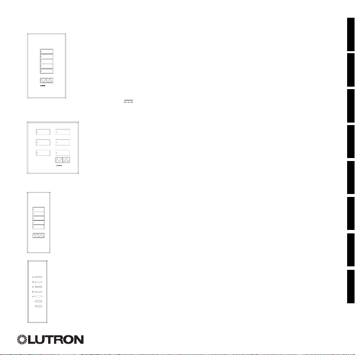
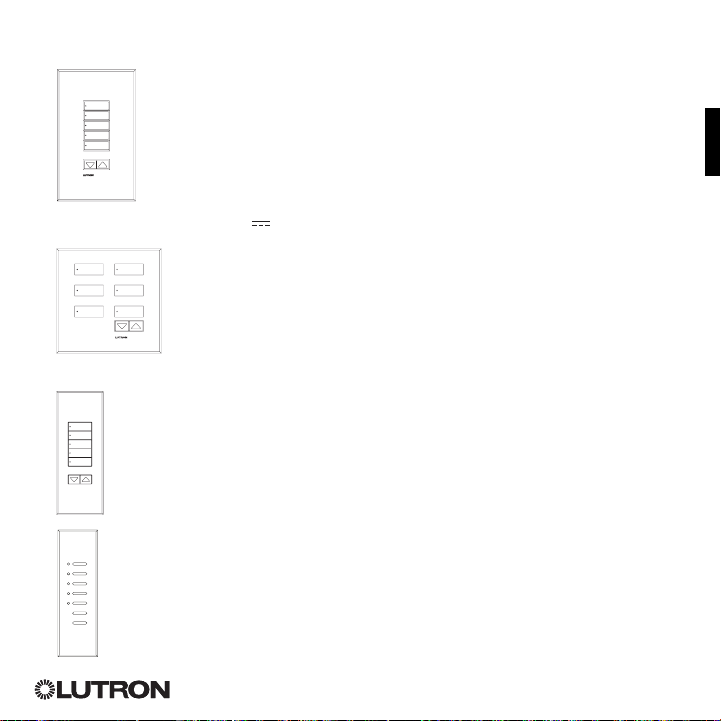
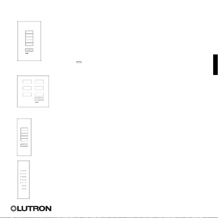
QS Wallstation Models
seeTouch®
Keypads
QSWS2-1B
QSWS2-2B
QSWS2-3B
QSWS2-5B
QSWS2-7B
QSWS2-2BRL
QSWS2-3BRL
QSWS2-5BRL
QSWS2-2BRLIR
QSWS2-3BRLIR
QSWS2-5BRLIR
QSWS2-1RLD
QSWS2-2RLD
QSWS2-3BD
Signature Series
Keypads
QSWAS-1B
QSWAS-2B
QSWAS-3B
QSWAS-5B
QSWAS-7B
QSWAS-2BRL
QSWAS-3BRL
QSWAS-5BRL
QSWAS-1RLD
QSWAS-2RLD
QSWAS-3BD
Notes
Read all instructions carefully before starting
•
installation.
• Lutron recommends that wallstations be installed
by a qualified electrician.
• Use only a cloth with warm water and mild soap to
clean faceplates (no chemical cleaners).
seeTouch®
International Keypads
QSWE-2B
QSWE-3B
QSWE-4B
QSWE-5BRL
QSWE-5BRLIR
QSWE-6BRL
QSWE-7BRL
QSWE-8BRL
QSWE-8BRLIR
QSWE-10BRL
TM
Architrave
Keypads
QSWA-KP5-DN
QSWA-KP5-DW
QSWA-KP7-DN
QSWA-KP7-DW
TM
Overview
• QS wallstations can be programmed to control
lights, shades, or lights and shades.
• Unprogrammed (out-of-box) QS wallstations,
Sivoia® QS shades, GRAFIK Eye® QS control
units, and Energi Savr NodeTM units will all work
together until they are programmed otherwise.
• Contact closure inputs allow operation with
occupancy/vacancy sensors, partitioning, and
more.
QS Link Limits
• The QS wired communication link is limited to
100 devices and 100 zones. Each QS wallstation
counts as 1 device and 0 zones.
• QS wallstations use 1 power draw unit (PDU) on
the QS link. Refer to the QS Link Power Draw
Units specification submittal (Lutron P/N 369405)
and the diagram on the opposite page for more
information concerning Power Draw Units.
Compatible Components
The following devices are compatible with the QS
link. For more information on each, refer to
www.lutron.com/qs
• GRAFIK Eye
• QS wallstations
• Sivoia® QS shades
• QS Interfaces (contact closure, Ethernet/RS232)
• Quantum® system
• Energi Savr NodeTM units
• QS Sensor Module
• QS Keyswitch
2Installation Instructions Occupant Copy
® QS control units
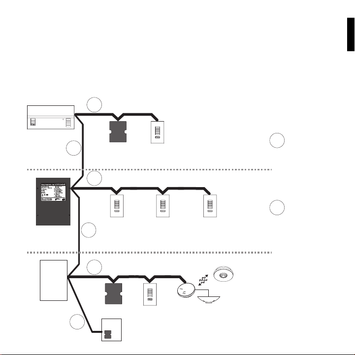
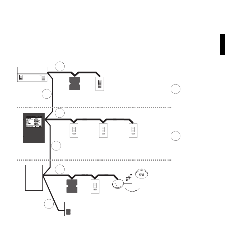
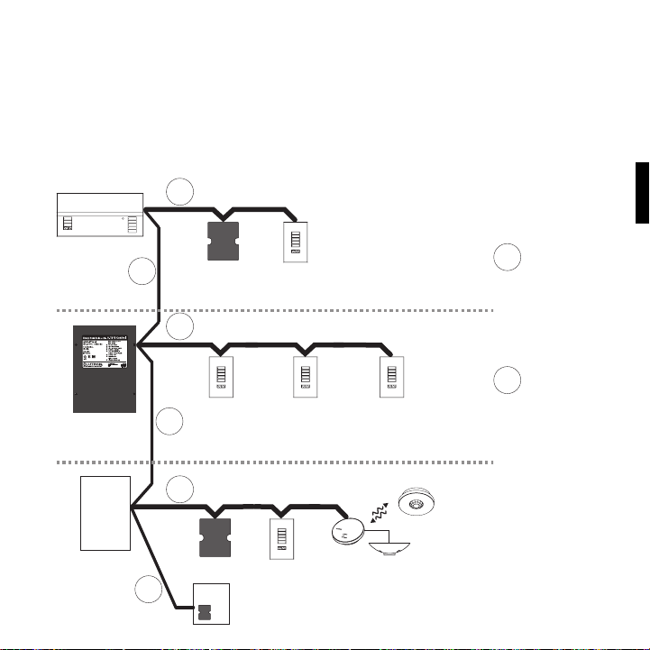
Power Group Wiring Example
On the QS link, there are devices that supply power and devices that consume power. Each device has a
specific number of Power Draw Units (PDUs) it either supplies or consumes. A Power Group consists of one
device that supplies power and one or more devices that consume power; each Power Group may have
only one power-supplying device. Refer to the QS Link Power Draw Units specification submittal
(Lutron P/N 369405) for more information concerning PDUs.
Within Power Groups on the QS link, connect all 4 terminals (1, 2, 3, and 4), shown by the letter A in the
diagram. Between devices on the QS link that supply power, connect only terminals 1, 3, and 4 (NOT
terminal 2), shown by the letter B on the diagram.
Wiring can be T-tapped or daisy-chained.
A
Power Group 1
GRAFIK Eye® QS
control unit
Supplies PDUs
(Do not connect
Terminal 2: V+)
Energi Savr Node
unit
Supplies PDUs
QS Power Supply
Supplies PDUs
(Do not connect
Terminal 2: V+)
LUTRON
B
TM
(Do not connect
Terminal 2: V+)
B
Control Interfaces
Consume PDUs
A
B
A
Wallstations
Consume PDUs
LUTRON LUTRON
LUTRON
® Panel
Quantum
Supplies PDUs
LUTRON
Connect all 4
A
terminals within a
power group:
1: Common
Power Group 2
LUTRON
2: V+
3 and 4: Data
Connect only 3
B
terminals between
power groups:
1: Common
3 and 4: Data
Do not connect
Power Group 3
QS Sensor Module with Occupancy
Sensor
Consume PDUs
3Occupant Copy Installation Instructions
Terminal 2: V+
Wiring/Installation
LUTRON
LUTRON
LUTRONLUTRON
LUTRON
LUTRON
• Refer to the system installation guide and Lutron job
drawings for power cable and data cable (control
link) wiring restrictions and limitations.
• Connect the wallstation to the control link inside the
wallstation’s wallbox or in a junction box (provided
by others).
• Use the wire connector required by local code.
Warning! Shock hazard. May result
in serious injury or death. Always turn
OFF the circuit breaker/MCB or remove
the main fuse from the power line before
doing any work.
1. Turn Power OFF. Turn
power OFF at circuit
breaker/MCB (or remove
fuse).
2. Mount Wallbox. Ensure correct size. See
“Mounting” for details.
3. Prepare Wallstations. Remove the faceplate and
set aside.
4. Prepare wires. Strip insulation from wires so that
4 in (10 mm) of bare wire is exposed.
ON
OFF
ON
OFF
ON
OFF
• Control link wiring must not be run in the same
raceway as line voltage.
• The drain/shield wire must be maintained throughout
the control link. Do not connect the shield to earth/
ground or allow contact with the grounded wallbox.
• Do not connect high-voltage power to lowvoltage ter mi nals. Improper wiring can result in
personal injury or damage to the control or to other
equipment.
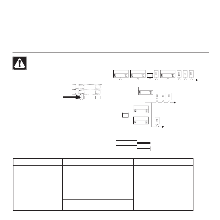
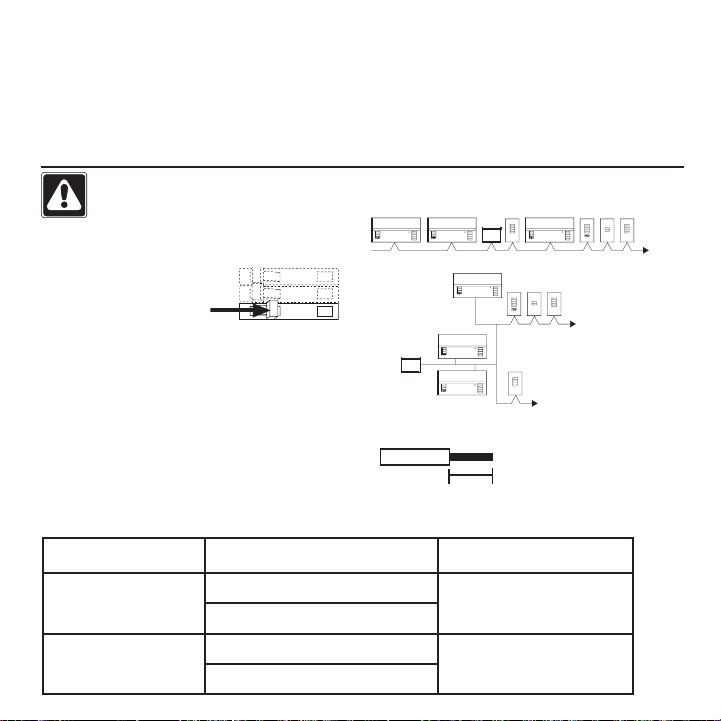
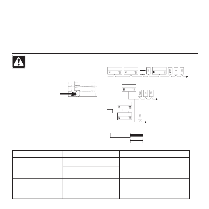
Allowable Wiring Configurations
Daisy chain
LUTRON
LUTRONLUTRON
LUTRON
LUTRON
T-Tap
LUTRON
LUTRON
LUTRON
LUTRON LUTRON LUTRON
LUTRON
LUTRON
LUTRON
Wire Strip length
Wire Sizes (check compatibility in your area)
QS Link Wiring Length Wire Gauge Lutron Cable P/N
Less than 153 m (500 ft) Power (terminals 1 and 2)
153 to 610 m
(500 to 2000 ft)
1 pair 1.0 mm
Data (terminals 3 and 4)
1 twisted, shielded pair 0.5 mm
Power (terminals 1 and 2)
1 pair 4.0 mm
Data (terminals 3 and 4)
1 twisted, shielded pair 0.5 mm
2
(18 AWG) GRX-CBL-346S (non-plenum)
2
(22 AWG)
2
(12 AWG) GRX-CBL-46L (non-plenum)
2
(22 AWG)
GRX-PCBL-346S (plenum)
GRX-PCBL-46L (plenum)
4Installation Instructions Occupant Copy
4 in (10 mm)
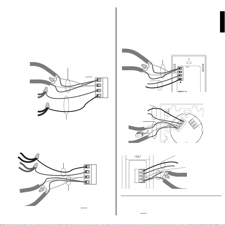
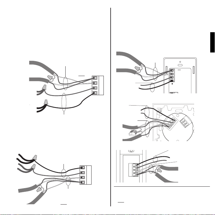
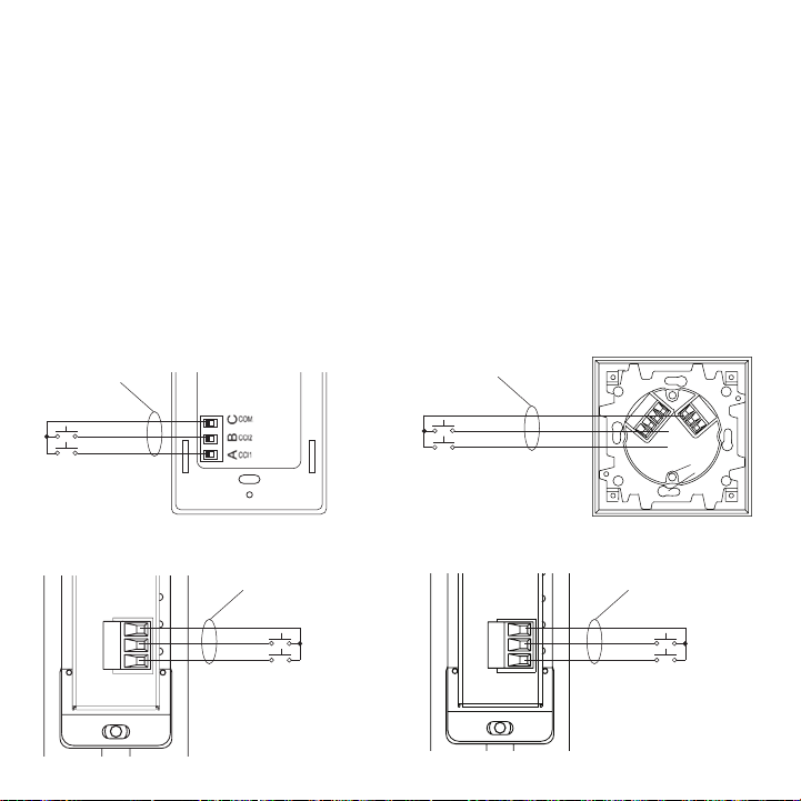
Wiring the QS Link
Connect two 22 AWG (0.5 mm
2
) shielded, twisted
pair wires to terminals 3 and 4 of the wallstation’s
control link connector. Shielding (drain) of the
twisted pair wires must be connected together as
shown, but do not connect the shielding to earth/
ground or the wallstation and do not allow it to
contact the grounded wallbox.
500 to 2000 ft/153 to 610 m
seeTouch®, seeTouch® International
Drain
(2) 12 AWG
(4.0 mm2)
(2) 12 AWG
(4.0 mm2)
Signature Series
TM, ArchitraveTM
SELV / PELV / NEC® Class 2 control
wiring
(2) 18 AWG (1.0 mm2)
1: Common
2: V+
Data link: (1) twisted, shielded
pair
22 AWG (0.5 mm2)
3: MUX
4: MUX
SELV / PELV / NEC® Class 2 control
wiring
(2) 18 AWG (1.0 mm2)
1: Common
2: V+
(2) 12 AWG
(4.0 mm2)
(2) 12 AWG
1
(4.0 mm2)
2
3
4
Connect the appropriate size wires to terminals 1
and 2 for power, according to your link length (see
table opposite).
<500 ft/153 m
seeTouch®
Data link
4
3
2
1
Drain
SELV / PELV / NEC®
Class 2 control
wiring
seeTouch® International
Data
link
®
SELV / PELV / NEC
Class 2 control
wiring
4 3 2 1
4
3
2
1
Drain
Signature SeriesTM, ArchitraveTM
1
2
3
4
SELV / PELV / NEC® Class 2
control wiring
Drain
MUX
MUX
V+
COM
1 2 3 4
C B A
Data link
Drain
Data link: (1) twisted, shielded
pair
22 AWG (0.5 mm2)
3: MUX
4: MUX
Data link: (1) twisted, shielded
pair
22 AWG (0.5 mm2)
3: MUX
5Occupant Copy Installation Instructions
4: MUX
SELV / PELV / NEC® Class 2
control wiring
(2) 18 AWG (1.0 mm2)
1: Common
2: V+
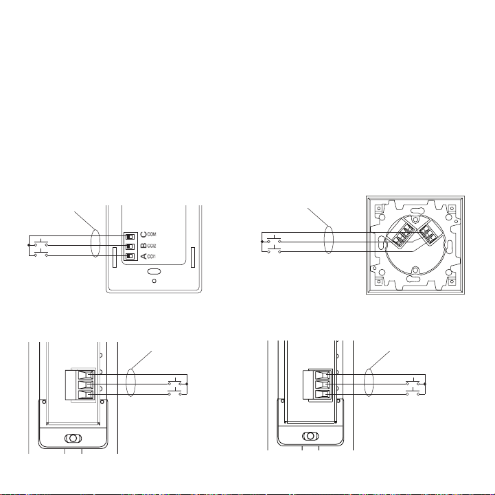
Wiring the Contact Closure Input (CCI)
CO OPERSBURG , PA 18036 USA
:
30 mA
The contact closure inputs must be dry contact
closure, solid state, open collector, or active-low
(NPN)/active-high (PNP) output.
• Open collector NPN or active-low on-state voltage
must be less than 2 V and sink 3.0 mA.
• Open collector PNP or active-high on-state voltage
must be greater than 12 V and source 3.0 mA.
• The outputs must stay in the closed or open states
for at least 60 msec in order to be recognized by
the wallstation.
If there is any question as to whether the third-party
Note: If a wallstation has devices connected
to it through contact closure inputs,
CCI1 “presses” the top button and CCI2
“presses” the bottom button. To change
this behavior, refer to Application Note 428
(seeTouch
at www.lutron.com.
Exception: On a 2-button wallstation
configured for partitioning, panic, or
sequencing functionality, CCI1 closure
action follows the top button and opening
action follows the bottom button.
device generating these outputs is compatible with
these specifications, contact the manufacturer.
seeTouch® seeTouch® International
(3) 18 AWG
(1.0 mm2)
Common
Input 2
Input 1
(3) 18 AWG
2
(1.0 mm
Common
Input 2
Input 1
)
® Advanced Programming Mode)
C B A
4 3 2 1
Signature SeriesTM
Installation Instructions Occupant Copy6
A
B
C
(3) 18 AWG
(1.0 mm2)
Input 1
Input 2
Common
ArchitraveTM
(3) 18 AWG
(1.0 mm2)
A
B
C
Input 1
Input 2
Common
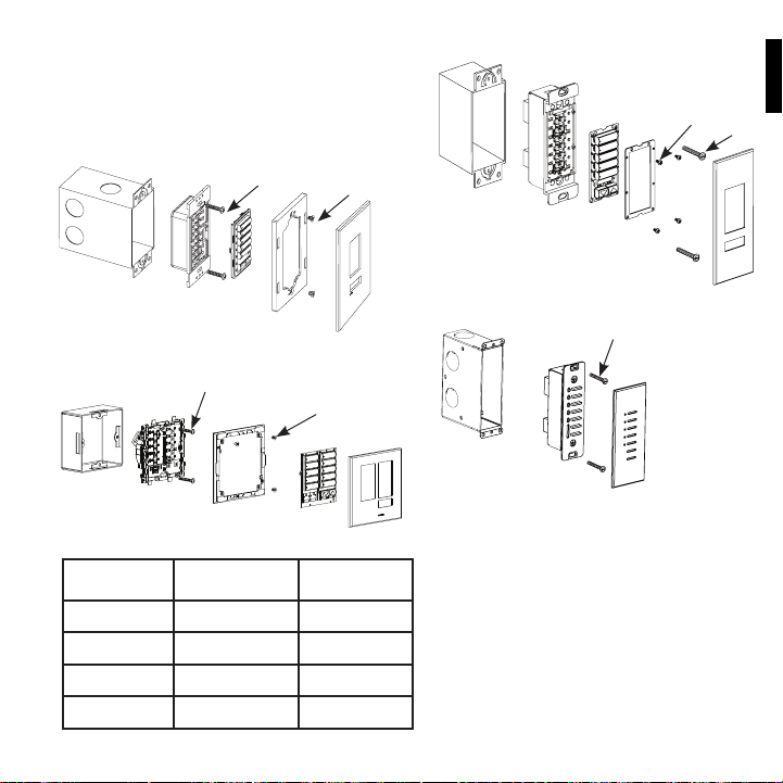
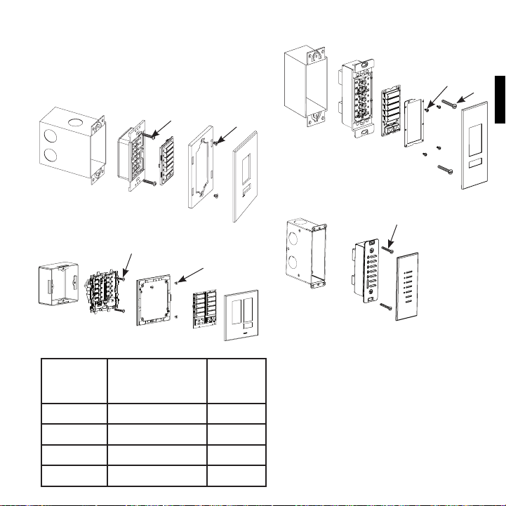
Mounting
Carefully mount and align the wallstation as
shown. Screw top and bottom screw into the
control and wallbox. Replace adapter (for insert
versions; screw to control), button assembly, and
faceplate in the order shown.
seeTouch®
Mounting screws
Adapter
screws
Signature SeriesTM
Wallbox
Control
Buttons
Adapter
Adapter
screws
Mounting
screws
Wallbox
Control
Buttons
Adapter
Faceplate
seeTouch® International
Mounting screws
Adapter screws
Wallbox
Control
Adapter
Buttons
Faceplate
®
®
TM
TM
Wallbox Size
(high x wide x deep)
3.75 x 2.25 x 2.75 in
(95 x 55 x 70 mm)
3 x 3 x 1.5 in
(75 x 75 x 35 mm)
4.5 x 1.5 x 2.75 in
(113 x 39 x 71 mm)
4.5 x 1.25 x 2.75 in
(112 x 32 x 70 mm)
Lutron P/N
241519
241683
WBOX-SA1-Q1
241399
Wallstation Type
seeTouch
seeTouch
International
Signature Series
Architrave
Occupant Copy Installation Instructions7
Faceplate
ArchitraveTM
Mounting screws
Wallbox
Control
Faceplate
Power Up
Turn ON control breaker, or replace main fuse.
Installation is Complete
For Programming functions, see the
QS Wallstation Programming Guide at
www.lutron.com/qs.

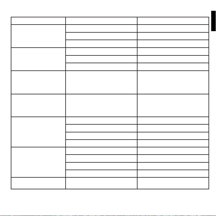
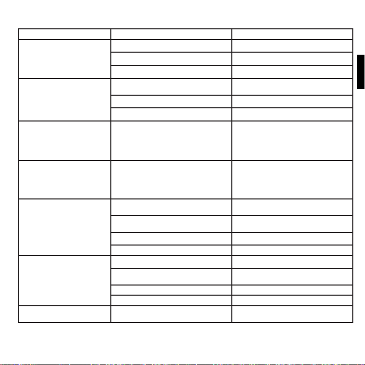
Troubleshooting: LED Functionality
LED Behavior Meaning and Remedy
All Keypad Types
“Reverse Waterfall”
LEDs light beginning at the bottom, continuing to light
until all are on; then LEDs go off beginning at the bottom,
continuing until all are off. Cycle then repeats.
No LED feedback at all, even when a button is pushed. No power to wallstation. Check power wiring.
All LEDs are flashing rapidly. Wallstation is in advanced programming mode. Press and hold the
Shade Keypads
Top and bottom LEDs are flashing together. Keypad is in assignment mode. Press and hold the top and bottom
All LEDs flash 3 times, pause, then repeat. Keypad is in assignment or limit set mode and cannot find or
Top and bottom LEDs light in an alternating pattern (top LED
lights, then goes off, then bottom LED lights, then goes off;
cycle repeats).
Top and bottom LEDs blink slowly, and one other LED blinks
rapidly.
Other Keypads
A single LED is flashing. Keypad is configured for either zone toggle, partitioning, or shade
“Forward Waterfall”
LEDs light and go off in sequence from top to bottom.
Unable to communicate on QS link, or alone on QS link. Check link
wiring.
Another device on QS link is in programming or assignment mode.
Take that device out of programming mode, or put this keypad into
programming mode and then exit programming mode, which turns
off programming mode on all devices.
top and bottom buttons for 3 seconds to exit advanced programming
mode.
buttons for 3 seconds to exit assignment mode.
communicate with any shades assigned to the QS link. Check the
shade wiring.
Wait 60 seconds, and the keypad will automatically return to normal
mode (without any user intervention). Or, press and hold the top and
bottom buttons for 3 seconds to immediately exit the mode.
Keypad is in limit set mode, or another device on the link is in limit
set mode. Press and hold the top and raise buttons for 3 seconds to
exit limit set mode.
Keypad is in preset adjust mode. Press and hold the top and bottom
buttons to exit preset adjust mode.
toggle and is in programming mode. Press and hold the top and
bottom buttons to exit programming mode.
Keypad is configured for scene, panic, sequence, fine tune, or
scene/zone lockout, and is in programming mode. Press and hold
the top and bottom buttons to exit programming mode.
8Installation Instructions Occupant Copy
Troubleshooting: Shade Functions
Symptom Possible Causes Remedy
EDU (electronic drive unit of the
shade) will not move.
EDU (electronic drive unit of the
shade) does not fully open or
fully close.
Shade moves in the opposite
direction when raise/lower
buttons are pushed.
EDU is not powered Check EDU power
Shade fabric is caught on something Check and unbind shade fabric
EDU is not assigned to a keypad Assign the EDU to a keypad
Presets have been set incorrectly Try using raise/lower buttons on keypad
Limits have been set incorrectly Set limits correctly
Shade fabric is caught on something Check and unbind shade fabric
Open and close limits have been reversed Set limits correctly
Keypad LEDs are off and keypad
will not control any shade.
Keypad LEDs are on but keypad
will not control any shade.
Keypad does not operate all the
shades it is assigned to.
Shades in a room move on their
own.
No power is going to keypad Check and wire power to keypad
All presets are set to the same height Try using raise/lower buttons on keypad
Communications link is not wired to the EDU Check and wire the EDU link
EDU has been unassigned from keypad Reassign the EDU to the keypad
Open and close limits are the same Set limits correctly
EDU has been unassigned from keypad Reassign the EDU to the keypad
All presets are set to the same height Try using raise/lower buttons on keypad
EDU is not wired correctly Check and rewire EDU
Keypad is not wired correctly Check and rewire keypad
EDUs are assigned to a keypad in another
room
9Occupant Copy Installation Instructions
Reassign the EDU to the correct keypad
®
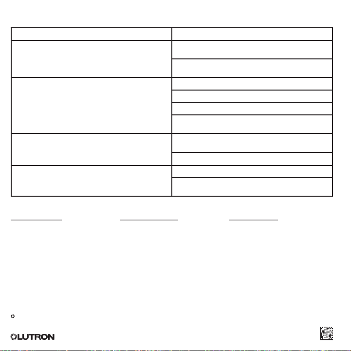
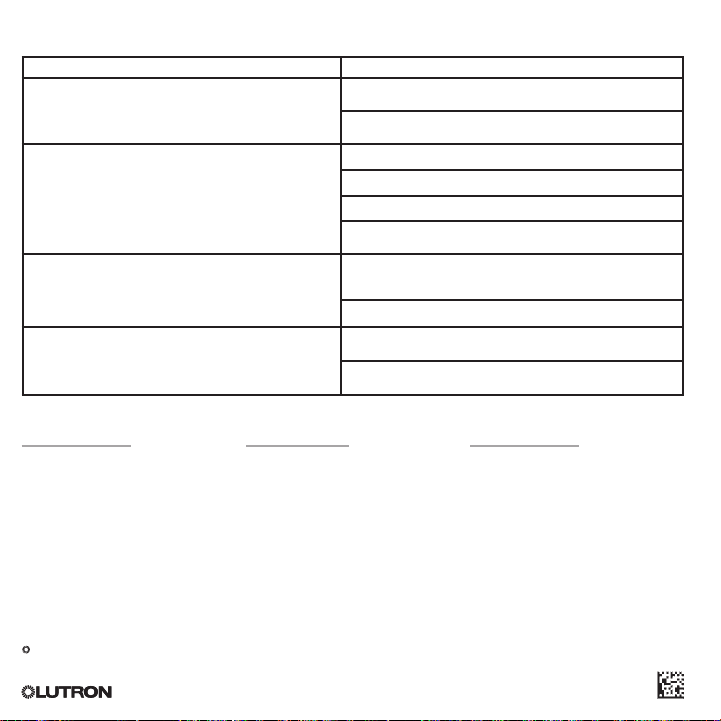
Troubleshooting
Symptom Possible Causes
No communication with GRAFIK Eye
NodeTM unit.
Wallstation buttons do not work; LEDs do not track; wallstation
buttons do not function as intended.
® control unit or Energi Savr
LEDs do not light. Miswire or loose connection at wallstation(s) or processor on the
Contact closure inputs or sensor input do not produce the
desired result in the system.
Internet: www.lutron.com
E-mail: product@lutron.com
WORLD HEADQUARTERS
USA
Lutron Electronics Co., Inc.
7200 Suter Road
Coopersburg, PA
18036-1299
TEL +1.610.282.3800
FAX +1.610.282.1243
Toll-Free 1.888.LUTRON1
Technical Support 1.800.523.9466
North and South America
Technical Hotlines
USA, Canada, Caribbean: 1.800.523.9466
Mexico: +1.888.235.2910
Central/South America: +1.610.282.6701
Warranty: www.lutron.com/TechnicalDocumentLibrary/Warranty_CommercialSystems.pdf
National Electric Code, NEC, and NFPA are registered trademarks of the National Fire Protection
Association, Inc., Quincy, Massachusetts.
Lutron, Lutron, Sivoia, seeTouch, Quantum, and GRAFIK Eye are registered trademarks, and Energi
Savr Node, Signature Series and Architrave are trademarks of Lutron Electron ics Co., Inc.
© 2012–2015 Lutron Electronics Co., Inc.
®
EUROPEAN HEADQUARTERS
United Kingdom
Lutron EA Ltd.
6 Sovereign Close
London
E1W 3JF United Kingdom
TEL +44.(0)20.7702.0657
FAX +44.(0)20.7480.6899
FREEPHONE (UK) 0800.282.107
Technical support +44.(0)20.7680.4481
Miswire or loose connection at the control link data lines 3
and 4.
Wallstation has not been programmed or has been programmed
incorrectly.
Wallstation is miswired.
Wallstation is not powered.
Wallstation is not programmed to the correct device.
Wallstation has not been programmed or has been programmed
incorrectly.
control link common and power connections 1 and 2.
Wallstation has been programmed incorrectly.
Miswire or loose connection at wallstation sensor/CCI connector.
Wallstation has not been programmed or has been programmed
incorrectly.
ASIAN HEADQUARTERS
Singapore
Lutron GL Ltd.
15 Hoe Chiang Road
#07-03 Euro Asia Centre
Singapore 089316
TEL +65.6220.4666
FAX +65.6220.4333
Asia Technical Hotlines
Northern China: 10.800.712.1536
Southern China: 10.800.120.1536
Hong Kong: 800.901.849
Indonesia: 001.803.011.3994
Japan: +81.3.5575.8411
Macau: 0800.401
Singapore: 800.120.4491
Taiwan: 00.801.137.737
Thailand: 001.800.120.665853
Other countries: +65.6220.4666
Lutron Electronics Co., Inc.
P/N 0301783 Rev. A 6/2015
Teclados de pared QS
Guía de instalación
Lea con atención
SELV / PELV / NEC® Class 2
24–36 V 30 mA
Contenido
Descripción general ......................................................................... 2
Ejemplo de cableado del grupo de alimentación ............................... 3
Cableado/Instalación ........................................................................ 4
Montaje ...........................................................................................7
Resolución de problemas ................................................................. 8
Para la programación, consulte la Guía de programación
de botonera de pared QS (P/N 0301639)
en www.lutron.com/qs
Español
Los circuitos de las botoneras de pared se clasifican como SELV / PELV / NEC®
Class 2. Como circuitos de Class 2, cumplen con los requisitos de NFPA
National Electrical Code
requisitos de IEC 60364-4-41, VDE 0100 Parte 410, BS7671:1992 y otras normas
equivalentes. Al instalar y conectar el cableado a estas botoneras de pared,
siga todas las normas de cableado nacionales y/o locales aplicables. Los circuitos
externos conectados a los terminales de entrada, salida y otros terminales
de comunicación de las botoneras de pared deben provenir de una fuente
listado como Class 2 o cumplir los requisitos de los circuitos SELV / PELV, según
®
corresponda en su país.
® (NEC®). Como circuitos SELV / PELV, cumplen con los
® 70,

Modelos de botoneras de pared QS
Botoneras de pared
seeTouch®
QSWS2-1B
QSWS2-2B
QSWS2-3B
QSWS2-5B
QSWS2-7B
QSWS2-2BRL
QSWS2-3BRL
QSWS2-5BRL
QSWS2-2BRLIR
QSWS2-3BRLIR
QSWS2-5BRLIR
QSWS2-1RLD
QSWS2-2RLD
QSWS2-3BD
Botoneras de pared
Signature Series
QSWAS-1B
QSWAS-2B
QSWAS-3B
QSWAS-5B
QSWAS-7B
QSWAS-2BRL
QSWAS-3BRL
QSWAS-5BRL
QSWAS-1RLD
QSWAS-2RLD
QSWAS-3BD
Notas
• Lea detenidamente todas las instrucciones antes
de comenzar con la instalación.
• Lutron recomienda que las botoneras de pared
sean instaladas por un electricista competente.
• Utilice únicamente un paño con agua tibia
y jabón suave para limpiar las placas frontales
(no utilice limpiadores químicos).
Botoneras de pared
seeTouch® Internacional
QSWE-2B
QSWE-3B
QSWE-4B
QSWE-5BRL
QSWE-5BRLIR
QSWE-6BRL
QSWE-7BRL
QSWE-8BRL
QSWE-8BRLIR
QSWE-10BRL
Botoneras de pared
Architrave
TM
QSWA-KP5-DN
QSWA-KP5-DW
QSWA-KP7-DN
QSWA-KP7-DW
TM
Descripción general
• Las botoneras de pared QS se pueden programar
para controlar luces, cortinas, o luces
y cortinas.
• Las botoneras de pared QS, cortinas Sivoia® QS,
unidades de control GRAFIK Eye® y unidades
Energi Savr NodeTM no programadas (como vienen
de fábrica) funcionarán en conjunto, a menos que
se los programe de otra manera.
• Las entradas de contacto seco permitirán
el funcionamiento con sensores de presencia/
vacancia, partición y mucho más.
Límites del enlace QS
• El enlace de comunicación cableado QS
puede tener hasta 100 dispositivos y 100 zonas.
Cada botonera de pared QS cuenta
como 1 dispositivo y 0 zonas.
• Las botoneras de pared QS utilizan 1 unidad
de consumo de energía (PDU) en el enlace QS.
Para obtener más información sobre las unidades
de consumo de energía, consulte el documento
de especificaciones “Unidades de consumo de
energía del enlace QS” (Lutron P/N 369405) y el
diagrama de la página opuesta.
Componentes compatibles
Los siguientes dispositivos son compatibles
con el enlace QS. Para obtener más información
sobre cada dispositivo, visite www.lutron.com/qs
• Unidades de control GRAFIK Eye
• Botoneras de pared QS
• Cortinas Sivoia® QS
• Interfases QS (contacto seco, Ethernet/RS232)
• Sistema Quantum®
• Unidades Energi Savr NodeTM
• Módulo de sensor QS
• Interruptor QS
2Instrucciones de instalación Copia para el ocupante
® QS
Ejemplo de cableado del grupo de alimentación
En el enlace QS, hay dispositivos que proporcionan alimentación y otros que la consumen. Cada dispositivo
tiene un número específico de las unidades de consumo de energía (PDU) que suministra o consume.
Un grupo de alimentación consta de un dispositivo que alimenta y uno o más dispositivos que consumen
energía; cada grupo de alimentación solo puede tener un dispositivo de alimentación. Consulte el documento
de especificaciones “Unidades de consumo de energía en el enlace QS” (Lutron P/N 369405) para obtener
más información sobre las unidades de consumo de energía (PDU).
En los grupos de alimentación del enlace QS, conecte los cuatro terminales (1, 2, 3 y 4) según se muestra
en la letra A del diagrama. Entre los dispositivos del enlace QS que suministran alimentación, conecte solo
los terminales 1, 3 y 4 (NO conecte el terminal 2) según se indica en la letra B del diagrama.
El cableado puede conectarse en cadena o en derivación en T.
A
Grupo de alimentación 1
Unidad de control
GRAFIK Eye® QS
Suministra PDU
(No conecte
el terminal 2: V+)
Unidad
Energi Savr Node
Suministra PDU
Fuente de
alimentación QS
Suministra PDU
(No conecte
el terminal 2: V+)
LUTRON
B
TM
(No conecte
el terminal 2: V+)
B
Interfases de
control
Consume PDU
A
B
A
Botoneras de
pared
Consume PDU
LUTRON LUTRON
LUTRON
Panel Quantum
Suministra PDU
LUTRON
Conecte los
A
4 terminales dentro
de un grupo
de alimentación:
Grupo de alimentación 2
1: Común
2: V+
3 y 4: Datos
LUTRON
Conecte solo
B
3 terminales
entre los grupos
de alimentación:
1: Común
Grupo de alimentación 3
3 y 4: Datos
No conecte
el terminal
2: V+
Módulo de sensor QS con sensor de presencia
Consume PDU
®
3Copia para el ocupante Instrucciones de instalación
Cableado/Instalación
LUTRON
LUTRON
LUTRONLUTRON
LUTRON
LUTRON
• Consulte la guía de instalación del sistema y los diagramas
de trabajo de Lutron para conocer las restricciones
y limitaciones del cable de alimentación y el cableado
de datos (enlace del control).
Conecte la botonera de pared al enlace del control
•
dentro de la caja de empotrar de la botonera de pared
o en una caja de conexiones (de otro proveedor).
Utilice el conector de cable exigido por los códigos locales.
•
¡Advertencia! Riesgo de descarga
eléctrica. Puede ocasionar lesiones
graves o la muerte. APAGUE siempre
el cortacircuitos/microcortacircuitos o retire
el fusible principal de la línea de alimentación antes
de realizar cualquier trabajo.
1. Desconecte
la alimentación.
Desconecte la alimentación
en el cortacircuitos/
microcortacircuitos
(o retire el fusible).
2. Monte la caja de empotrar. Asegurar el tamaño
correcto. Vea “Montaje” para más detalles.
3. Prepare las botoneras de pared. Retire la placa
frontal y apártela.
4. Prepare los cables. Pele el aislamiento de los
cables de modo que queden expuestos 10mm
(0.375 pulg) del cable.
Tamaños de cable (verifique la compatibilidad en su área)
Longitud del cableado
del enlace QS
Menos de 153m
(500pi)
153 a 610m
(500 a 2 000pi)
ON
OFF
ON
OFF
ON
OFF
Calibre del cable Cable Lutron P/N
Alimentación (terminales 1 y 2)
1 par de 1,0 mm
Datos (terminales 3 y 4)
1 par trenzado, blindado de 0,5 mm
Alimentación (terminales 1 y 2)
1 par de 4,0mm
Datos (terminales 3 y 4)
1 par trenzado, blindado de 0,5 mm
2
(18 AWG) GRX-CBL-346S (sin plenum)
2
(12 AWG) GRX-CBL-46L (sin plenum)
• El cableado del enlace del control no debe correr
en el mismo conducto que la tensión de línea.
El cable de descarga/blindaje debe ser continuo a lo largo
•
del enlace de control. No conecte el blindaje a tierra/masa
ni permita que entre en contacto con la caja de empotrar
conectada a tierra.
No conecte la alimentación de alto voltaje a terminales
•
de bajo voltaje. Un cableado incorrecto puede causar
lesiones personales o daños al control o a otros equipos.
Configuraciones de cableado permitidas
En serie
LUTRON
LUTRONLUTRON
LUTRON
Derivación
en T
LUTRON
LUTRON
LUTRON LUTRON LUTRON
LUTRON
LUTRON
LUTRON
LUTRON
LUTRON
Longitud de la sección pelada del cable
10 mm (0.375 pulg)
2
(22 AWG)
2
(22 AWG)
GRX-PCBL-346S (con plenum)
GRX-PCBL-46L (con plenum)
4Instrucciones de instalación Copia para el ocupante
Cableado del enlace QS
Conecte dos cables de par trenzado y blindado de
2
0,5mm
(22 AWG) a los terminales 3 y 4 del conector
de enlace del control de la botonera de pared. Los
blindajes (la descarga) de los cables de par trenzado
se deben conectar juntos como se muestra en la
ilustración, pero no conecte el blindaje a tierra/masa ni
a la botonera de pared, ni permita que haga contacto
con la caja de empotrar conectada a tierra.
153 a 610 m/500 a 2 000 pi
seeTouch®, seeTouch® Internacional
(2) 4,0 mm2
(12 AWG)
(2) 4,0 mm2
(12 AWG)
Enlace de datos: (1) par trenzado y
Descarga
Cableado de control
SELV / PELV / NEC® Class 2
(2) 1,0 mm2 (18 AWG)
1: Común
2: V+
blindado
0,5 mm2 (22 AWG)
3: MUX
4: MUX
4
3
2
1
Conecte los cables del tamaño apropiado a las
terminales 1 y 2 para la alimentación, de acuerdo
con la longitud del enlace (consulte la tabla en la
página opuesta).
< 153 m/500 pi
seeTouch®
Enlace de
Descarga
Cableado
de control
SELV / PELV /
® Class 2
NEC
datos
4
MUX
3
MUX
V+
2
COM
1
1 2 3 4
seeTouch® Internacional
Cableado
de control
SELV / PELV / NEC
Class 2
Enlace de datos
®
4 3 2 1
C B A
Descarga
Signature Series
Descarga
TM, ArchitraveTM
Cableado de control
SELV / PELV / NEC® Class 2
(2) 1,0 mm2 (18 AWG)
1: Común
2: V+
Enlace de datos:
(1) par trenzado y blindado
0,5 mm2 (22 AWG)
3: MUX
4: MUX
(2) 4,0 mm2
(12 AWG)
(2) 4,0 mm2
1
(12 AWG)
2
3
4
Signature SeriesTM, ArchitraveTM
1
2
3
4
Enlace de datos: (1) par
trenzado y blindado 0,5 mm2
(22 AWG)
3: MUX
4: MUX
Cableado de control
SELV / PELV / NEC
® Class 2
Enlace de datos
Descarga
Cableado de control SELV / PELV / NEC®
Class 2 (2) 1,0 mm2
(18 AWG)
1: Común
2: V+
5Copia para el ocupante Instrucciones de instalación
Cableado de la entrada de contacto seco (CCI)
CO OPERSBURG , PA 18036 USA
:
30 mA
Las entradas deben ser de cierre por contacto
seco, de estado sólido, de colector abierto,
o salida de activo bajo (NPN)/activo alto (PNP).
• El voltaje del colector abierto NPN o bajo en activo
en estado encendido debe ser inferior a 2V
y con una capacidad de corriente de sumidero
de 3,0mA.
• El voltaje del colector abierto PNP activo en alto
en estado encendido debe ser mayor a 12V
y fuente de 3,0mA.
• Las salidas tienen que permanecer al menos
60 milisegundos en estado cerrado o abierto
para ser reconocidas por la botonera de pared.
Si hay alguna pregunta sobre si el dispositivo
de un tercero que genera estas salidas
es compatible con estas especificaciones,
comuníquese con el fabricante.
Nota: Si una botonera de pared tiene dispositivos
conectados a ella a través de entradas
de contacto seco, CCI1 “presiona” el botón
superior y CCI2 “presiona” el botón inferior.
Para cambiar este comportamiento,
consulte la Nota de aplicación 428 (Modo
de programación avanzada de seeTouch® )
en www.lutron.com.
Excepción: En una botonera de pared de
dos botones configurada para las funciones
de partición, pánico o secuenciación,
la acción de cierre CCI1 sigue al botón
superior y la acción de abertura sigue
al botón inferior.
seeTouch® seeTouch® Internacional
2
(3) 1,0 mm2
(18 AWG)
Común
Entrada 2
Entrada 1
1,0 mm
(18 AWG)
Común
Entrada 2
Entrada 1
C B A
4 3 2 1
Signature SeriesTM
Instrucciones de instalación Copia para el ocupante6
A
B
C
(3) 1,0 mm2
(18 AWG)
Entrada 1 Entrada 1
Entrada 2
Común Común
ArchitraveTM
(3) 1,0 mm2
(18 AWG)
A
B
C
Entrada 2
Montaje
Monte y alinee cuidadosamente la botonera de
pared como se muestra. Ajuste los tornillos superior
e inferior en el control y la caja de empotrar. Vuelva
a colocar el adaptador (para versiones de inserción;
atornille al control) el montaje de botones y la placa
frontal en el orden que se muestra.
®
seeTouch
Tornillos de
montaje
Tornillos
del
adaptador
Signature SeriesTM
Caja de
empotrar
Control
Botones
Adaptador
Tornillos del
adaptador
Tornillos
de
montaje
Caja de
empotrar
Control
Botones
Adaptador
Botones
Placa frontal
Tornillos del
adaptador
seeTouch® Internacional
Caja de
empotrar
Control
Tornillos de montaje
Adaptador
Placa frontal
Tipo de
botonera de
pared
seeTouch
seeTouch
Internacional
Signature
TM
Series
Architrave
Copia para el ocupante Instrucciones de instalación7
Tamaño de la Caja de
Empotrar
(altura x ancho x
profundidad)
95 x 55 x 70 mm
®
(3,75 x 2,25 x 2,75 pulg)
®
75 x 75 x 35 mm
(3 x 3 x 1,5 pulg)
113 x 39.x 71 mm
(4,5 x 1,5 x 2,75 pulg)
112 x 32 x 70 mm
TM
(4,5 x 1,25 x 2,75 pulg)
Lutron P/N
241519
241683
WBOX-SA1-Q1
241399
Placa frontal
ArchitraveTM
Tornillos de montaje
Caja de
empotrar
Control
Placa frontal
Encendido
Conecte el cortacircuitos o vuelva a colocar
el fusible principal.
La instalación está terminada
Para programar las funciones, consulte la Guía
de programación de botonera de pared QS en
www.lutron.com/qs.

Resolución de problemas: Funciones de los indicadores LED
Comportamiento de los indicadores LED Significado y solución
Todos los tipos de botoneras
“Cascada invertida”
Los indicadores LED comienzan a encenderse desde abajo
hasta que todos quedan encendidos; luego se apagan desde
abajo hasta que todos quedan apagados. Luego se repite
el ciclo.
No hay respuesta de los indicadores LED,
ni siquiera al presionar un botón.
Todos los indicadores LED parpadean rápidamente. La botonera de pared está en modo de programación avanzada. Mantenga
Botoneras de cortinas
Los indicadores LED superior e inferior parpadean juntos. La botonera está en el modo de asignación. Mantenga presionados los botones
Todos los indicadores LED parpadean 3 veces,
hacen una pausa y luego repiten.
Los indicadores LED superior e inferior se encienden
de manera alternada (el indicador LED superior se enciende,
luego se apaga, luego se enciende el indicador LED inferior,
luego se apaga; el ciclo se repite).
Los indicadores LED superior e inferior parpadean lentamente,
y otro indicador LED parpadea rápidamente.
Otras botoneras
Un solo indicador LED parpadea. La botonera está configurada para conmutación de zona, partición o
“Cascada frontal”
Los indicadores LED se encienden y se apagan
en una secuencia de arriba hacia abajo.
No hay comunicación en el enlace QS o solo en el enlace QS.
Verifique el cableado del enlace.
No llega energía a la botonera de pared. Verifique el cableado de la alimentación.
Otro dispositivo en el enlace QS está en el modo de programación o asignación.
Quite ese dispositivo del modo de programación o coloque esta botonera en el
modo de programación y luego salga del modo de programación; esto apagará
el modo de programación en todos los dispositivos.
presionados los botones superior e inferior durante 3 segundos para salir del
modo de programación avanzado
superior e inferior durante 3 segundos para salir del modo de asignación.
La botonera está en modo de asignación o ajuste de límites y no puede
encontrar ni comunicarse con cortinas asignadas al enlace QS.
Verifique el cableado de las cortinas.
Espere 60 segundos y la botonera volverá al modo normal automáticamente
(sin la intervención del usuario). O bien, mantenga presionados los botones
superior e inferior durante 3 segundos para salir del modo de inmediato.
La botonera está en el modo de ajuste de límites; o bien, otro dispositivo
en elenlace está en el modo de ajuste de límites. Mantenga presionados
los botones superior y aumentar durante 3 segundos para salir del modo
de ajuste de límites.
La botonera está en el modo de ajuste de niveles predefinidos. Mantenga
presionados los botones superior e inferior para salir del modo de ajuste de
niveles predefinidos.
conmutación de cortinas y está en el modo de programación. Mantenga
presionados los botones superior e inferior para salir del modo de
programación.
La botonera está configurada para escena, pánico, secuencia, ajuste fino
o bloqueo de escena/zona, y está en modo de programación. Mantenga
presionados los botones superior e inferior para salir del modo de
programación.
8Instrucciones de instalación Copia para el ocupante
.
Resolución de problemas: Funciones de las cortinas
Síntomas Posibles causas Solución
La EDU (unidad de drive electrónico
de la cortina) no se mueve.
La EDU (unidad de drive electrónico
de la cortina) no se abre ni se cierra
totalmente.
La cortina se mueve en la dirección
opuesta cuando se presionan los
botones aumentar/disminuir.
La EDU no está conectada a la alimentación Verifique la alimentación de la EDU
La tela de la cortina está atrapada en algo Verifique y destrabe la tela de la cortina
La EDU no está asignada a una botonera Asigne la EDU a una botonera
Los niveles predefinidos han sido configurados
de forma incorrecta
Los límites están configurados de forma incorrecta Configure los límites correctamente
La tela de la cortina está atrapada en algo Verifique y destrabe la tela de la cortina
Los límites de abierta y cerrada están invertidos Configure los límites correctamente
Intente usar los botones de aumentar/disminuir
en la botonera
Los indicadores LED de la botonera
están apagados y la botonera no
controla ninguna cortina.
Los indicadores LED de la botonera
están encendidos pero la botonera
no controla ninguna cortina.
El teclado no opera todas las cortinas
a las que está asignado.
Las cortinas de una habitación
se mueven solas.
No llega la alimentación a la botonera Verifique la alimentación del cable a la botonera
Todos los niveles predefinidos están configurados
a la misma altura
El enlace de comunicaciones no está cableado
a la EDU
La EDU ha sido desasignada desde la botonera Reasigne la EDU a la botonera
Los límites de abierta y cerrada son los mismos Configure los límites correctamente
La EDU ha sido desasignada desde la botonera Reasigne la EDU a la botonera
Todos los niveles predefinidos están configurados
a la misma altura
La EDU no está cableada correctamente Verifique y vuelva a cablear la EDU
La botonera no está cableada correctamente Verifique y vuelva a cablear la botonera
Las EDU están asignadas a una botonera
de otra habitación
9Copia para el ocupante Instrucciones de instalación
Intente usar los botones de aumentar/disminuir
en la botonera
Verifique y cablee el enlace de la EDU
Intente usar los botones de aumentar/disminuir
en la botonera
Reasigne la EDU a la botonera correcta
®
Resolución de problemas
Síntomas Posibles causas
No hay comunicación con la unidad de control GRAFIK Eye®
ni la unidad Energi Savr NodeTM.
Los botones de la botonera de pared no funcionan, los indicadores
LED no realizan ningún seguimiento; los botones de la botonera
de pared no funcionan de la manera prevista.
Los indicadores LED no se encienden. Error de cableado o mala conexión en la(s) botonera(s) o en el procesador
Las entradas de contacto seco o del sensor no producen
los resultados deseados en el sistema.
Internet: www.lutron.com
Correo electrónico: product@lutron.com
SEDE CENTRAL MUNDIAL
E.U.A
Lutron Electronics Co., Inc.
7200 Suter Road
Coopersburg, PA
18036-1299
TEL +1.610.282.3800
FAX +1.610.282.1243
Número gratuito 1.888.LUTRON1
Soporte Técnico 1.800.523.9466
América del Norte y América del Sur
Líneas de Asistencia Técnica
E.U.A, Canadá y el Caribe: 1.800.523.9466
México: +1.888.235.2910
América Central/América del Sur: +1.610.282.6701
Garantía: www.lutron.com/TechnicalDocumentLibrary/Warranty_CommercialSystems.pdf
National Electric Code, NEC y NFPA son marcas comerciales registradas de la National Fire Protection
Association, Inc., Quincy, Massachusetts.
Lutron, Lutron, Sivoia, seeTouch, Quantum, y GRAFIK Eye son marcas registradas y Energi Savr Node,
Architrave, y Signature Series son marcas de Lutron Electronics Co., Inc.
© 2012–2015 Lutron Electronics Co., Inc.
®
SEDE CENTRAL EROPEA
Reino Unido
Lutron EA Ltd.
6 Sovereign Close
Londres
E1W 3JF Reino Unido
TEL +44.(0)20.7702.0657
FAX +44.(0)20.7480.6899
LLAMADA GRATUITA (Reino Unido): 0800.282.107
Soporte Técnico: +44.(0)20.7680.4481
Error de cableado o mala conexión en las líneas de datos 3 y 4 del enlace
de control.
No se ha programado la botonera de pared o se programó de manera
incorrecta.
La botonera de pared está cableada erróneamente.
La botonera de pared no está conectada a la alimentación.
La botonera de pared no está programada con el dispositivo correcto.
No se ha programado la botonera de pared o se programó de manera
incorrecta.
en las conexiones 1 y 2 de la alimentación y el común del enlace de
control.
La botonera de pared se programó de forma incorrecta.
Error de cableado o mala conexión en el conector de CCI/sensor
de la botonera de pared.
No se ha programado la botonera de pared o se programó de
manera incorrecta.
SEDE CENTRAL ASIÁTICA
Singapur
Lutron GL Ltd.
15 Hoe Chiang Road
07-03 Euro Asia Centre
Singapur 089316
TEL +65.6220.4666
FAX +65.6220.4333
Líneas de Asistencia Técnica en Asia
Norte de China: 10.800.712.1536
Sur de China: 10.800.120.1536
Hong Kong: 800.901.849
Indonesia: 001.803.011.3994
Japón: +81.3.5575.8411
Macao: 0800.401
Singapur: 800.120.4491
Taiwán: 00.801.137.737
Tailandia: 001.800.120.665853
Otros países: +65.6220.4666
Lutron Electronics Co., Inc.
P/N 0301783 Rev. A 6/2015
QS Bedienstellen
Installationsanleitung
SELV / PELV / NEC® Class 2
24–36 V 30 mA
Inhalt
Übersicht ......................................................................................... 2
Beispiel zur Gruppierung der Stromversorgungen ............................ 3
Anschluss/Installation ...................................................................... 4
Montage .......................................................................................... 7
Fehlersuche ..................................................................................... 8
Zur Programmierung siehe die Programmieranleitung
für QS Bedienstellen (Bestell-Nr. 0301639)
auf www.lutron.com/qs
Die Kreise, in denen sich Bedienstellen befinden, werden als
/
SELV / PELV
sie den Anforderungen
Schutzkleinspannungskreise mit Schutzerdung (SELV / PELV) genügen sie
den Anforderungen IEC 60364-4-41, VDE 0100 Teil 410, BS7671:1992 und
anderen gleichwertigen Normen und Standards. Während der Installation und
Verdrahtung der Zusatzgeräte befolgen Sie alle im
oder örtlichen Verdrahtungsvorschriften. Externe Kreise,
oder andere Schnittstellen der Zusatzgeräte angeschlossen werden, müssen der
Kategorie 2 entsprechen oder allen in Ihrem Land geltenden Anforderungen an
®
Schutzkleinspannungskreise mit Schutzerdung entsprechen.
NEC® Class 2 eingestuft. Als Kreise der Kategorie 2 genügen
NFPA® 70, National Electrical Code® (NEC®). Als
jeweiligen Land geltenden und/
Bitte lesen
die an Eingang, Ausgang
Deutsch

QS Bedienstellen-Modelle
seeTouch®
Bedienstellen
QSWS2-1B
QSWS2-2B
QSWS2-3B
QSWS2-5B
QSWS2-7B
QSWS2-2BRL
QSWS2-3BRL
QSWS2-5BRL
QSWS2-2BRLIR
QSWS2-3BRLIR
QSWS2-5BRLIR
QSWS2-1RLD
QSWS2-2RLD
QSWS2-3BD
Signature Series
Bedienstellen
QSWAS-1B
QSWAS-2B
QSWAS-3B
QSWAS-5B
QSWAS-7B
QSWAS-2BRL
QSWAS-3BRL
QSWAS-5BRL
QSWAS-1RLD
QSWAS-2RLD
QSWAS-3BD
Hinweise
• Lesen Sie alle Anweisungen sorgfältig durch,
bevor Sie mit der Installation beginnen.
• Lutron empfiehlt, dass die Bedienstellen
nur von Fachpersonal installiert werden.
• Nehmen Sie zur Reinigung der Abdeckungen
ausschließlich einen Lappen mit warmem
Wasser und mit Seifenlauge
(keine chemischen Reinigungsmittel).
TM
seeTouch®
Internationale
Bedienstellen
QSWE-2B
QSWE-3B
QSWE-4B
QSWE-5BRL
QSWE-5BRLIR
QSWE-6BRL
QSWE-7BRL
QSWE-8BRL
QSWE-8BRLIR
QSWE-10BRL
Architrave
Bedienstellen
TM
QSWA-KP5-DN
QSWA-KP5-DW
QSWA-KP7-DN
QSWA-KP7-DW
Übersicht
• QS Bedienstellen können zur Steuerung von
Beleuchtung, Rollos oder von Beleuchtung und
Rollos programmiert werden.
• Unprogrammierte QS Bedienstellen, Sivoia® QS
Rollos, GRAFIK Eye® QS Steuergeräte und
Energi Savr NodeTM Geräte arbeiten alle
zusammen, solange sie nicht anderweitig
programmiert werden.
• Potentialfreie Eingänge ermöglichen Betrieb
mit Präsenzmeldern, Trennwänden u.a.
QS-Bus-Beschränkungen
• Der verdrahtete QS-Kommunikationsbus ist auf
100 Geräte und 100 Zonen begrenzt. Jede QS
Bedienstelle zählt als 1 Gerät und 0 Zonen.
• QS Bedienstellen verbrauchen 1
Stromversorgungseinheit am QS-Bus. Weitere
Informationen zu Stromversorgungseinheiten
finden Sie im Datenblatt zu QS-BusStromversorgungseinheiten
(Lutron-Bestell-Nr. 369405) und auf der Darstellung
auf der gegenüberliegenden Seite.
Kompatible Komponenten
Die folgenden Geräte sind mit dem QS-Bus
kompatibel. Weitere Informationen finden
Sie auf www.lutron.com/qs
• GRAFIK Eye® QS Steuergeräte
• QS Bedienstellen
• Sivoia® QS Rollos
• QS-Schnittstellen (potentialfreie Kontakte,
Ethernet/RS232)
• Quantum® System
• Energi Savr NodeTM Gerät
• QS-Sensormodul
• QS-Schlüsselschalter
2Installationsanweisungen Benutzerexemplar
Beispiel zur Gruppierung der Stromversorgungen
Am QS-Bus befinden sich Geräte, die Strom liefern, und Geräte, die Strom verbrauchen. Jedes Gerät hat
eine bestimmte Anzahl von Stromeinheiten, die es entweder liefert oder verbraucht. Eine Gruppe besteht
aus einem Gerät, das Strom liefert, und einem oder mehreren Geräten, die Strom verbrauchen. Jede
Leistungsgruppe darf nur ein stromlieferndes Gerät haben. Weitere Informationen zu Stromversorgungseinheiten
finden Sie im Datenblatt zu QS-Bus-Stromversorgungseinheiten (Lutron-Bestell-Nr. 369405).
Verbinden Sie innerhalb der Gruppen am QS-Bus alle 4 Klemmen (1, 2, 3 und 4), die in der Zeichnung mit
dem Buchstaben A gekennzeichnet sind. Verbinden Sie zwischen stromliefernden Geräten am QS-Bus nur
die Klemmen 1, 3 und 4 (NICHT Klemme 2), die in der Zeichnung mit dem Buchstaben B gekennzeichnet sind.
Der Anschluss kann sternförmig oder in Reihe vorgenommen werden.
A
Gruppe 1
GRAFIK Eye® QS
Steuergerät
Liefert
Stromver-
sorgungseinheiten
Energi Savr Node
Gerät
Liefert Stromversorgungseinheiten
QS-Stromversorgungsgerät
Liefert Stromversorgungseinheiten
LUTRON
(Klemme 2 nicht
anschließen: V+)
TM
(Klemme 2 nicht
anschließen: V+)
Steuer-Schnittstellen
B
Verbrauchen
Stromversorgungseinheiten
A
B
(Klemme 2 nicht
anschließen: V+)
A
B
LUTRON
Bedienstellen
Verbrauchen
Stromversorgungseinheiten
LUTRON LUTRON
LUTRON
Quantum
® Schaltschrank liefert
Stromversorgungseinheiten
Alle 4 Klemmen
A
innerhalb einer
Gruppe
anschließen:
Gruppe 2
1: M asse
2: V+
3 und 4: Daten
B
LUTRON
Nur 3 Klemmen
zwischen Gruppen
anschließen:
1: M asse
3 und 4: Daten
Gruppe 3
Klemme 2 nicht
anschließen:
V+
QS-Sensormodul mit Präsenzmelder
Verbrauchen
Stromversorgungseinheiten
3Benutzerexemplar Installationsanweisungen
Anschluss/Installation
LUTRON
LUTRON
LUTRONLUTRON
LUTRON
LUTRON
• Die Systeminstallationsanleitung und Lutrons
Schaltpläne zur Verkabelung der Starkstromund Datenleitungen (Bus-Leitung) enthalten die
für die Verkabelung geltenden Grenzen und
Beschränkungen.
• Die Bedienstelle muss innerhalb der UP-Dose der
Bedienstelle oder in einer Verteilerdose (bauseits) an
die Busleitung angeschlossen werden.
• Verwenden Sie Klemmen, die gesetzlich
vorgeschrieben sind.
Achtung! Stromschlaggefahr. Gefahr
schwerer oder tödlicher Verletzungen.
Vor allen Arbeiten muss immer der
Sicherungsautomat ausgeschaltet bzw.
die Hauptsicherung entfernt werden.
1. Schalten Sie den Strom
AUS. Schalten Sie die
Sicherungsautomaten aus
oder entfernen Sie die
Sicherungen.
2. Installation der UP-Dose. Stellen Sie sicher die
richtige Größe. Siehe “Montage” für Einzelheiten.
3. Vorbereitung der Bedienstellen. Nehmen Sie
die Frontplatte ab und legen Sie sie zur Seite.
4. Vorbereitung der Leitungen. Entfernen Sie
von den Drähten 10 mm der Isolierung.
ON
OFF
ON
OFF
ON
OFF
Die Busleitungen dürfen nicht zusammen mit
•
Netzleitungen
•
Die Schirmleitung muss entlang der gesamten Busleitung
geführt werden. Verbinden Sie die Schirmleitung nicht
mit Erde/Masse, und achten Sie darauf, dass sie die
geerdete Unterputzdose nicht berührt.
• Schließen Sie Netzspannungsleitungen nie an
Niederspannungsklemmen an. Falsche Verdrahtung
kann zu Verletzungen von Personen führen und
Beschädigungen der Steuerstelle oder anderer
Einrichtungen zur Folge haben.
verlegt werden.
Mögliche Anschlusskonfigurationen
In Reihe
LUTRON
LUTRONLUTRON
LUTRON
LUTRON
LUTRON
LUTRON
Abzweig
LUTRON
LUTRON LUTRON LUTRON
LUTRON
LUTRON
LUTRON
Abisolierte
Drahtlänge
Leitungsquerschnitte (überprüfen Sie die Kompatibilität in Ihrer Region)
Länge der QS-Bus-Verdrahtung Drahtquerschnitt Lutron-Kabel Bestell-Nr.
< 153 m Stromversorgung (Klemmen 1 und 2)
153 bis 610 m
2
-Leitungspaar (18 AWG) GRX-CBL-346S (nicht zur Verwendung
1 1,0 mm
Daten (Klemmen 3 und 4)
1 abgeschirmtes verdrilltes 0,5 mm
Leitungspaar (22 AWG)
Stromversorgung (Klemmen 1 und 2)
2
1 4,0 mm
-Leitungspaar (12 AWG) GRX-CBL-46L (nicht zur Verwendung
Daten (Klemmen 3 und 4)
1 abgeschirmtes verdrilltes 0,5 mm
Leitungspaar (22 AWG)
GRX-PCBL-346S (zur Verwendung
2
-
GRX-PCBL-46L (zur Verwendung
2
-
4Installationsanweisungen Benutzerexemplar
10 mm
in abgehängten Decken)
in abgehängten Decken)
in abgehängten Decken)
in abgehängten Decken)
 Loading...